A temperature sensor assembled with your own hands can bring undoubted benefits both in the home and in the garden. The ambient temperature controller will promptly turn on or turn off the fan, heater, boiler, heated floors and many other appliances in the house, heat or ventilate greenhouses. If you have minimal experience with tools, making a temperature sensor with your own hands will not be difficult.
Principle of operation
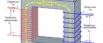
The idea of creating a temperature sensor is that it uses an electrically conductive element, which, under the influence of fluctuations in ambient temperature, changes its resistance. Such an element is a thermistor.
The operating principle of variable resistance is that when heated, the resistance decreases and the current flowing through it changes its characteristic. This process is reflected in the operation of the application circuit, which turns on or off the corresponding devices.
Assembly
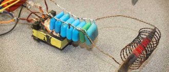
Having prepared the above materials and tools, we proceed to soldering a simple circuit.
- The positive terminal of the power supply is connected by a wire to the input contact (+) of the cooler;
- The three terminals of the field-effect transistor are soldered with wires like this: “source” with a cooler, “gate” with a thermistor, “drain” with a variable resistor.
- Wires connect the free contacts of the thermistor to the “+” of the power supply, and the variable resistor to the “−” of the same block.
Examination
Test the thermostat in this order:
- bring a burning match or lighter to the thermistor and the cooler should start working;
- when cooling, the fan should turn off;
- if the circuit does not work, you need to recheck the soldering and contacts.
TR - thermistor, K - cooler, R1 - variable resistor, PT - field-effect transistor, AB - 12 V battery.
Communities › Kulibin Club › Blog › Electrics: Temperature sensors, we make it ourselves.
Sometimes there is a need for temperature control of some process, be it a car or a national economy. There are many different thermal control schemes, but the sensors usually have an inconvenient design that does not allow for mounting in a controlled environment. Let's talk about sensors.
As a rule, semiconductor devices - thermistors - serve as sensors for measuring circuits:
The case may be different, but inside there will still be about the same droplet with leads.
The second common temperature sensor is the DS1820:
They are often sold as follows:
Inside is the same DS18B20 microcircuit with three pins, even without thermal paste.
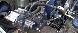
Now let's try to implement these radio components into a car, for example, for digital display of coolant temperature or control of electric fans.
We will need a donor sensor - any suitable thread and cost. In my case, this is the Volga-UAZ sensor TM 106-10
:
We take a drill as a lathe and carefully clamp the sensor into the chuck. Using a metal hacksaw, we cut off the rolling. When the sensor falls apart into its component parts, use a drill to even out the edge of the sensor with a file. We receive a blank housing for introducing our radio component there.
Then you can go in two ways: 1. Pour molten solder into the body, drill a channel in this solder and insert a thermistor there. You can fill the housing cavity with thermal paste and stick the thermistor into it, but tin’s thermal conductivity is several orders of magnitude better than thermal paste, so thermal paste must of course be used, but it’s better to apply a thin layer of it.
The disadvantage of this method is the high inertia of the resulting sensor.
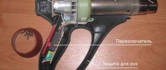
2. Do it the way I do it. Take a telescopic antenna from some old unnecessary device:
If you threw them away before, you did it in vain, because such antennas are a source of wonderful thin-walled brass tubes of different diameters:
We select the tube most suitable for the thermistor - it should be inserted as tightly as possible into the tube. We measure and again use the drill, cut off the piece of tube we need - it’s better to cut with a needle file. We take our blank body and drill its end according to the diameter of the tube. We tin the end of the body with tin, strip the tube down to brass and also tin it. We insert the tube into the case and solder them to each other, an 80W soldering iron is enough for your eyes. It should look something like this (the end is already sealed with a small piece of copper foil 1mm thick):
We check the resulting sensor housing for leaks. I do it not very technologically - using tongue suction
We advise you to study All types of voltage converters
If everything is in order with the tightness, we proceed to the next stage: installing the thermistor and connector.
Again, we try everything on and cut off the leads of the thermistor so that when installed in the housing, the thermistor is at the end of the tube, or better yet, rests against the end:
The thermistor is now ready for installation. We put a little thermal paste inside the tube, coat the thermistor itself with a little thermal paste and insert it into the tube. After the thermistor has entered the tube under the connector, we place a little pre-prepared poxypol or epoxy plasticine. We press the connector into the polyester and remove the excess. When the Poxypol has completely hardened, you get this nice sensor ready for installation:
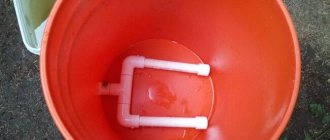
And this is how the sensor will stand at its workplace - the measuring part will be completely washed by the working environment:
Well, here’s a picture of a general check of the functionality of the electrical part:
Thermal sensor on germanium diodes
A feature of germanium semiconductor diodes is their high sensitivity to changes in air temperature. Therefore, these radio components can be used as temperature sensors when they are turned back on.
Their use is explained by the strong dependence of the reverse current on the ambient temperature. This feature of the diodes is used in a simple cooler speed controller circuit.
Germanium diodes connected in parallel (3–4 pieces) are connected in the opposite direction to the base circuit of the composite transistor. Their glass cases can be mounted directly on the cooler without any heat sinks. Resistor R1 protects the transistor from thermal breakdown, and R2 determines the response threshold of the regulator. If the fan does not turn on when the room temperature is exceeded, then the number of diodes must be increased. When the cooler begins to rotate the blades at high speed, the number of radio components is reduced.
Types of temperature controller for heating boiler
In the basic version, boiler units are equipped with a simple thermostat that monitors the degree of heating of the coolant in the system. The homeowner sets the required number of degrees manually, then a simple thermocouple based on a bimetallic plate begins to work. It activates heating of the coolant, including a gas burner or heating element in an electric boiler.
More expensive models are equipped with remote thermostats. They control the temperature through several channels:
- control of the degree of heating of the coolant in the heating system;
- monitoring air temperature in a remote room using a remote sensor;
- turning on the heating using a weather-sensitive sensor installed outside;
- control of a boiler installation using an external room thermostat.
Weather-dependent control systems are used less frequently than others. This is due to their high price, complexity of setup and installation. However, they provide the most efficient control of the boiler installation: the system quickly responds to changes in the weather outside, without waiting for the temperature in the room to drop or rise.
The temperature controller, installed at a distance from the boiler, becomes an external control module. It consists of a compact thermometer, a logic circuit and switching equipment. Its main task is to monitor the set temperature based on thermoelement readings. If the room gets cold, it turns on the heating remotely. When the temperature reaches the set value, the boiler will turn off.
Boiler peripherals with built-in controls can also perform other tasks. They can:
- Adjust the temperature in the hot water supply circuit.
- Set different operating modes of the boiler installation depending on the time of day or day of the week.
- Control heating according to a preset program.
- Operate external equipment. The thermostat can control indirect heating boilers, solar collectors and underfloor heating systems.
For your information!
The remote design of the thermostat allows you to control boiler equipment located remotely. Thanks to this, the building will maintain the set temperature, even if the heater is located in the basement or in a separate building.
The layout and functionality of the equipment varies widely. The simplest devices have a single knob for mechanical adjustment. Modern complex mechanisms are built on an electronic base. They can regulate the temperature through several channels and are equipped with electronic displays that display various indicators. They cost more, but they allow you to increase the efficiency of heating, saving your budget.
Using a thermal sensor on Arduino
To assemble a temperature meter based on an Arduino microcontroller, you need to prepare the following:
- Arduino UNO;
- connectors;
- circuit board;
- digital module DS18B20 (range from −56 to +1250 C).
The DS18B20 digital temperature sensor is a device that not only signals when a specified temperature threshold has been exceeded, but can also store measurement values. The sensor chip has three output contacts - “+”, “−” and a signal wire. The waterproof temperature sensor is used to measure the heating of water or liquids.
A temperature sensor can always be purchased, like an Arduino board, in online stores. The digital module is connected to Arduino via GND channels, and the Vdd output is connected to 5V, Data to any Pin. For a clearer understanding, the connection diagram of the DS18B20 digital sensor to Arduino is shown in the photo below.
DIY thermostat: diagram
About the design of the thermostat, we can say that it is not particularly complicated, it is for this reason that most radio amateurs begin their training with this device, and also hone their skills and craftsmanship on it. You can find a very large number of device circuits, but the most common is a circuit using a so-called comparator.
This element has several inputs and outputs:
- One input responds by supplying a reference voltage that corresponds to the required temperature;
- The second receives voltage from the temperature sensor.
The comparator itself receives all incoming readings and compares them. If it generates a signal at the output, it will turn on the relay, which will supply current to the heating or refrigerating unit.