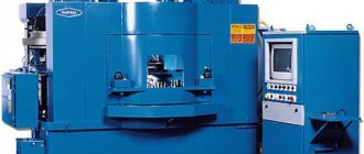
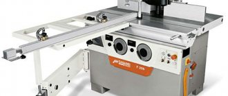
Boring machines: purpose and areas of use
Such equipment can be used to perform such operations as:
- thread cutting, internal and external;
- drilling blind and through holes;
- countersinking;
- trimming the ends of workpieces;
- face and cylindrical milling, etc.
Most often, this equipment is used for finishing or semi-finishing. However, it happens that with its use they also produce finishing. The part body is rarely processed on such machines, but sometimes this operation is still performed. Repair of a boring machine is carried out using approximately the same technology as a turning machine. The same applies to operating features. The design of these two types of machines is similar. Like many other special types of equipment designed for processing metal and wood workpieces, a boring machine was once designed on the basis of a lathe.
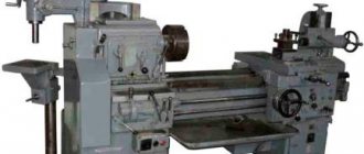
2L614 – about equipment characteristics
This machine also represents a group with universal products. It is used when processing body parts weighing no more than 1000 kilograms. Other features are also characteristic:
- Equipped with a built-in rotary table. Standard movements - using longitudinal, transverse directions. They are also followed in product 2a622f4.
- It is worth noting the presence of a front pillar, which is motionless.
- Among the main units is an alternating current electric motor, which is responsible for organizing the rotational movement, which is carried out with the participation of the spindle and faceplate.
- It is easier to control the process when using a gear selection mechanism with a handle. As in option 2a622f4.
The 2l614 modification machine is always supplemented not only with a built-in type of faceplate, but also with a radially moving caliper. The list of operations performed is larger thanks to the radial caliper.
When machining, you can use the so-called retractable spindle. Then milling work makes it possible not to use a radial type caliper.
The machines will benefit enterprises in the field of mechanics and tool production. In terms of accuracy, there is correspondence to the category designated H. Products 2a622F4 are designed differently.
Video: CNC horizontal boring machine.
Types of boring machines by design
Enterprises can use three main types of such equipment:
- horizontal boring machines;
- coordinate boring;
- diamond boring.
The first two types of machines are most widespread. The spindle is responsible for moving the tool in all types of such equipment. When performing workpiece processing operations, tools such as drills, reamers, and countersinks can be used. Sometimes a milling cutter is also used.
Model range of jig boring machines
Many manufacturers produce such equipment today. But most often, enterprises use jig boring machines:
- 2E450. This single-column model has table dimensions of 630 x 1120 mm and is equipped with an optical measuring system complemented by an on-screen readout. This boring machine also has an automatic slide stop function. Another addition to this model that increases ease of use is the device for pre-setting coordinates.
- 2D450. This model also has table dimensions of 630 x 1120. The optical device included in its design can measure both whole and fractional parts of coordinates.
Of course, other coordinate boring machines can also be used in enterprises. Models 2A450, 2L450AF11-01, for example, are also in great demand today.
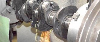
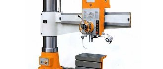
Horizontal boring models
The main design feature of this type of machine is that the spindle is located in a horizontal position and can be extended. This allows you to make holes even in the most difficult to reach places, including large parts (booms, frames, metal structures).
The main movement of horizontal boring models is rotational-translational. It is performed by a spindle. Not only the tool itself moves in such machines, but also the workpiece. If necessary, you can switch feeds and speeds during operation. In some cases, feeding is carried out using a special substrate.
Depending on the configuration, in addition to the main movements, such machines may have auxiliary ones:
- spindle head along the vertical axis;
- table at given coordinates.
Also, the design of some models allows for the possibility of moving the rest and rear pillar. Below is a diagram of this type of boring machine. Horizontal models can be used for processing parts made of cast iron or cast steel.
Kinematic diagram of finishing and boring machine 2E78P
Kinematic diagram of finishing and boring machine 2e78p
The kinematic chains of the main movement, rapid strokes and feed movements, the sequence of transmission of rotation from electric motors to the executive bodies are clear from the diagram.
The spindle head feed mechanism safety clutch is adjusted to transmit a torque of 25 Nm, in accordance with the permissible feed force.
The safety clutch of the high-speed table movement mechanism is adjusted to transmit a torque of 20 Nm in accordance with the permissible force during high-speed table movement.
If the permissible forces in the spindle head feed mechanism are exceeded (mainly in the case of incorrectly selected cutting modes) and in the table high-speed mechanism, the safety clutches slip with a characteristic crack.
Work table of machine 2E78P
The movement of the workpiece in two mutually perpendicular directions on the 2E78P model machines is carried out using a table consisting of two parts: the lower - a slide moving in the transverse direction along the guide bases, and the upper - the table itself, moving in the longitudinal direction along the guides of the slide
Two reading microscopes with a vernier accuracy of 0.01 mm can be installed on the front and side walls of the machine slide: one for measuring coordinates when moving the table in the longitudinal direction, the second in the transverse direction.
A ruler for accurately measuring the longitudinal movements of the table is located on the front wall of the table, a ruler for accurately measuring the transverse movements of the table is on the left wall of the base.
Adjustment movements of the table, longitudinal and transverse, as well as installation according to coordinates are carried out manually using flywheels.
In the desired position, the table is fixed with two handles using eccentric clamps.
The installation movement of the table in the longitudinal direction can be carried out mechanically from a high-speed electric motor. To do this, the high speed selector handle is rotated to a vertical position. In this case, rotation is transmitted to the lead screw through a screw pair. The working feed of the table is switched on by switching the handle. In this case, rotation is transmitted to the lead screw from the gearbox in the table through a worm gear.
Changing the direction of fast moves of the table is carried out by alternately pressing the table drive buttons “Right” or “Left”, as a result of which the high speed electric motor is reversed.
To prevent breakdowns of the table drive mechanism due to overloads, the corresponding table shaft is connected using a ball safety clutch designed to transmit maximum torque.
Column of machine 2E78P
The column is attached to the base. Along its guides - prismatic and flat - the spindle head moves in the vertical direction.
In the upper part of the column, rollers are mounted on the bracket, along which the chain of the counterweight moves inside the column.
The counterweight, which balances the weight of the headstock with the spindle, consists of a solid cast iron.
At the front wall of the column, between the guides, there is a spindle head lead screw and a splined spindle drive shaft, mounted in the upper part of the column in attached brackets.
At the bottom of the column there is a gearbox and feed box installed on the base. The box control, consisting of a feed shift knob and three speed shift knobs, is located on a cover located on the right wall of the column.
Two limit switches are installed above the cover to limit the up and down movement of the spindle head. There is an electrical cabinet in a niche in the rear wall of the column. Through the windows of the column, covered with a lid in the rear wall, access is provided to the screws that secure the counterweight of the spindle head to the column during transportation of the machine.
To transport the column, two holes with a diameter of 55 mm are used.
Spindle head of machine 2E78P
The spindle head moves vertically along the column guides. It contains mechanisms for spindle drive, spindle head drive and manual movements.
Replacement spindles are installed with a seating belt into the spindle head body and secured with six nuts.
The spindle drive is carried out through a V-belt drive. The drive pulley of this transmission is mounted on a splined sleeve rotating in bearings, which, when the spindle head moves, slides along the splined roller of the column emerging from the gearbox and feeds.
The driven pulley is mounted on a shaft that has a cam coupling at the splined end, through which rotation is imparted to the spindle. The belts are tensioned using a tension roller. Cam clutch - controlled; it is turned on manually using a handle located on the left wall of the spindle head, through a roller with an eccentric finger.
Disconnecting the spindle with a clutch from the kinematic chain of its drive makes it easier to rotate the spindle by hand when installing and centering the workpiece along the boring axis.
The manual movement mechanism consists of a gear nut rotating in bearings and meshed with a worm. The worm sits on the same shaft as the flywheel. When the flywheel rotates, the worm rotates the gear nut, moving the spindle head.
In mechanical feed, when the lead screw rotates, the gear nut is kept from turning by a self-braking worm gear. This design of the manual movement mechanism allows you to intervene in the mechanical feed, thereby reducing the time for approaching the cutter for cutting.
The spindle head is equipped with a device for manual radial movement of the cutter, which allows boring holes of various diameters, trimming the end of the bored hole and risk-free removal of the cutter from the machined hole. The handwheel for manual movement of this device with a dial and indicator is located on the front wall of the spindle head.
The spindle headstock is pressed against the guides by clamping bars. Height-adjustable cams are attached to one of the bars to disable the movements of the spindle head.
On the same side of the spindle head there is a ruler for measuring the length of the surface to be machined. The handwheel for manual movements is equipped with a dial for measuring the cutting depth when trimming the ends.
The ribs inside the spindle head housing form a bath used as an oil reservoir for the lubricator, from which the guides and bearings of the rotating shafts are lubricated.
Machine speed and feed box 2E78P
The speed and feed box is installed on the base inside the column and serves to transmit rotation from the main drive electric motor to the spindle drive shaft and the spindle head lead screw, as well as to transmit rotation from the high-speed motor to the spindle head lead screw.
It provides the spindle with twelve spindle rotation speeds and four working feed rates and accelerated headstock movement.
Inside it are located:
- worm-gear;
- bevel with a spiral tooth and cylindrical spur gears, providing the necessary gear ratios;
- mechanisms for switching speeds and feeds;
- overrunning double-sided clutch.
A glass with a high-speed drive pulley shaft is attached to the bottom of the box.
The gearbox and feeds are controlled by four handles:
- three are designed to switch spindle rotation speeds;
- the fourth is for switching feed rates.
Three gear shift handles are located on the same axis.
The gear shift mechanism consists of three gears mounted on three coupling halves located concentrically on one axis. The gears are connected to three forks—racks that switch the gear blocks. The grooves of the coupling halves, on which the gears are fixed, include the teeth of the coupling halves, on which the handles are fixed (Fig. 13).
The feed switching mechanism consists of a crank with a stone that moves the triple fork.
In positions corresponding to the inclusion of certain positions of speeds and feeds, the forks are held by ball retainers.
The overrunning double-sided clutch allows for accelerated movement, working and manual feed of the spindle head. During working feed, the outer race of the coupling, rigidly connected to the worm wheel, receives rotation from the worm and drives the hub connected to the lead screw through the rollers; with manual feed, the outer race of the coupling does not rotate, since it is held by a self-braking worm pair. During accelerated movement, the middle race of the clutch rotates the inner race and the lead screw through the rollers.
The clutch rollers are pressed by springs. Thanks to the overrunning clutch, it is possible to enable the accelerated movement of the spindle head without turning off its working feed.
To prevent damage to the gearbox and feeds due to overload, the lead screw is connected using a ball safety clutch designed to transmit maximum torque.
Types by layout
A boring machine is typically used to machine complex parts with many holes, grooves, and shoulders. According to the layout, this equipment is classified into:
- Models with spindle diameter up to 125 mm. Using such equipment, small workpieces are usually processed. The table of such models can move along two axes. The boring head is capable of moving along the column in a vertical direction.
- Equipment with a spindle diameter of 100-200 mm. This boring machine is designed to work with medium-sized and large workpieces. With such machines, the table moves only in one direction.
- Models with spindle 125-320 mm. This equipment is used for processing very large parts. These machines have a stationary table.
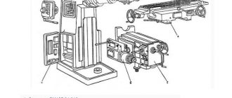
Location of the components of the finishing and boring machine 2E78P
Location of the main components of the boring machine 2e78p
Specification of components of finishing and boring machine 2E78P
- Spindle 0.48 mm - 2E78P.71.000
- Spindle 0.78 mm - 2E78P.72.000
- Spindle 0.120 mm - 2E78P.73.000
- Universal spindle - 2E78P.74.000
- Special spindle - 2E78P.75.000
- Control panel - 2E78P.83.000
- Panel electrical equipment - 2E78P.81.000
- Column - 2E78P.30.000
- Table - 2E78P.40.000
- Base 2E78P.10.000
- Reading device - 2E78P.40.020
- Gearbox and feed - 2E78P.50.000
- Spindle head - 2E78P.23.000
- Electrical equipment stage - 2E78P.80.000
- Remote control panel - 2E78P.82.000
- Control panel - 2E78PN.83.000
- Panel electrical equipment - 2E78PN.81.000
- Base - 2E78PN.10.000
- Electrical equipment of the machine - 2E78PN.80.000
- Remote control panel - 2E78PN.82.000
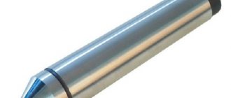
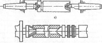
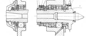
Replacement spindles for machine 2E78P
The replacement spindles consist of three spindles with cutting head diameters of 48, 78 and 120 mm.
The spindle is installed on the spindle head taking into account the diameter of the hole to be bored. Spindle with a diameter of 48 mm - for boring holes with diameters from 50 to 82 mm; with a diameter of 78 mm - from 82 to 125 mm; with a diameter of 120 mm - from 125 to 200 mm.
The spindles are assembled on precision angular contact ball bearings. The penetration of dust into the bearings is prevented by labyrinth seals.
There is a slider in the spindle head, which makes it possible to carry out radial feed of the cutter. A rod passes inside the spindle, which serves to move the slide.
The movement of the cutter in spindles with diameters of 48 mm, 120 mm, 78 mm and special is carried out along a dial in the cutting head.
The cutters are secured using a clamping screw. The threaded hole located at the end of the cutting head is necessary for installing the center finder.
When installing a scoring cutter on the cutting head, it is possible to trim the end of the workpiece.
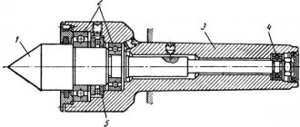
Universal spindle
The universal spindle is installed on the machine for boring holes with diameters from 27 to 200 mm of small depths using boring bars or a tool holder with precise feed, as well as for drilling or reaming holes in individual parts and for milling,
The spindle is assembled on precision angular contact double ball bearings.
The receiving cone of the spindle is made in accordance with GOST 15945-70, and the end of the spindle is made in accordance with GOST 24644-81 and is designed for the use of an auxiliary tool, or a normal tool in combination with adapter bushings.
The nut at the end of the spindle is used to tighten and remove the tool. To remove the tool, the nut should not be completely unscrewed with the 2E78P.74.010 wrench.
The end of the receiving cone is equipped with keys into which, when secured, the tool fits into its grooves. This device for fastening the tool ensures that it does not rotate in the spindle cone and protects the spindle from damage.
Special spindle
A special spindle is used for boring V-shaped engines with diameters from 82 to 125 mm.
The spindle is made structurally similar to a replaceable spindle with a diameter of 78 mm with radial movement of the cutter.
Features of coordinate boring models
Machines of this variety are used for drilling holes according to precisely specified parameters. This operation can be performed on different workpieces (conductor plates, body parts, etc.). High processing accuracy is ensured by the presence of special devices in the design of coordinate boring models: mechanical, optical and electronic. In addition, such models are equipped with rotary tables. This allows holes to be made in polar coordinate systems without having to move the part. Enterprises can use two-column or single-column jig boring machines. The dimensions of models of this type, unlike horizontal ones, are not too large.
Features of working on a coordinate boring machine
When using this type of equipment, the workpiece being processed is first secured on the work table. Next, the required cutting tool is installed in the spindle. The work is then done in the following order:
- depending on the height of the workpiece, adjust the traverse and boring head;
- set the spindle to the specified coordinates.
The last operation on equipment such as a jig boring machine, depending on its type, can be performed in different ways. On a single column model, the spindle is installed properly by moving the work table in two perpendicular directions. On two-rack equipment:
- the table is moved longitudinally;
- the boring head is moved in the transverse direction along the traverse.
Diamond boring machines
Models in this group are designed mainly for fine boring of cylindrical surfaces. If additional components are available, they can also be used to process shaped and conical rotating surfaces, grooves and ends. When using such machines, it is possible to simultaneously drill several holes with parallel axes. Diamond boring machines can be:
- vertical;
- inclined;
- combined;
- horizontal with a movable table.
Technical characteristics of finishing and boring machine 2E78P, 2E78PN
| Parameter name | 2E78P | 2E78PN |
| Main parameters of the machine according to GOST 9520-73 | ||
| Machine accuracy class according to GOST 8-82 | P | P |
| The diameter of the bored hole is largest/smallest, mm | 200/ 28 | 200/ 28 |
| The largest drilling diameter in steel is 45, mm | 15 | 15 |
| Largest dimensions of the workpiece, mm | 750 x 500 x 450 | 750 x 500 x 450 |
| Maximum mass of the processed product, kg | 200 | 200 |
| Minimum distance from the end of the spindle to the table, mm | 25 | 25 |
| Accuracy of longitudinal/transverse center-to-center coordinates, mm | 0,03/ 0,025 | 0,03/ 0,025 |
| Distance from the spindle axis to the rack (spindle overhang), mm | 320 | 320 |
| Headstock | ||
| Maximum vertical movement of the spindle head, mm | 500 | 500 |
| Amount of movement per one revolution of the flywheel, mm | 0,75 | 0,75 |
| Spindle speed, rpm | 26..1200 | 26..1200 |
| Number of spindle speeds | 12 | 12 |
| Limits of working feeds per spindle revolution, mm | 0,025..0,200 | 0,025..0,200 |
| Number of innings | 4 | 4 |
| High speed, mm/min | 2000 | 2000 |
| Overload protection of the feed mechanism (clutch) | available | available |
| Switching stops | available | available |
| Automatic return to the starting position after the end of boring | available | available |
| Desktop | ||
| Working surface of the table, mm | 1000 x 500 | 1250 x 500 |
| Maximum table movement, mm | 800/ 200 | 800/ 200 |
| Table working speed in longitudinal/transverse direction, mm/min | 100/ no | 100/ no |
| Movement of the machine table per one revolution of the flywheel in the longitudinal/transverse direction, mm | 4,2/ 2,9 | 4,2/ 2,9 |
| The amount of accelerated table movement in the longitudinal/transverse direction, mm/min | 2000/ no | 2000/ no |
| Method of counting coordinates when moving the table | microscope | — |
| Mechanical high speed release stops | available | available |
| Securing the table of the machine model 2E78P from movement | manual | manual |
| Drive unit | ||
| Number of electric motors on the machine | 3 | 2 |
| Main motion drive electric motor, kW | 2,2 | 2,2 |
| Electric motor for spindle head rapid speed drive, kW | 0,75 | 0,75 |
| Table drive electric motor, kW | 0,75 | No |
| Machine dimensions | ||
| Dimensions of the machine, including table travel (length x width x height), mm | 1750 x 1560 x 2125 | 1250 x 1260 x 2125 |
| Machine weight, kg | 2680 | 2100 |
- Vertical finishing and boring machines 2E78P, 2E78PN. Operating manual 2E78P.00.000 RE, 1979
- Bernstein-Kogan V.S. Electrical equipment of jig boring and thread grinding machines, 1969
- Glukhov N.M. Working on jig boring machines, 1953
- Grigoriev S.P., Grigoriev V.S. Practice of coordinate boring and milling work, 1980
- Ipatov S.S. Jig boring machines in precision instrumentation, 1954
- Kashepava M.Ya. Modern jig boring machines, 1961
- Kudryashov A.A. Tool production machines, 1968
- Smirnov V.K. Turner-borer. Textbook for technical schools, 1982
- Tepinkichiev V.K. Metal cutting machines, 1973
- Zazersky E.I., Gutner N.G. Turner-borer, 1960
- Ponomarev V.F. Handbook of a lathe-borer, 1969
- Smirnov V.K. Turner-borer. Textbook for technical schools, 1982
- Bogdanov A.V. Boring business, 1960
Bibliography:
Related Links. Additional Information
- Classification and main characteristics of drilling-milling-boring group of machines
- Selecting the right metalworking machine
- Machine repair technology
- Methodology for checking and testing drilling machines for accuracy and rigidity
- Directory of drilling machines
- Manufacturers of drilling machines in Russia
- Manufacturers of metal-cutting machines
Home About the company News Articles Price list Contacts Reference information Interesting video KPO woodworking machines Manufacturers
Price
Boring machines in many cases are classified as special-purpose equipment. Therefore, most of them are very expensive. There are models whose price can be millions of rubles. Some machines are cheaper - several hundred thousand. The price of equipment of this type, like any other, depends primarily on its technical characteristics. Today, there are also used machines of this type on the market. They are, of course, cheaper than new ones.
Machine 2733P – where to buy, payment, delivery, warranty
The price for the vertical finishing and boring machine 2733P is indicated on our website including VAT for the standard delivery set.
It’s easy to buy a 2733P machine - just call the numbers below in your city.
The sale of a high-precision diamond boring machine model 2733P is made with 100% advance payment if the equipment is in stock and 50% advance payment when the machine is put into production and payment of the remaining 50% after notification of its readiness for shipment. A different percentage and a different payment procedure may be agreed upon with a specialist from the sales department of our company. Delivery of equipment is carried out by road and rail transport of carrier companies LLC "Business Lines", LLC "PEK", "Baikal-Service", LLC "Zheldorekspeditsiya" and other third-party carriers through transport and logistics companies, as well as by the transport of the Buyer or our company. The costs of transporting the goods are paid by the Buyer, unless otherwise specified in the Delivery Agreement. The warranty for the new vertical finishing and boring machine 2733P is 12 months. The manufacturer reserves the right to change the standard configuration and place of production of the equipment without notice!
Read also: Do-it-yourself spot welding for cars
We draw your attention to the fact that the prices indicated on our website are not a public offer, and check the cost of the equipment with the machine sales managers!
If you need to buy a Vertical finishing and boring machine 2733P, call:
in Moscow in St. Petersburg in Minsk +375 (17) 246-40-09 in Ekaterinburg in Novosibirsk in Chelyabinsk in Tyumen +7 (3452) 514-886
in Nizhny Novgorod in Samara in Perm in Rostov-on-Don in Voronezh in Krasnoyarsk
in Nur-Sultan;
in Abakan, Almetyevsk, Arkhangelsk, Astrakhan, Barnaul, Belgorod, Blagoveshchensk, Bryansk, Vladivostok, Vladimir, Volgograd, Vologda, Ivanovo, Izhevsk, Irkutsk, Yoshkar-Ola, Kazan, Kaluga, Kemerovo, Kirov, Krasnodar, Krasnoyarsk, Kurgan, Kursk , Kyzyl, Lipetsk, Magadan, Magnitogorsk, Maikop, Murmansk, Naberezhnye Chelny, Nizhnekamsk, Veliky Novgorod, Novokuznetsk, Novorossiysk, Novy Urengoy, Norilsk, Omsk, Orel, Orenburg, Penza, Perm, Petrozavodsk, Pskov, Ryazan, Saransk, Saratov, Sevastopol, Simferopol, Smolensk, Syktyvkar, Tambov, Tver, Tomsk, Tula, Ulan-Ude, Ulyanovsk, Ufa, Khabarovsk, Cheboksary, Chita, Elista, Yakutsk, Yaroslavl and other cities
Toll-free number throughout Russia.
In the CIS countries - Belarus, Kazakhstan, Turkmenistan, Uzbekistan, Ukraine, Tajikistan, Moldova, Azerbaijan, Kyrgyzstan, Armenia in the cities of Nur-Sultan, Bishkek, Baku, Yerevan, Minsk, Ashgabat, Chisinau, Dushanbe, Tashkent, Kiev and others for purchase equipment such as Vertical finishing and boring machine 2733P, call any convenient number listed on our website, or leave your contacts under the ORDER A CALL button at the top of the site - we will call you back.
Boring machines: domestic and foreign models
Boring machines are represented quite widely on the domestic market. There are many brands of this equipment. Examples include:
- Machines of the WH, WHN, WRD series produced by TOS Varnsdorf.
- Mobile Climax models made in the USA.
Soviet models of this group are still very popular on the market. For example, if you wish, you can purchase horizontal boring machines 2A614, 2A622, 2A635 or coordinate boring machines 2421, 2E440, 2E450, etc.
Work – what principle is it based on?
Feed movements are the main operating feature of these devices. Several important elements and principles need to be described here:
- Fastening of cutting tools occurs with the participation of a faceplate support or spindle. This is where the rotation begins. The principle continues in the 2620a models.
- Placement on the surface of a movable table, using a special device.
- When working, the table moves, lengthwise or crosswise. 2620V models have the same capabilities.
The front post is involved in the movement of the spindle head, while maintaining the vertical direction. The support steady rest is combined with the stand at the rear. The movement of two parts occurs simultaneously.
When holes are bored or internal threads are cut, a translational movement is carried out by a boring spindle. When a part is processed using a 2620 horizontal boring machine, the faceplate with the caliper moves only in the radial direction.
CNC boring machines
Models of this variety have many advantages compared to conventional ones. Their work is controlled by a computer with a program embedded in it. This allows for high processing precision and maximum productivity. The program is written in special codes specified in the description of the machine. This modern equipment can be used for both roughing and finishing of parts.
Boring machines are equipment that is truly in demand and in many cases irreplaceable. Especially when you need pinpoint precision or maximum performance. If an enterprise has a need for equipment of this type, finding a suitable model on the modern domestic market will not be difficult.
Information about the manufacturer of finishing and boring machine 2E78P
Manufacturer of finishing and boring machine 2E78P - Maikop Machine Tool Plant named after. Frunze .
Maikop Machine Tool Plant named after. Frunze is one of the largest manufacturers of metal-cutting machines in the south of Russia. Created on the basis of the Gursky iron foundry founded in 1892.
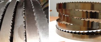
The plant specializes in the production of finishing and boring, honing machines with a wide range of capabilities for repair and service of internal combustion engines (automobile, tractor, ship), band saws, high-precision finishing machines and others.
Machine tools produced by the Maikop Machine Tool Plant named after. Frunze
- 2A78
- vertical finishing and boring machine 500 x 1000 - 2A78N
- vertical finishing and boring machine 500 x 1250 - 2E78P, 2E78PN
- finishing and boring machine 500 x 1000 - 3G833
- vertical semi-automatic honing machine - 3K833
- semi-automatic vertical honing machine - 8A531
- vertical band saw machine for cutting metal
Purpose of the equipment
Jig boring machines are designed to process holes with strict adherence to the center-to-center distances between them and orientation relative to the base surfaces. In this case, the counting occurs in a rectangular coordinate system without the use of additional means of guiding the tool. Such machines are used in both individual and mass production.
The main work on such machines includes:
Machine coordinate system
- drilling, boring holes (rough, finishing);
- turning cylindrical surfaces from the outside;
- processing the ends of holes, as well as their deployment, countersinking;
- milling of flat surfaces;
- thread formation;
- measuring parts.
In addition, the equipment allows you to drill holes in conductors and body elements, where the utmost accuracy of their relative position is important. Diamond boring machines are designed for boring cylinders, bushings, connecting rods and other engine parts.
Standard machine coordinate system
In addition to boring work, the machines can be used to perform markings, control dimensions, and check center-to-center distances. Using rotary tables (included with the equipment), holes are machined, the location of which is determined by the polar coordinate system, as well as inclined and mutually perpendicular holes.
Boring machines are equipped with optical-based reading devices. This makes it possible to count within whole and fractional parts of the coordinate size. The accuracy with regard to center-to-center distances reaches about four thousandths of a millimeter. More accurate devices are equipped with a digital distance display system and allow the operator to set coordinates with an accuracy of 0.001 mm.