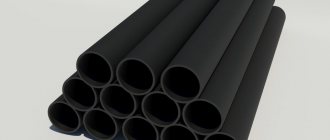
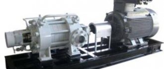
A worm gearbox is an equipment that converts the torque of an engine using a worm gear, operating by engaging the teeth of the shaft and the wheel. Worm - a threaded screw. As it rotates, the threads move along the axis, and the teeth of the wheel move in the same direction. The gearbox can have one or several PP - (mechanical) planetary gears - rotational motion gears. A motor with a built-in worm gear is called a gearmotor. Thanks to their design, they are practically silent, compact, the operating process is smooth, and are quite in demand in mechanical engineering https://tehprivod.ru/katalog/motor-reduktory/chervyachnye-motor-reduktory/chervyachnye-motor-reduktory-nmrv/
The axes of the worm or helical gear, wheel and worm intersect at right angles, forming a worm gear; the distance between these parts determines the size of the device itself. The worm gear is based on a gear-screw. Despite this, they are very different. In a worm gear, the teeth are replaced by threads, and the gear itself is replaced by a worm screw. Gears are divided into cylindrical and globoid (depending on the type of worm with the corresponding names).
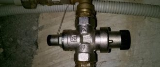
Gearbox with top worm.
A single-stage gearbox with an upper worm is used when, according to the equipment layout, it is advisable to place the worm shaft above the worm wheel shaft. The disadvantage of this scheme is increased heating of the worm due to the inability to ensure its abundant lubrication. In addition, bearings cannot be lubricated by oil poured into the housing. With a circulation lubrication system, gearboxes with a lower and upper worm are equivalent.
Worm shaft support option.
What are the advantages of worm gear reducers?
Modern worm gearboxes, including models of the Ch type, are characterized by a number of advantages. Although these converters are also not without their shortcomings. But first things first.
Among the advantages of worm gearboxes, it is worth highlighting:
- compact dimensions – the process of installing the converter is simplified, the assembled equipment takes up less space;
- high level of gear ratios when using only one stage;
- Quiet operation thanks to high level of grip;
- smooth running and braking.
As for the disadvantages, the most significant of them is the rather low level of efficiency. The resulting energy loss causes the device to become very hot during operation. Due to rapid wear of working parts due to friction, the service life of the converter is reduced. On average it is about 10,000 hours.
Worm gearbox Ch-63.
Worm gearbox Ch-63 for general purpose, manufactured with gear ratios from 8 to 63. The gearbox has two supporting surfaces, which allows it to be used in any position in space. One supporting surface can be used to install an electric motor connected to the worm shaft by a V-belt drive. The lower location of the worm is preferable. The ribbed surface of the covers provides good heat dissipation, so it is possible to use the gearbox without using a fan.
Technical requirements.
- The permissible torque on a low-speed shaft during long-term operation with a quiet constant load and a worm rotation speed of 1500 min-1 T = 125 N⋅m.
- Short-term torque Tmax = 315 N⋅m.
- Nominal gear ratios: 8; 10;12.5; 16; 20; 25; 31.5; 40; 50;63. Gear ratio tolerance ± 4%.
- The axial clearance of the bearings on the worm is 0.02...0.05 mm by adjusting the gasket.
- The axial clearance of the worm wheel is 0.02…0.05 mm.
- The displacement of the middle plane of the worm wheel relative to the worm axis is no more than ± 0.034 mm.
- The technical requirements specified in paragraphs 5 and 6 must be ensured by fitting the gaskets.
- The smallest free rotation of the worm with a stationary wheel is 6°.
- Whatever the position of the gearbox in space, the vent plug should be located in the upper part.
- . When final assembling the gasket and roof, apply TU-D1-1211-79 paste.
Design features of a worm gearbox. Device and principle of operation.
Structurally, a worm gearbox consists of a durable metal housing, inside of which a worm gear is located. This mechanism consists of a so-called worm - a threaded screw, and a wheel equipped with arched oblique teeth that tightly fit around the circumference of the screw turns. As the screw moves, the threads cut along its axis move and drive the worm wheel. The axes of the wheel and worm are located at an angle of 90 degrees. The distance between these axes is an indicator characterizing the dimensions of the unit and is used in the technical description of the device. The center distance is indicated in mm. For example, NMRV-030, 060, 150.
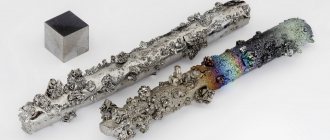
The worm gear housing is made of cast iron, which ensures high strength of the unit and wear resistance during operation. For ease of maintenance, the housing is of a composite structure, which makes it easy to disassemble for servicing internal components.
The screw is designed for high operating loads, so its material is alloy steel. The gear is made of a non-ferrous metal alloy, which is designed to reduce the coefficient of friction and eliminate overheating in the area of coupling of the lubs and the screw. The worm is the main link of the entire mechanism, and the gear receives torque from the gear, rotating the shaft at the output of the unit. The shaft is located at a right angle relative to the screw.
To prevent the worm gear from overheating due to the friction of moving components inside the unit, oil lubrication is used. To ensure tightness and stable fixation of all parts of the device, sealing elements are used, which also help to avoid oil loss during operation of the unit.
A worm-type gearbox, depending on the number of threaded channels and possible stages, can be multi-stage or single-stage. Single-stage devices are most often used due to the simplicity of the device, which guarantees stable operation under uniform loads.
Single stage drives
The single-stage mechanism differs from other models in its small, compact dimensions, and also ensures maximum force transmission during operation. In a single-stage unit, the low-speed shaft can be located on the right, left, or on both sides of the housing.
Depending on the assigned tasks and installation features, the appropriate type of device layout is selected. The worm gearbox, equipped with a single-stage drive, features smooth operation and self-braking function.
Multi-stage worm gear drives
When it is necessary to ensure operation with a high gear ratio, a worm gearbox with two or more stages is used. The location of the screw in multi-stage units is horizontal or vertical next to, under or above the wheel.
The multi-stage mechanism is selected taking into account the assigned tasks and the operating features of the unit. When the gear is placed on the side, the level of lubricant located in the vertical shaft bearing is reduced.
Worm gearbox RCHU-80.
A special feature of the RChU-80 worm gearbox is its housing design. The case is made without a connector, with a cover, which simplifies the design of the case. To attach the housing to the plate or to the body of another machine, removable corners are provided, which can be installed as shown in the drawing, or fixed to the gearbox housing in its upper part, where corresponding holes are also provided.
Assembly diagrams.
B - end of the high-speed shaft.
T - end of the low-speed shaft.
Technical data.
*The given power values P correspond to continuous operating mode nB=1000 min-1.
- The material of the worm wheel rim is BrAZH9-4 bronze.
- The worm material is 40X steel.
- Heat treatment - hardening 45...50 HRCe.
Low-speed shaft option.
Gearbox repair
Simple worm gear repairs can be done on your own. If the motor and drive are combined in one housing, then the mechanism should be carefully disassembled.
The part of the common crankcase in which the drive is located must also be disassembled. If the worm drive design is made for a high-speed motor, then before proceeding with disassembling the gearbox, it is necessary to drain the transmission oil from the housing.
This type of gearbox uses high-quality bearings, so most often the need for repair occurs if the gear and worm are worn beyond the limit values. The working pair must always be simultaneously replaced with a complete repair kit, which, before entering the distribution network, must be correctly selected and tested on a special stand.
If the wear of the worm pair is insignificant, then the gap can be eliminated using special spacer washers on the driven shaft.
The design of the worm gear also allows for adjustment of the engagement of the gear with the worm without disassembling the housing. For this purpose, a bolt is used that is built into the housing. If you have a drawing of the device, you can easily determine where the gear is adjusted. If there is no drawing, then an indirect sign of the adjusting bolt will be the presence of a lock nut on it, which is used to fix the adjusted gap between the worm and the gear. It is extremely rare that gearbox bearings require replacement. Typically, the drive is equipped with high-quality ball bearings that do not require replacement or repair throughout the entire service life of the part. Bearings can only be damaged if the drive has been used for a long time without lubrication or with the use of low-quality lubricants.
Worm gearbox Ch-120.
The Ch-120 worm gearbox is available in five versions with a maximum gear ratio of 39. The ribbed surface of the housing base provides good heat dissipation and the ability to not use a fan.
Assembly diagrams.
B - end of the high-speed shaft.
T - end of the low-speed shaft.
Technical data.
Technical requirements.
- *Dimensions for reference.
- When adjusting bearings by selecting shims, the axial clearance must be maintained within the following limits: for a worm 0.15…0.2 mm; for a worm wheel 0.12…0.18 mm.
Advantages
- The first and main advantage in technical terms is that the worm gearbox is small in size and is considered small in size relative to the helical spur gearbox.
- The second important advantage is that such a gearbox is capable of working with a ratio of 1 to 110; in special cases, greater productivity is achieved with a small number of internal elements. No other type of energy transmission has been able to achieve such a coefficient. For example, to achieve such a coefficient in a helical helical gearbox housing, a three-stage mechanism will be required. However, such indicators are produced by a single-stage worm gearbox.
- The third absolute advantage is the simplicity of the design and low cost. Due to the fact that the worm type shaft has special teeth, it operates virtually silently with standardized lubrication and proper care.
- There is another advantage of the worm gear - the standardization of production.
- Also, during such a transmission there are no unnecessary shocks, which increases the smoothness and service life.
- Another positive point is irreversibility (self-inhibition). During this phenomenon, when the worm shaft stops, the shaft that was rotating thanks to the worm shaft also stops without being able to rotate.
Gearbox with a vertical worm wheel shaft.
A gearbox with a vertical shaft of a worm wheel has limited use; it is used in rotary mechanisms of cranes and other similar devices.
Related Pages
- Kinematic diagrams of gearboxes
- Gearbox with vertical shafts
- Gearbox with two high-speed shafts.
- Two-stage gearbox
- Two-stage coaxial gearbox
- Design options for shaft supports of a cylindrical two-stage coaxial gearbox
- Gearbox with torsion shafts
- Two-stage, three-flow coaxial gearbox
- Coaxial cylindrical gearbox with internal gearing of low-speed stage
- Geared motor MTs2S-125
- Cylindrical gearbox Ts2-160
- Two-stage cylindrical gearbox 1Ts2U.
- Gearbox Ts2-200.
- Special gearbox
- Gearbox Ts3KF-100
- Reducer RTC-500.
- Three-stage gearbox
- Reducer RCT-1015.
- Bevel gearbox K-125.
- Bevel gearbox
- Bevel-helical gearbox
- Helical worm gear motor.
- Helical-worm gearbox.
- Two-stage worm gearbox.
Types of worm gearboxes
Worm gearboxes can vary significantly depending on the application of the mechanism.
The main differences that can be used in the design:
- Different number of visits;
- Part material;
- Thread direction;
- Thread profile;
- Types of screw used.
These differences may be present in various combinations. The engineer decides what types of worm gearboxes to use at the design and development stage of devices and mechanisms that use these types of torque transmission.