Lever arm.
A lever is a rigid body that can rotate around a fixed axis. In Fig. 1) shows a lever with an axis of rotation. Forces and are applied to the ends of the lever (points and ). The shoulders of these forces are equal to and respectively.
The equilibrium condition of the lever is given by the rule of moments: , whence
.
| Rice. 1. Lever |
From this relationship it follows that the lever gives a gain in strength or distance (depending on the purpose for which it is used) as many times as the larger arm is longer than the smaller one.
For example, to lift a load weighing 700 N with a force of 100 N, you need to take a lever with a shoulder ratio of 7: 1 and place the load on the short arm. We will gain 7 times in strength, but will lose the same amount of times in distance: the end of the long arm will describe a 7 times greater arc than the end of the short arm (that is, the load).
Examples of levers that provide a gain in strength are a shovel, scissors, and pliers. The rower's oar is the lever that gives the distance gain. And ordinary lever scales are an equal-armed lever that does not provide any gain in either distance or strength (otherwise they can be used to weigh customers).
What is leverage and when did it begin to be used?
Probably everyone has been familiar with this simple mechanism since childhood. In physics, a lever is a combination of a beam (rod, board) and one support. It serves as a lever for lifting weights or for imparting speed to bodies. Depending on the position of the support under the beam, the lever can lead to a gain in either force or movement of loads. It should be said that leverage does not lead to a reduction in work as a physical quantity; it only allows for the redistribution of its implementation in a convenient way.
Man has been using the lever system for a long time. Thus, there is evidence that it was used by the ancient Egyptians in the construction of the pyramids. The first mathematical description of the lever effect dates back to the 3rd century BC and belongs to Archimedes. A modern explanation of the operating principle of this mechanism involving the concept of moment of force arose only in the 17th century, during the formation of Newton’s classical mechanics.
Fixed block.
An important type of lever is a block - a wheel secured in a cage with a groove through which a rope is passed. In most problems, a rope is considered to be a weightless, inextensible thread.
In Fig. Figure 2 shows a stationary block, i.e. a block with a stationary axis of rotation (passing perpendicular to the plane of the drawing through the point ).
At the right end of the thread, a weight is attached to a point. Let us recall that body weight is the force with which the body presses on the support or stretches the suspension. In this case, the weight is applied to the point where the load is attached to the thread.
A force is applied to the left end of the thread at a point.
The force arm is equal to , where is the radius of the block. The weight arm is equal to . This means that the fixed block is an equal-armed lever and therefore does not provide a gain in either force or distance: firstly, we have the equality , and secondly, in the process of moving the load and the thread, the movement of the point is equal to the movement of the load.
Why then do we need a fixed block at all? It is useful because it allows you to change the direction of the effort. Typically a fixed block is used as part of more complex mechanisms.
Examples of the use of simple mechanism systems
In fact, any machines that surround us are systems of levers and pulleys. Here are the most famous examples:
- typewriter;
- piano;
- lifting crane;
- folding scaffolding;
- adjustable beds and tables;
- a collection of human bones, joints and muscles.
If the input force in each of these systems is known, then the output force can be calculated by sequentially applying the lever rule to each element of the system.
Movable block.
In Fig. Figure 3 shows a moving block, the axis of which moves along with the load. We pull the thread with a force that is applied at a point and directed upward. The block rotates and at the same time also moves upward, lifting a load suspended on a thread.
At a given moment in time, the fixed point is the point, and it is around it that the block rotates (it would “roll” over the point). They also say that the instantaneous axis of rotation of the block passes through the point (this axis is directed perpendicular to the plane of the drawing).
The weight of the load is applied at the point where the load is attached to the thread. The leverage of force is equal to .
But the shoulder of the force with which we pull the thread turns out to be twice as large: it is equal to . Accordingly, the condition for equilibrium of the load is equality (which we see in Fig. 3: the vector is half as long as the vector ).
Consequently, the movable block gives a double gain in strength. At the same time, however, we lose by the same two times in distance: in order to raise the load one meter, the point will have to be moved two meters (that is, pull out two meters of thread).
The block in Fig. 3 there is one drawback: pulling the thread up (beyond the point) is not the best idea. Agree that it is much more convenient to pull the thread down! This is where the stationary block comes to our rescue.
In Fig. Figure 4 shows a lifting mechanism, which is a combination of a moving block and a fixed one. A load is suspended from the movable block, and the cable is additionally thrown over the fixed block, which makes it possible to pull the cable down to lift the load up. The external force on the cable is again symbolized by the vector .
Fundamentally, this device is no different from a moving block: with its help we also get a double gain in strength.
A modern look at a simple “block” mechanism, studied in physics textbooks for grade 7
Physics textbooks for the 7th grade, when studying a simple block mechanism, interpret in different ways the gain in force when lifting a load using this mechanism, for example: in the textbook by A. V. Peryshkin, the gain in force is achieved using the wheel of the block, on which the forces of the lever act, and in the textbook by Gendenstein L.E. the same gain is obtained with the help of a cable, which is acted upon by the tension force of the cable. Different textbooks, different objects and different forces - to obtain a gain in strength when lifting a load. Therefore, the purpose of this article is to search for objects and forces with the help of which a gain in strength is obtained when lifting a load with a simple block mechanism.
Key words: block, double block, fixed block, movable block, pulley block.
First, let’s take a look and compare how gains in strength are obtained when lifting a load with a simple block mechanism, in physics textbooks for the 7th grade. For this purpose, we will place excerpts from textbook texts with the same concepts in a table for clarity.
| Peryshkin A.V. Physics. 7th grade. § 61. Application of the lever equilibrium rule to the block, pp. 180–183. | Gendenshtein L. E. Physics. 7th grade. § 24. Simple mechanisms, pp. 188–196. |
| “The block is a wheel with a groove, mounted in a holder. A rope, cable or chain is passed through the block gutter. “A fixed block is a block whose axis is fixed and does not rise or fall when lifting loads (Fig. 177). A fixed block can be considered as an equal-armed lever, in which the arms of forces are equal to the radius of the wheel (Fig. 178): OA=OB=r. Such a block does not provide a gain in strength (F1 = F2), but allows you to change the direction of the force” [1, p. 181, 182]. | “Does a stationary block give you a gain in strength? ...in Fig. 24.1a the cable is tensioned by a force applied by the fisherman to the free end of the cable. The tension force of the cable remains constant along the cable, therefore, from the side of the cable, a force of the same magnitude acts on the load (fish). Therefore, a stationary block does not provide a gain in strength. 6.How can you gain strength using a fixed block? If a person lifts himself, as shown in Fig. 24.6, then the person’s weight is distributed equally into two parts of the cable (on opposite sides of the block). Therefore, a person lifts himself by applying a force that is half his weight” [2, p. 190, 193]. |
| “A moving block is a block whose axis rises and falls along with the load (Fig. 179). Figure 180 shows the lever corresponding to it: O is the fulcrum of the lever, AO - arm of force P and OB - arm of force F. Since the OB arm is 2 times larger than the OA arm, then the force F is 2 times less than the force P: F=P/2. Thus, the movable block gives a 2-fold gain in strength” [1, p. 182]. | "5. Why does a moving block give a win in in forcetwice? Rice. 24.5 When the load is lifted uniformly, the moving block also moves uniformly. This means that the resultant of all forces applied to it is zero. If the mass of the block and the friction in it can be neglected, then we can assume that three forces are applied to the block: the weight of the load P, directed downward, and two identical tension forces of the cable F, directed upward. Since the resultant of these forces is zero, then P = 2F, that is, the weight of the load is 2 times the tension force of the cable. But the tension force of the cable is precisely the force that is applied when lifting the load with the help of a moving block. Thus, we proved that the movable block gives a 2-fold gain in strength” [2, p. 192]. |
| “Usually in practice they use a combination of a fixed block and a movable one (Fig. 181). The fixed block is used for convenience only. It does not give a gain in strength, but it changes the direction of the force, for example, it allows you to lift a load while standing on the ground. Fig. 181. A combination of movable and fixed blocks is a chain hoist” [1, p. 182]. | “12.Figure 24.7 shows the system blocks. How many movable blocks does it have and how many fixed ones? What gain in strength does such a system of blocks give if friction and can the mass of the blocks be neglected? [2, p.195]. Fig.24.7. Answer on page 240: “12. Three moving blocks and one fixed one; 8 times” [2, p.240]. |
Let’s summarize the review and comparison of texts and pictures in textbooks:
The proof of obtaining a gain in strength in the textbook by A. V. Peryshkin is carried out on the wheel of the block and the acting force is the force of the lever; When lifting a load, a stationary block does not provide a gain in strength, but a movable block provides a 2-fold gain in force. There is no mention of a cable on which a load hangs on a fixed block and a movable block with a load.
On the other hand, in the textbook by Gendenstein L.E., the proof of the gain in force is carried out on a cable on which a load or a movable block with a load hangs and the acting force is the tension force of the cable; when lifting a load, a stationary block can give a 2-fold increase in strength, but there is no mention in the text of the lever on the block wheel.
A search for literature describing the gain in force using a block and a cable led to the “Elementary Textbook of Physics”, edited by Academician G. S. Landsberg, in §84. Simple machines on pp. 168–175 describe: “simple block, double block, gate, pulley and differential block.” Indeed, by its design, “a double block gives a gain in strength when lifting a load, due to the difference in the length of the radii of the blocks” with the help of which the load is lifted, and “a pulley block gives a gain in strength when lifting a load, due to the rope , on several parts of which a load hangs” [3, pp. 168–175]. Thus, it was possible to find out why a block and a cable (rope) give a gain in strength when lifting a load, but it was not possible to find out how the block and cable interact with each other and transfer the weight of the load to each other, since the load can be suspended on a cable , and the cable is thrown over the block or the load can hang on the block, and the block hangs on the cable. It turned out that the tension force of the cable is constant and acts along the entire length of the cable, so the transfer of the weight of the load by the cable to the block will be at each point of contact between the cable and the block, as well as the transfer of the weight of the load suspended on the block to the cable. To clarify the interaction of the block with the cable, we will conduct experiments to obtain a gain in force with a moving block when lifting a load, using the equipment of a school physics classroom: dynamometers, laboratory blocks and a set of weights in 1N (102 g). Let's start the experiments with a moving block, because we have three different versions of obtaining a gain in strength with this block. The first version is “Fig.180. A moving block as a lever with unequal arms" - textbook by A. V. Peryshkin, the second "Fig. 24.5... two equal tension forces of the cable F" - according to the textbook by L. E. Gendenstein and finally the third "Fig. 145. Pulley hoist". Lifting a load with a movable clip of a pulley block on several parts of one rope - according to the textbook by G. S. Landsberg.
Experience No. 1. “Fig.183” [1, p.184]
To carry out experiment No. 1, obtaining a gain in strength on the movable block “with a lever with unequal shoulders OAB Fig. 180” according to the textbook by A. V. Peryshkin, on the movable block “Fig. 183” position 1, draw a lever with unequal shoulders OAB, as in “Fig. 180”, and begin lifting the load from position 1 to position 2. At the same instant, the block begins to rotate, counterclockwise, around its axis at point A, and point B, the end of the lever behind which the lift occurs, comes out beyond the semicircle along which the cable goes around the moving block from below. Point O - the fulcrum of the lever, which should be stationary, goes down, see “Fig. 183” - position 2, i.e. a lever with unequal shoulders OAB changes like a lever with equal shoulders (points O and B pass through the same paths).
Based on the data obtained in experiment No. 1 on changes in the position of the OAB lever on the moving block when lifting a load from position 1 to position 2, we can conclude that the representation of the moving block as a lever with unequal arms in “Fig. 180”, when lifting load, with the rotation of the block around its axis, corresponds to a lever with equal arms, which does not provide a gain in strength when lifting the load [1, p. 182].
We will begin experiment No. 2 by attaching dynamometers to the ends of the cable, on which we will hang a moving block with a load weighing 102 g, which corresponds to a gravity force of 1 N. We will fix one of the ends of the cable on a suspension, and using the other end of the cable we will lift the load on the moving block. Before the ascent, the readings of both dynamometers were 0.5 N each; at the beginning of the ascent, the readings of the dynamometer for which the ascent occurred changed to 0.6 N, and remained so during the ascent; at the end of the ascent, the readings returned to 0.5 N. The readings of the dynamometer, fixed for a fixed suspension did not change during the rise and remained equal to 0.5 N. Let us analyze the results of the experiment:
- Before lifting, when a load of 1 N (102 g) hangs on a movable block, the weight of the load is distributed over the entire wheel and transferred to the cable, which goes around the block from below, using the entire semicircle of the wheel.
- Before lifting, the readings of both dynamometers are 0.5 N, which indicates the distribution of the weight of a load of 1 N (102 g) into two parts of the cable (before and after the block) or that the tension force of the cable is 0.5 N, and is the same along the entire length of the cable (the same at the beginning, the same at the end of the cable) - both of these statements are true.
Let's compare the analysis of experiment No. 2 with the textbook versions about obtaining a 2-fold gain in strength using a moving block. Let's start with the statement in the textbook by Gendenstein L.E. “... that three forces are applied to the block: the weight of the load P, directed downward, and two identical tension forces of the cable, directed upward (Fig. 24.5).” It would be more accurate to say that the weight of the load in “Fig. 14.5" was distributed into two parts of the cable, before and after the block, since the tension force of the cable is one [2, p. 192]. It remains to analyze the signature under “Fig. 181” from the textbook by A. V. Peryshkin “Combination of movable and fixed blocks - pulley block.” A description of the device and the gain in strength when lifting a load with a pulley is given in the Elementary Textbook of Physics, ed. Lansberg G.S. where it is said: “Each piece of rope between the blocks will act on a moving load with a force T, and all pieces of rope will act with a force nT, where n is the number of separate sections of rope connecting both parts of the block.” It turns out that if we apply to “Fig. 181” [1, p. 182] the gain in force with a “rope connecting both parts” of the pulley from the Elementary Textbook of Physics by G. S. Landsberg, then the description of the gain in force with a moving block on “ Fig. 179 and, accordingly, Fig. 180” would be a mistake [1, p. 182].
Having analyzed four physics textbooks, we can conclude that the existing description of how a simple block mechanism produces a gain in force does not correspond to the real state of affairs and therefore requires a new description of the operation of a simple block mechanism.
A simple lifting mechanism consists of a block and a cable (rope or chain).
The blocks of this lifting mechanism are divided into:
by design into simple and complex;
according to the method of lifting loads into movable and stationary ones.
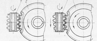
Let's start getting acquainted with the design of blocks with a simple block , which is a wheel rotating around its axis, with a groove around the circumference for a cable (rope, chain) Fig. 1 and it can be considered as an equal-armed lever, in which the arms of forces are equal to the radius of the wheel: OA =OB=r. Such a block does not provide a gain in strength, but allows you to change the direction of movement of the cable (rope, chain).
A double block consists of two blocks of different radii, rigidly fastened to each other and mounted on a common axis in Fig. 2. The radii of the blocks r1 and r2 are different and, when lifting a load, they act like a lever with unequal shoulders, and the gain in force will be equal to the ratio of the lengths of the radii of the block of larger diameter to the block of smaller diameter F = Р·r1/r2.
The gate consists of a cylinder (drum) and a handle attached to it, which acts as a block of large diameter. The gain in force given by the gate is determined by the ratio of the radius of the circle R described by the handle to the radius of the cylinder r on which the rope is wound F = Р r /R.
Let's move on to the method of lifting a load with blocks. From the design description, all blocks have an axis around which they rotate. If the axis of the block is fixed and does not rise or fall when lifting loads, then such a block is called a fixed block, a simple block, a double block, a gate.
The movable block has an axle that rises and falls together with the load (Fig. 10) and is intended mainly to eliminate the bending of the cable at the point where the load is suspended.
Let's get acquainted with the device and method of lifting a load; the second part of a simple lifting mechanism is a cable, rope or chain. The cable is made of steel wires, the rope is made of threads or strands, and the chain consists of links connected to each other.
Methods for hanging a load and gaining strength when lifting a load with a cable:
In Fig. 4, the load is fixed at one end of the cable, and if you lift the load by the other end of the cable, then to lift this load you will need a force slightly greater than the weight of the load, since a simple block of gain in strength does not give F = P.
In Fig. 5, the worker lifts the load by a cable that goes around a simple block from above; at one end of the first part of the cable there is a seat on which the worker sits, and by the second part of the cable the worker lifts himself with a force 2 times less than his weight, because the worker’s weight was distributed into two parts of the cable, the first - from the seat to the block, and the second - from the block to the worker’s hands F = P/2.
In Fig. 6, the load is lifted by two workers using two cables and the weight of the load will be distributed equally between the cables and therefore each worker will lift the load with a force of half the weight of the load F = P/2.
In Fig. 7, workers are lifting a load that hangs on two parts of one cable and the weight of the load will be distributed equally between the parts of this cable (as between two cables) and each worker will lift the load with a force equal to half the weight of the load F = P/2.
In Fig. 8, the end of the cable, by which one of the workers was lifting the load, was secured on a stationary suspension, and the weight of the load was distributed into two parts of the cable, and when the worker lifted the load by the second end of the cable, the force with which the worker would lift the load was doubled less than the weight of the load F = P/2 and lifting the load will be 2 times slower.
In Fig. 9, the load hangs on 3 parts of one cable, one end of which is fixed and the gain in force when lifting the load will be equal to 3, since the weight of the load will be distributed over three parts of the cable F = P/3.
To eliminate the bend and reduce the friction force, a simple block is installed in the place where the load is suspended and the force required to lift the load has not changed, since a simple block does not provide a gain in strength (Fig. 10 and Fig. 11), and the block itself will be called a movable block , since the axis of this block rises and falls along with the load.
Theoretically, a load can be suspended on an unlimited number of parts of one cable, but in practice they are limited to six parts, and such a lifting mechanism is called a polyspast , which consists of a fixed and movable clip with simple blocks, which are alternately wrapped around a cable, one end fixed to a fixed clip, and the load is lifted for the second end of the cable. The gain in strength depends on the number of parts of the cable between the fixed and movable cages; as a rule, it is 6 parts of the cable and the gain in strength is 6 times.
Conclusions.
The article examines the real-life interactions between the blocks and the cable when lifting a load. The existing practice in determining that “a fixed block does not provide a gain in force, and a movable block gives a gain in force by 2 times” erroneously interpreted the interaction of the cable and the block in the lifting mechanism and did not reflect the entire variety of block designs, which led to the development of one-sided erroneous ideas about block. Compared to the existing volumes of material for studying a simple block mechanism, the volume of the article has increased by 2 times, but this made it possible to clearly and intelligibly explain the processes occurring in a simple lifting mechanism not only to students, but also to teachers.
Literature:
- Pyryshkin, A.V. Physics, 7th grade: textbook / A.V. Pyryshkin. - 3rd ed., additional - M.: Bustard, 2014, - 224 p.,: ill. ISBN 978–5-358–14436–1. § 61. Application of the lever equilibrium rule to the block, pp. 181–183.
- Gendenstein, L. E. Physics. 7th grade. In 2 hours. Part 1. Textbook for educational institutions / L. E. Gendenshten, A. B. Kaidalov, V. B. Kozhevnikov; edited by V. A. Orlova, I. I. Roizen. - 2nd ed., revised. - M.: Mnemosyne, 2010.-254 p.: ill. ISBN 978–5-346–01453–9. § 24. Simple mechanisms, pp. 188–196.
- Elementary textbook of physics, edited by academician G. S. Landsberg Volume 1. Mechanics. Heat. Molecular physics. - 10th ed. - M.: Nauka, 1985. § 84. Simple machines, pp. 168–175.
- Gromov, S. V. Physics: Textbook. for 7th grade general education institutions / S. V. Gromov, N. A. Rodina. - 3rd ed. - M.: Education, 2001.-158 p.,: ill. ISBN-5–09–010349–6. §22. Block, pp.55 -57.
Inclined plane.
As we know, it is easier to roll a heavy barrel along inclined walkways than to lift it vertically. The bridges are thus a mechanism that provides gains in strength.
In mechanics, such a mechanism is called an inclined plane. An inclined plane is a flat, flat surface located at a certain angle to the horizontal. In this case, they briefly say: “inclined plane with an angle.”
Let's find the force that must be applied to a mass load in order to uniformly lift it along a smooth inclined plane with an angle . This force, of course, is directed along the inclined plane (Fig. 5).
Let's select the axis as shown in the figure. Since the load moves without acceleration, the forces acting on it are balanced:
.
We project on the axis:
,
where
.
This is exactly the force that needs to be applied to move the load up an inclined plane.
To evenly lift the same load vertically, a force equal to . It can be seen that, since . An inclined plane actually gives a gain in strength, and the smaller the angle, the greater the gain.
Widely used types of inclined plane are wedge and screw.
The golden rule of mechanics.
A simple mechanism can give a gain in strength or distance, but cannot give a gain in work.
For example, a lever with a leverage ratio of 2:1 gives a double gain in strength. In order to lift a weight on the smaller shoulder, you need to apply force to the larger shoulder. But to raise the load to a height, the larger arm will have to be lowered by , and the work done will be equal to:
i.e. the same value as without using the lever.
In the case of an inclined plane, we gain in strength, since we apply a force to the load that is less than the force of gravity. However, in order to raise the load to a height above the initial position, we need to go along the inclined plane. At the same time we do work
i.e. the same as when lifting a load vertically.
These facts serve as manifestations of the so-called golden rule of mechanics.
The golden rule of mechanics. None of the simple mechanisms provide any gains in performance. The number of times we win in strength, the same number of times we lose in distance, and vice versa.
The golden rule of mechanics is nothing more than a simple version of the law of conservation of energy.
Formula for calculating the efficiency of a pulley block
As always, efficiency shows the ratio of work performed to work expended. For further calculations, let's turn a little to practice.
- First.
While reading, you most likely immediately had a question about what deflection angles are we talking about? Indeed, modern chain hoists simply do not have them. These corners have no practical meaning. You can safely replace the sine from the formula with one. - Second.
As mentioned earlier, the value of q is extremely small relative to f. In real conditions it is omitted. Also, the diameter of the chain hoist thread is of very little importance.
Well, actually, we only have the friction force of the pulley block on its bushing. Thus, the main importance when choosing a pulley is the quality of the materials from which it is made , or rather the materials of the bushing.
The following values of the efficiency of the pulley block are used in the calculations:
- 100% is an unattainable ideal;
- 97% is the average value when using bronze bushings in rolling bearings;
- 95% - average value when using plain bearings;
- 93% and less - very dusty places, very high temperatures or aggressive environments of use.
Don't forget that we are still looking at one single video, and we have more than one or two.