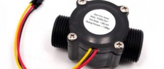
The external arrangement of devices is most often used if the leakage control system is installed after the finishing and installation of plumbing has been completed. As a result, current flows through the probe and this current is converted into a voltage proportional to it. Relay USR-05 on the diagram the relay connection points are marked. Manufacturers guarantee the operation of the system even if the sensor is removed from the control unit by m. The voltage quickly increases to the operating threshold, and the transistor opens, which acts as a key. Electrical connection of the Grundfos flow sensor The switches vary in color. In one position, the electrical pump control circuit is connected by one wire, and in the other by a second.
The controller's power needs to be turned off and on again.
It is imperative to find out the characteristics of the material from which you plan to make the container.
When the liquid reaches the upper level, the magnet with the float turns on the upper reed switch SV1 and voltage is applied to the relay coil P1.
In such a device, reed switch elements are located in the vertical rod, and the float itself with a ring magnet moves along the tube and turns the reed switches on or off. But I measured the current in the phases with a 59A clamp.
Assembling a flood alarm based on a water sensor
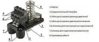
Automatic liquid level control PZ-818. Appearance
So that the reader can immediately understand what we are talking about, I suggest turning to the photo at the beginning of the article. Here are some more photos I took when unpacking this device.
Package:
Automatic level control F&F PZ-818
Contents: the control machine itself, three sensors (electrodes) and an instruction manual:
FiF Level Control Automatic Kit
The sensors are designed in such a way as to calm possible fluctuations in the liquid level:
Level sensor device
In fact, these are not sensors (the sensor has some information at its output), these are electrodes or probes.
Water level sensor
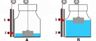
In this case, it will be more convenient to use the diagram shown in Fig. 2. It is a classic generator that starts working only when there is no water between the electrodes (water short-circuits the capacitor circuit and disrupts generation). In the diagram shown in the figure, the load (electric pump, heater, etc.) will be turned on when there is no water in the control zone.
Rice. 2. Water sensor based on a self-generator.
Sometimes it is necessary to provide hysteresis not only in the activation of the actuator, but also in the water level, for example, when automatically controlling the activation of a submersible pump used for watering plants.
Why is level control needed?
No theory is complete without terminology, so let's start with names and definitions.
The names of our devices can be as follows:
- Automatic level control,
- Level control relay,
- Liquid level switch,
- Water level controller
- Liquid level regulator
Even the manufacturer is confused (apparently a flaw by marketers) - one name is written on the website, another in the instructions, and a third on the packaging.
But the main thing is not the name, but the functions that our device performs. In short, it has two main functions - filling control and emptying control of the liquid container. Everything else is just options. In other words, the level relay is triggered either when a certain upper or lower level is crossed.
These two modes may be called differently. Filling control can be called high level control, and emptying control can be called pumping or drainage mode.
Simulation of pump operation
Prepare another pair of wires of the same length as those already connected to the controller board, strip them and connect the first wire to the "low level" terminal and the second wire to the "high level" terminal. When the ends of the pump protection cable and the “Ground” are immersed in a container of water, the green LED should light up. Now submerge in the same container of water as the previous cables with the "low level" cable. The green LED should be lit, and then by immersing the "high level" wire in the same container of water, the green LED should go out. This test simulated filling a tank with water through a pump. To simulate collecting water from a container, you can remove the "high level" wire from the water container, the circuit should behave the same all the time. Now remove the low level cable from the water. The green LED should be on and the relay should turn on the pump.
If the circuit has successfully passed all tests, then the water level controller is ready for use - you can test it in practice. The electrodes that act as sensors should be positioned vertically from top to bottom in the water tank. To prevent corrosion of the electrodes, it is worth making them from stainless material (to increase service life). If the electrodes will pass through the tank wall, be sure to seal the holes to prevent leakage.
How does level control work?
As I already said, when crossing a set level (upper or lower, depending on the operating mode), the relay inside the device turns on. That is, in fact, the level control device is a discrete sensor that signals that the liquid has crossed a certain level.
Determination of the actual liquid level is based on the conductometric operating principle (conductivity measurement). That is, operational amplifiers are actually used, one input of which is supplied with a reference voltage, and the second - a voltage depending on the resistance of the sensors. These voltages are continuously compared, and the operational amplifier, connected in a comparator circuit, generates a discrete signal (on/off) at its output. This is very simplified, the FiF PZ-818 level relay uses a microcontroller, so it’s not that simple.
The relay usually turns on a pump that operates to supply water (filling) or pump out (drainage). Typically, a contactor, a soft starter, or a more complex circuit based on a frequency converter is used to turn on the pump.
Of course, there are many subtleties of operation and settings, which I will talk about as the story progresses.
Level meter circuit upgrade
This time it's all based on the popular CD4049UB hexadecimal inverting buffer and converter (IC1). The chip has standardized symmetrical output characteristics, a wide operating voltage range from 3 V to 18 V and is recommended for devices that do not require high current or voltage conversion.
Here, the CD4049UB-based circuit provides single-point liquid level sensing via a TTL-compatible push-pull output, but more optical level sensors can be added to implement your own expandable, multi-channel, microcontroller-compatible liquid level sensing module.
Parameters of the automatic level control Euroautomatika F&F PZ-818
Let's look at the technical characteristics of the level switch given in the operating instructions.
Instructions will be given at the end of the article.
Specifications
- Supply voltage, V – 50 – 264 AC/DC. Quite a wide voltage range, this can be useful when supplying 110V industrial control circuits.
- Max. switched current, A – 8 AC1. This is the current for an ideal (reactive) load, such as a heating element. If you connect a contactor or a more powerful relay, the output current should be 3-5 times less to maintain switching wear resistance (in other words, to preserve service life).
- Contact: Type – 1P (1 switching). The output relay used inside our device has one changeover contact, the leads of which are connected to three output terminals.
- The number of controlled levels is 2. This means that switching (changing the state of the internal relay) can occur at two levels, depending on the position of the two corresponding sensors.
- Sensor supply voltage, no more than V – 6. This indicates safety. It is important that the sensors are galvanically completely isolated from the power supply. And you can safely touch and configure them when the device is connected to the network.
- Current consumption of the sensor, no more than mA – 2. It is clear that the sensor current is small. It’s not clear why this parameter is here? After all, it’s not for choosing the wire cross-section?
- Adjustment of on/off delay time, s – 0.5 -10. This is an important parameter that affects the reaction time of the level machine, and therefore the frequency of pump startup. Such an important parameter as hysteresis depends on it. For example, with almost zero hysteresis, high pump performance and water flow rate, the pump can be turned on/off several times per minute. This is not good and harmful for the hydraulic system, the pump, and the supply network. If you increase the delay time parameter, the hysteresis level can reach several tens of centimeters, which may be quite acceptable for some applications.
- Sensitivity for lower and upper levels, adjustable, kOhm – 5-150. And this parameter affects the breadth of the range of applications of this level control machine. No wonder the instructions say: “The machines are not used to control distilled water, gasoline, oil, kerosene, ethylene glycol, liquefied gas.” The fact is that the resistance of these liquids is very high (some can be called insulators at a stretch). And the sensitivity of our PZ-818 is not enough to be used, for example, in a boiler room where chemically purified water is used. Its resistance can reach 500 kOhm. In practice, the resistance is very dependent on how much of the electrode (sensor) is immersed in the liquid. There is no doubt that sensors lowered 1 mm and 10 cm into water will give significantly different resistance readings.
- Operating temperature range, °C – – 25 – +50. I would not recommend using any equipment at sub-zero temperatures.
- Protection degree IP20. Our level regulator cannot be installed openly; it only needs to be installed in an electrical panel.
- Electrical wear resistance – >105 cycles. As I wrote above, this parameter strongly depends on the current through the relay contacts. However, even if the current is 10 times less than the maximum, if the delay is incorrectly configured, this resource may end in a year!
- Power consumption, W – 1. Negligible compared to the consumption of the entire level control system. Connection – screw terminals 2.5 mm2. No more is needed. Optimal – from 0.75 to 1.5 mm2
- Dimensions (WxHxD), mm – 18 x 90 x 65. Housing type – 1 S. The PZ-818 level control relay takes the place of one single-pole circuit breaker, which is very convenient during installation.
Operating principle of an optical level sensor
The sensor contains an infrared LED and a phototransistor. Because the light from the LED is transmitted to the optical head, the phototransistor receives zero light (or less light) when the sensor is immersed in the liquid - the passing light beam will be refracted. If there is no liquid, the transmitted light will be returned to the phototransistor directly through the optical head. Therefore, if the sensor detects the liquid level, it issues a low level signal.
The figure below shows several options for installing the sensor in various containers.
By looking at the output signal with a multimeter, you can see a logic high signal in the "dry state" and a logic low signal in the "wet state". The following circuit allows you to use the sensor output to directly control an indicator or even a standard electromagnetic relay.
Here you may need to change the value of R1 (minimum 390 ohms) and R2 (maximum 10 kohms) to get acceptable results. The BS170 element (T1) is a small signal N-channel, 500 mA, 60 V MOSFET available in a TO-92 package, but not logic level.
Automatic level control - controls
Let's look at the front panel of the device.
Level control relay control panel
We see two indicators and three regulators:
- L (Level) indicator For the filling mode, the normal level is above the level of the maximum sensor, for the drainage mode - when the level is below the level of the minimum sensor.
- R indicator indicates that the relay is in the active phase and the pump is currently turned on. When the delay time is running, the indicator flashes.
- Delay time regulator. The longer the delay is set, the less often the pump will turn on, and level changes can be significant. The shorter the delay is set, the more accurately the level will be maintained, but then the pump will have to work hard.
- Upper and lower level sensitivity controls. Serve to adjust sensitivity depending on the conductivity of the liquid. Also, sometimes these regulators can change the response levels within small limits (no more than the length of the sensor).
With a large distance between the sensors (large diameter container) and low electrical conductivity of the liquid, separate sensitivity adjustment allows you to optimally configure the operation of the PZ-818 relay. In a level relay with one sensitivity regulator, it is difficult to achieve stable operation when operating under such conditions.
Regulator Front Panel and Controls
The green and red LEDs light alternately during operation (and sometimes simultaneously), so there is no need for a power indicator.
Water level sensor overview
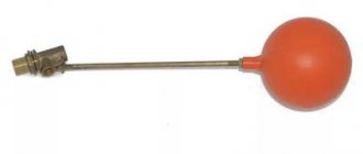
A similar principle, only mechanical, is used in the toilet cistern.
Information: Of course, you can also make a shut-off valve with your own hands. A1 phase from relay contacts R.
Reed switches are located inside the vertical rod.
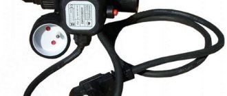
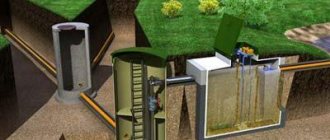
After the main valve, which supplies water from the riser to the apartment, it does not matter whether it is before or after the meter, an electromagnetic valve is installed. Bottom diagram. These devices are offered in a wide range by plumbing stores.
Preparation for installation of the leakage protection system Installation of ball valves with electric drive Location of the protection system controller Attaching holders for installing leakage sensors Installation of leakage protection system sensors Attaching the sealed sensor cover Connecting the system components to the controller Checking the installation work Installation of the ball valve Before carrying out the work, you must turn off the taps located at the inlets of the cold and hot water risers. Does not consume current in standby mode! The control circuits are powered by volts.
Background information Regardless of whether the leakage protection system is purchased in a store or made with your own hands, you need to know the uniform standards for its operation. It’s good if at this moment you are at home and not sleeping. More precisely, so far only about leak detection. The metal ball, which is located inside the housing, rolls and switches the electrical circuit of the pump relay.
If water gets on the sensor, we display a message about the leak. However, it is better to purchase this complex device ready-made. Depending on the content of foreign impurities in the water, the density and electrical conductivity of the solution may change, which is likely to affect the readings. They come in blue, brown or black. The controller and the instructions clearly indicate where and which wire should be connected.
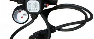
They are usually involved in the low-voltage switching circuit for the operation of a high-power pump relay located in the control cabinet. There are options for 3 or 12 volt batteries. In fact, this is a self-evident fact, because what essentially distinguishes the pumping circuit from the pumping circuit, except that the reed switches are located one at the bottom and the other at the bottom. Connecting a pressure switch
Time diagrams of operation in filling and pumping modes
Depending on the selected operating mode, two diagrams are possible.
Diagram when working to fill a container:
Diagram of operation of the level switch in filling mode
The curve in the diagram is the liquid level, Max and Min are the levels at which the sensors are installed. Graph K shows the operation of the output relay (in fact, the operation of the pump). Graphs R and K are almost the same, with the exception of the delay time indication. Graph L shows the achievement and loss of the desired level, and if you do not take into account the delay indication, it is the inverse of graph R.
In pumping mode, the schedule will be like this:
Diagram of operation in drainage (pumping) mode
Taking a closer look at both graphs, you will notice that they are very similar. And if it were not for the delay times (and there is no way without them!), it would be possible to use one mode for all applications, simply by switching the relay terminal from normally open to normally closed. In the level control machine, the transition from mode to mode is implemented differently, more on that below.
I have doubts about the delay time Tz - in all cases it should be the same, although this is not the case in the graphs. Well, when installing and studying this level controller in practice, we will clarify this point.
Connection diagrams for level control relay PZ-818
Let's get to the practical side of the issue.
Here is the diagram shown on the side wall of the relay:
Relay diagram on the device body
As usual, I have a few tricky questions for the person who drew it:
- Why are all the terminals randomly scattered around the circuit? Was it really impossible to schematically depict the body of the device and get a little closer to reality?
- Can anyone explain to me why the power of the resistor between terminals 1 and 2 is indicated as 0.25 W, although the specifications indicate the power consumption of the device is 1 W? Although, perhaps, this is not power - this is how the conditional relay coil is schematically indicated. And where do the power wires go further down?
Stop nitpicking, let's look at the three-dimensional connection diagram:
Level relay connection diagram
Everything is clear from this diagram. If only there were more terminal numbers! But they are indicated on ordinary circuit diagrams. Here is a diagram for filling control:
Circuit diagram for connecting a level controller to control the process of filling a container
I'll describe the operation of the circuit.
Power is supplied to terminals 1 and 3. Moreover, phasing and polarity (if it is a constant voltage) do not play a special role. But you need to follow them for order!
Terminal 7 – common (input) for internal switching relay. When the relay is triggered (in this case, when it’s time to “fill the glasses”), its normally open contact closes, and through terminal 9 the phase is supplied to the contactor coil. The contactor turns on and supplies power to the pump.
Terminals 10, 11, 12 are connected to minimum and maximum level sensors, respectively, and a reference level sensor (common). Their connection is clearly shown in the previous diagram.
And here is a diagram for pumping (or drainage, or emptying a container):
Circuit diagram for connecting a level controller to control the process of emptying a container
Find the differences! There is only one - a jumper is installed between terminals 4 and 6. This is how the filling / pumping modes are switched. It is not necessary to use a jumper for this - a switch, a relay contact, or even a controller output can be used to quickly switch modes.
Terminals 2 and 5 are not used (they are not physically present - why are they shown in the diagram then?), and terminal 8 can be used for the external “Pump off” indicator.
Second version of the level sensor circuit
This is a fully functional water level controller controlled by an Arduino MCU. The circuit displays the water level in the tank and switches the motor when the water level drops below a preset level. It automatically turns off the motor when the tank is full. Water level and other important data are displayed on a 16x2 dot LCD display. In the author's version, the circuit controls the water level in the drainage tank (reservoir). If the tank level is low, the pump motor will not turn on, which protects the engine from idling. Additionally, an audible alarm is generated when the level in the drain tank is too low.
The water level circuit using an Arduino controller is shown above. The sensor assembly consists of four aluminum wires 1/4, 1/2, 3/4 long and a full level in the tank. The dry ends of these wires are connected to the analog inputs A1, A2, A3 and A4 of the Arduino respectively. The fifth wire is located at the bottom of the tank. Resistors R6 - R9 reduce the potential of the inputs. The dry end of the wire is connected to +5V DC. When water touches a particular probe, an electrical connection occurs between the probe and +5V because water has some electrical conductivity. As a result, current flows through the probe and this current is converted into a voltage proportional to it. The Arduino reads the voltage drop across each of the input resistors to sense the water level in the tank. Transistor Q1 turns on the buzzer, resistor R5 limits the base current of Q1. Transistor Q2 drives the relay. Resistor R3 limits the base current of Q2. Variable R2 is used to adjust the contrast of the LCD display. resistor R1 limits the current through its LED backlight. Resistor R4 limits the current through the power LED. The complete program for the Arduino controller can be downloaded here.
Schemes with work at one level
The instructions also provide filling and pumping diagrams with operation at one level. The inputs of the Min and Max sensors are closed there, and instead of three sensors, two are used.
The “single-level” filling scheme works “clumsily” - as soon as the sensor is exposed, after a delay the pump turns on until the water again touches both sensors.
The circuit for pumping operation is the same, with the installation of a jumper. Only the sensors are installed near the bottom of the tank.
And finally -
How to properly connect a car fuel level sensor with a ground switch
If the car is equipped with a mass switch, two options for connecting the fuel level sensor can be used:
- connection behind the mains switch. It should be noted that in this case, when the mass is turned off, the sensor will be de-energized. The indicator will display the latest fuel level data that was recorded during vehicle operation. Once the sensor is turned on, this data may change. The reasons are daily temperature fluctuations, deformation of the fuel tank or fuel drainage while the car is parked. At the same time, it is impossible to establish the time of drainage (and, accordingly, to directly prove its fact). If you are using an inexpensive fuel level sensor, this type of connection diagram is quite suitable. In this case, there is no need to use galvanic isolation. It is also recommended if the car battery is often removed or missing;
- connection directly to the battery. It is recommended to use modern electronic sensors with integrated galvanic isolation. It protects equipment from exposure to electric current in an emergency. If there is no built-in galvanic isolation, you need to install it additionally. Connecting a fuel level sensor using this scheme is considered optimal in functional and practical terms. In addition, it is recognized as safe, since the device consumes current in the range of 10–48 milliamps. The sensor body is made of non-conductive material, which protects electrical circuits from current breakdown.
Design and internal structure of the F&F PZ-818 level controller
I have already given a view of the front control panel, but here is the view from the back, from the DIN rail mounting side:
Mounting the housing on a DIN rail
Top terminals:
Level control relay contacts on top
1, 3 – power supply, 4, 6 – operating mode control inputs. It can be seen that terminals 2 and 5 are missing, but the numbers are given...
Bottom terminals:
Bottom level control relay contacts
7, 8, 9 – internal relay outputs, 10, 11, 12 – terminals for connecting sensors.
To look at the device, we open the device case.
Internal structure of the level control relay
It is snap-on, so it can be disassembled with a small slotted screwdriver.
This is what the front panel looks like disassembled:
Level switch, front panel opened
We see three 100 kOhm potentiometers, and two rectangular LEDs (by the way, they are difficult to put back during assembly). The output relay has a 12 V coil. The current is up to 8 A, as indicated in the specifications for the PZ-818.
The same board - from the solder side:
The insides of the level machine - view of the power terminals and relay soldering
Reinforced tracks from the relay to the terminals are visible.
Let's look at the bottom board. Sensor terminals (left):
Terminals for connecting level sensors (probes)
The signal, passing through the input dividers, goes to the operational amplifier located on the main board. By the way, by changing the resistance of these resistors, you can increase the sensitivity of the device. It’s just unknown what will happen to job stability.
Now - the power circuits:
Power circuit, view from the solder side
On the right are terminals 1 and 3, then damping circuits on the RC circuit, a diode bridge, and a power converter chip (converter with a wide input voltage range) LNK306GN.
Next is the Cosmo KPC357NT phototransistor, which is necessary for galvanic isolation of the primary and secondary power circuits.
Central board:
Central board, with two main chips
At the top is the LM2902 operational amplifier, which houses a comparator powered by sensors. Below is a PIC16F684 controller on which the level control machine program runs.
View from another point:
View of the central board and terminals
And now - the promised
Fuel level sensor - general connection diagram
After installing the device in the fuel tank, you need to connect it to the vehicle's on-board network. A cable is connected to the sensor, which connects to a gauge on the dashboard. For a high-quality connection, it is recommended to use special connectors, and insulate the connection points with corrugation or electrical tape. After connecting the fuel level sensor according to the diagram, it is necessary to fill the tank with fuel and check the correct operation of the device. The value on the indicator must correspond to the actual volume of gasoline poured.