Although the development of modern technology in mechanical engineering has made it possible to replace many metal parts with more practical solid plastics and composites, the need for steel elements still remains. Metal processing technologies also remain relevant, but new methods and tools are emerging in this area. Thus, thread rolling, which replaced traditional cutting, made it possible to optimize the production process for manufacturing parts and improve the quality of the screw connection in principle.
Features of the rolling process
The technology refers to a variety of transverse knurling, but in this case the emphasis is on the use of rollers in relation to cylindrical workpieces. The method also focuses on the principles of extruding a screw profile, which allows for a softer thread formation, adhering to the technical specifications down to the smallest dimensional parameters. The features of the thread rolling process include the following:
- No destruction of the internal structure of the metal workpiece. This also applies to corrosion-resistant, heat-resistant and special types of steel. It is the soft deformation effect that eliminates unwanted processes of excess pressure on the metal.
- The outer layers of the workpiece are strengthened, and the load capacity of the element increases.
To these advantages it is worth adding the characteristics of the screw profile itself. Due to the sliding of the knurling, the relief surface acquires optimal hardness and roughness with a microstructure favorable for contact with the texture of adjacent surfaces.
Thread rolling reduces costly downtime
Photo source: Dormer Chip-free thread forming is an efficient and productive process.
Rolling as an alternative to thread cutting is a method, although not new, but still relatively undeveloped. It has a number of advantages compared to traditional methods. Of the many ways to form a thread, the most common is cutting the workpiece using a tap (internal thread) or a die (external thread).
Read this article to learn how thread rolling can reduce costly downtime.
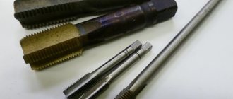
Thread rolling with a rolling tap, also known as cold forming or extrusion, involves creating threads by plastic deformation instead of cutting with a conventional tap.
Using this method offers several significant advantages over tapping. These include: increased speed because cold forming is faster than conventional threading, longer tool life, stronger threads (higher shear strength) than cut threads, no chips, and a less rough surface.
Chip-free thread forming is an efficient and productive process that can be used in a wide range of materials such as steel, stainless steel, non-ferrous metals and aluminum (source: Dormer)
By and large, there are various options for cutting taps without grooves - fluteless taps. However, they all have the same principle: a thread of a certain geometry is applied to the tap, which has deforming protrusions, or vice versa, a cylindrical thread is made at intervals at different points along the circumference of the tap with deforming protrusions located in them. These projections, distributed over the surface of the tap at a certain interval, form a thread as the tool is immersed in the material.
Chipless process eliminates breakdowns due to chip accumulation
One of the key differences between this process and thread cutting is the absence of chips. Consequently, there is no need to periodically retract the tap to clean it up to avoid chip buildup and possible tool failure, leading to costly downtime and rebuilding of workpieces damaged when the tap is removed—often using an EDM machine.
Tests have shown that during the rolling process, not only the tensile strength of the thread increases, but also the quality of its surface, hardness and wear resistance. Therefore, higher speeds are recommended for rolling taps than for corresponding cutting taps of the same material.
To enable manufacturers to take full advantage of thread rolling, ]Dormer[/anchor] has developed a comprehensive line of chipless taps. Manufactured from high quality cobalt high speed steel (HSS-E), all of these tools are designed for productive threading on a variety of workpiece materials. In addition, they can be equipped with a groove for supplying coolant to the cutting edge.
The most important recommendation for chipless thread rolling is the use or addition of extreme pressure additives to the cutting fluid. Lubricants maintain the smoothness so necessary in such processes. Lack of lubrication when rolling threads can cause dry friction of metal on metal and, as a result, become a possible cause of tool failure.
When using a cutting tap, the drilled hole is sized to match the tip of the finished thread, and the tool removes material between the tips, creating the profile of the thread. However, rolling does not remove the original material, so the diameter of the drilled hole for an equivalent thread must be slightly larger. Thus, the thread profile is formed by “extruding” the workpiece material with a tap.
The material deformed during the rolling process becomes stronger, and the surface formed becomes smoother, which means an increase in the service life of the thread. Finally, it provides design engineers with the opportunity to evaluate the use of smaller diameter fasteners.
Source of material: translation of the article Thread forming reduces costly machine downtimes , ETMM
Original article author: Simon Winstanley, Dormer Tools
There are no related entries.
Knurling with double roller machines
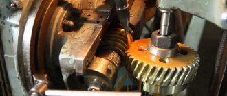
In the implementation of this method, semi-automatic thread rolling machines are used, which make it possible to produce metric, trapezoidal and other screw profiles with high accuracy. Complex corrugations are also produced on running parts and fine-module helical wheels. The process of thread formation itself is carried out by rolling in a profile that is applied previously. This is a kind of rolling of notches on the thread, formed due to the forced rotation of the rollers. During movement, the machine also performs radial movement of functional elements using force from a hydraulic drive. In turn, the cylindrical workpiece is located between the rollers on the supporting part or in the chuck of the gripping device. It rotates under the influence of friction force, which is formed when the rollers come into contact with the surface of the part and increases as the deforming profile is introduced.
Characteristics of roller segments
The rolling rollers themselves are only an integral part of a universal machine, however, according to the principle of their operation, they can also act as independent cutters. In any case, it is important to consider two main parameters when choosing this segment - tensile strength and profile diameter. As for strength indicators, thread rolling with rollers can withstand up to 1400 MPa, maintaining an accuracy of up to 0.1 mm. The disadvantage of this method is precisely the limitation on the thickness of the cylinder. For example, the range of diameters of processed parts of standard format varies from 1.5 to 15 mm on average. The thread pitch will be up to 2 mm, and the length will be about 80 mm. At the same time, the technology turns out to be quite expensive, given the complexity of manufacturing rollers and machines that serve the working infrastructure.
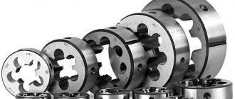
Design and parameters of knurling rollers
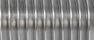
Knurling rollers are cylindrical disks made of alloy steel grades, on the surface of which there is a certain type of thread or ring-type turns. The dimensions of the knurling roller depend on the following factors:
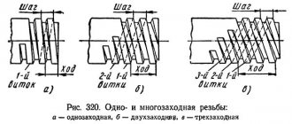
- type of rolled thread (single or multi-start);
- rolling method (tangential, axial, radial);
- applied thread rolling equipment (semi-automatic, automatic, head).
The tangential rolling method is highly productive and is performed by feeding two rollers, each of them having its own peripheral speed, at the same speed or in special centers. There are cylindrical and backed knurling rollers. The latter, in addition to intake and calibrating elements, also have a discharging element, which speeds up the cutting process and makes it possible to process 2 workpieces simultaneously or apply it on both sides. The axial rolling method is used when it is necessary to roll threads onto a workpiece of large length. The most common knurling method is radial. In this case, cylindrical rollers are used for rolling external and internal threads. They must comply with the requirements of GOST 9539-72. Most often, products with mounting holes of 45, 54, 63 or 80 mm are used.
The material for the manufacture of rolling tools is steel, which contains chromium, vanadium, molybdenum and other refractory elements: Kh12M, Kh6VF, Kh12F1, 6Kh6V3MFS, R18, R6M5, R18. In this case, the surface hardness should be within 58÷61 HRC. The knurling roller can withstand pressure up to 1400 MPa, while the manufacturing accuracy is 0.1 mm.
The main parameters of the product are as follows:
- diameter of the external thread profile, indicated in mm;
- internal diameter along the depressions;
- profile angle in degrees;
- width;
- groove dimensions - width and depth;
- thread pitch and length.
Knurling with holders and cylindrical heads
This equipment is used in combination with a cylindrical non-driven tool. Universal metal-cutting units can be used as operating equipment. For example, as a machine for rolling threads with holders and cylindrical heads, lathes, turning-turret and spindle automatic machines can be used. The main technological feature of the use of the equipment itself can be called the completeness and high accuracy of the process. The same heads provide finishing capabilities that support high demands on thread runout, alignment and stability. That is, after applying this operation, there is no longer a need for special modifications. But along with the advantages of using holders and heads for knurling, there are also disadvantages, which include low productivity, which excludes the possibility of using the method in large-scale production format.
Knurling with dies
This technology, on the contrary, is successfully used in hardware production for the serial production of fasteners with normal accuracy. The use of flat dies is characterized by high productivity, while requiring the connection of equipment that is simple in design. This ensures both the reliability of the working process and versatility in the manufacture of parts of different standard sizes. For example, the range of diameters for thread rolling in this case will be 1.7-33 mm. The maximum thread length will be 100 mm, and the pitch distance is within 0.3-3 mm. One of the negative aspects of using dies is the low hardness of parts, since the equipment only works with materials whose tensile strength does not exceed 900 MPa. On the other hand, dies of special modifications make it possible to perform knurling on self-tapping screws and screws in one threaded pass.
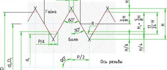
What is the difference between metric thread and pipe thread?
The main difference between the two types of threads is the shape of the threaded crest and grooves. The metric profile is based on an equilateral triangle, so all angular dimensions for this type of cutting are equal and amount to 60 degrees, while for an inch pipe the angular dimensions are 55 degrees. All metric thread parameters are measured in millimeters, while pipe thread sizes are calculated in inches. Another nuance is that the dimensions of the pipe threads take into account the thickness of the walls of the product, which vary depending on the operating pressure for which certain pipes are designed.
Metric thread parameters are presented in millimeters, and inch thread parameters are presented in inches
Products with a metric type of cutting must be marked with the letter “M”. Metric profile sizes range from 1 mm to 600 mm. Threaded metric pitch can range from 0.075 mm to 3.5 mm. Products with the smallest pitch of metric threads are used for fine work (measuring tools), with a medium pitch - for creating parts and assemblies operating in conditions of constant vibration. The largest metric threads are used in the construction of heavy load-bearing structures.
This is interesting! For pipes with inch knurling, the pitch is calculated in the form of the ratio of the number of turns per inch of length of the knurled thread.
Inch threads, however, are found in industry and everyday life more often than metric threads. Pipe threads are almost universally measured in inches - a more universal unit of measurement for the water and gas industry.
Since different types of knurling have different angles at the tips, it is impossible to combine two types of threads, even those with identical dimensions. To make the transition from metric to pipe threads, special shaped elements are required - adapters.
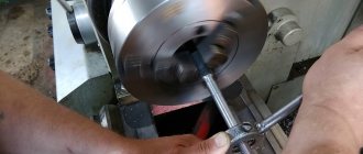
Manual thread rolling
Mechanized machines with electric drives do not always give the expected accurate results. They perform well in in-line processing and when performing complex tasks involving the deformation of solid metal. But, for example, knurling on knitting needles is best done on a manual machine without a drive. Manual force will be enough to extrude small turns on a cylindrical metal surface, while maintaining high accuracy. The work uses compact machines, the structure of which is formed in two parts - a bed and working equipment with three rollers. The process of rolling threads on spokes is performed through a handle connected to the head through a shaft. The spoke is integrated into a collet mechanism with an adjustable socket. In this case, it is important to provide in advance the extreme values for the diameter of the workpiece. On average, cylindrical parts with a thickness of 1.5-3 mm are suitable for such machines.
TO
category:
Installation of ventilation systems
P
publication:
Mechanism for rolling threads on water-gas pipes
H
read more:
Machines and mechanisms for bending steel water and gas pipes
Mechanism for rolling threads on water-gas pipes
In recent years, thin-walled water and gas pipes have been widely used for sanitary systems; the wall thickness of thin-walled pipes, depending on their diameters, ranges from 2 to 10 mm compared to the wall thickness of normal pipes from 8 to.5 mm.
When cutting a normal thread at the end of a pipe, a part of the metal is cut off with a threading tool and a reduced wall thickness is left at the junction of the pipe. To avoid weakening of the pipe wall, thread rolling is used when processing thin-walled pipes. For these purposes, instead of thread-cutting heads, NPT thread-rolling dies equipped with special thread-rollers are used.
When rolling threads on pipe cutting machines (S225, VMS2B, etc.), an adapter spindle is attached to the spindle flange, onto which a replaceable die holder is attached. A thread rolling die of the required size is inserted into the die holder. Thread rolling should be done at speeds slightly higher than when cutting threads on pipes with tangential dies, for which on these machines, by changing the pulleys in the V-belt drive, the spindle speed is increased to 420 rpm. Due to operation at high speeds, the knurling rollers need cooling, for which a tank with an electric pump is installed near the machine, supplying a cooling emulsion to the knurling head.
Promotional offers based on your interests:
Specialized mechanisms are used to roll threads on water and gas pipes and drains in the sanitary industry.
The STD129 mechanism is designed for rolling pipe threads on thin-walled steel water and gas pipes (GOST 3262 - 62) using rolling dies such as VNGT and NPT. The mechanism consists of a frame, a drive, a clamping mechanism, electrical equipment with a control panel, pneumatic equipment, a stop, and a cooling system. The bed is used to place the main components of the mechanism on it. The main elements of electrical and pneumatic equipment are located in the niches of the frame. The drive consists of a housing in which a hollow spindle is installed, one of the ends of which ends in a flange. A rubber rolling head is attached to the spindle flange. The thread-rolling head is connected to the clamp using crackers. One end of the clamp is pivotally connected to a bracket mounted on the drive housing, and the other to a pneumatic cylinder mounted on the drive housing. With the help of a pneumatic cylinder, the thread rolling head is opened and closed. A pulley is installed at the second end of the spindle. Inside the drive housing there is a second V-belt drive pulley driven by a flange electric motor. A slider with a rod and a spring is installed inside the hollow spindle. The slide has a conical hole for installing a countersink in it, which is used for chamfering at the end of the internal cavity of the pipe. The clamping mechanism consists of a housing in which dovetail-shaped guides are made. The body of the clamping mechanism is connected by a lever to a pneumatic cylinder, thanks to which it can perform reciprocating movement. The pipe is clamped in the pneumatic clamp using a pneumatic cylinder. First, by rotating the flywheel, set the required gap between the jaws of the mechanism and the clamped pipe. The design of the clamping mechanism includes adjustment elements that allow centering of the pipe being processed. To roll a thread of a given length onto a pipe, there is a stop on the mechanism. The stop consists of a housing in which a plunger is located, controlled by the pneumatic equipment system of the mechanism. The plunger is connected to the lever and allows you to set the required pipe extension in the clamping mechanism. Operation on the mechanism is carried out as follows: the automatic switch on the control panel is turned on, as a result of which electrical voltage is supplied to the mechanism. The switch is set to the position corresponding to the specified thread rolling mode, depending on the diameter of the pipe. Then the drive motor is turned on, the pump drive motor drives the coolant to the thread rolling head. Depending on the length of the rolled thread, press the “Cycle” button on the control panel. Then the clamping electromagnet is turned on, the pipe is clamped in a pneumatic vice and the clamping mechanism is fed to the thread-rolling head. When rolling a thread of the required length, the cam of the clamping mechanism presses the limit switch and the thread-rolling head opens, but the clamping mechanism will continue to move until another limit switch is activated, after which the movement of the pipe clamping mechanism will be reversed. Having reached the rearmost position, the clamping mechanism acts on the corresponding limit switch, the pneumatic clamp is released, the finished pipe blank is removed from the mechanism, and the mechanism itself is ready to receive a new pipe blank.
Rice. 1. Mechanism STD129: a - general view; - side view; c - kinematic diagram
The mechanism can operate in both adjustment and automatic modes.
The STD487 mechanism is designed for rolling pipe threads on water and gas steel pipes manufactured in accordance with GOST 3262 - 62 using a thread-cutting head with rolling rollers. The mechanism consists of a frame, a spindle box, a thread-rolling head, a carriage, electrical equipment and a cooling system tank. An electric motor is located inside the frame. On the body of the spindle box there is a handle for controlling the thread rolling head and turning on the pneumatic cylinder of the pneumatic clamp. The drive from the electric motor to the threading head is carried out through a V-belt transmission and a pair of gears. The threading head is attached to the spindle box using two tangential locks. On the body of the thread rolling head there is a switch ring that controls the closing and opening of the rolling rollers of the thread rolling head. The ring is connected to the handle by a rod. A lever with a rod is attached to the end of the control handle. The end of the rod is connected by a bracket to the carriage. When the carriage moves forward (during thread rolling), the bracket acts on the nut located on the rod. The rod, in turn, turns the lever and the handle, which ensures that the rollers of the thread rolling head automatically open at the end of the thread rolling process at the end of the pipe. The pipe is clamped using a steering wheel with a self-centering vice located on the carriage. The pipe is installed in a vice until it stops, located in front of the thread-rolling head. The movement of the carriage with the pipe clamped in a vice at the initial moment of the cycle is carried out using a pneumatic cylinder.
The operation of the pneumatic cylinder is controlled by an air distributor, which is kinematically connected to the control handle of the thread rolling head. After the rollers of the thread rolling head are closed and the first threads are rolled, the carriage moves forward forcibly. After the thread of the required length is rolled on the pipe, the carriage, through the bracket and rod, will force the handle to be installed in the extreme right position through the lever. The rollers of the thread rolling head will separate, and under the influence of the air distributor, the pneumatic cylinder will force the carriage to return to its original position. Using the steering wheel, the pneumatic clamping jaws diverge and the finished pipe blank is removed from the mechanism. Thread rolling rollers need to be cooled during the thread rolling process, for which purpose a cooling system tank is located behind the mechanism frame. The coolant supply is forced, using a pump driven by an autonomous electric drive. The coolant is drained into the reservoir by gravity.
Rice. 2. Mechanism STD487: a - general view; b - kinematic diagram
Promotional offers:
Read more: Machines and mechanisms for bending steel water and gas pipes
TO
category: — Installation of ventilation systems
Home → Directory → Articles → Forum
“On-pass” knurling technology
Special technique for forming long threads over 250 mm. Features of this method include axial feeding of the workpiece, as well as the formation of a lifting angle at the rollers along the screw line relative to the knurling contour. If we talk about the machines used, then the optimal one would be a unit with an inclined spindle, the design of which will allow the use of roller segments with ring threading. The screw configuration will also be varied - left and right, single and multi-start profiles with strict adherence to a certain pitch are possible. The maximum rolling diameter of this type of thread reaches 200 mm with a pitch of 16 mm. In practice, threaded rods with trapezoidal or metric profiles are often made in this way. To achieve high processing speeds, the machines are equipped with a special transmission, the outboard bearings of which are forcibly lubricated by a built-in mechanism. This allows you to achieve a rotation speed of about 600 rpm.