We connect the relay to the water main
You need to connect the pressure switch to water first, and to electricity second. Setting up the relay is the very last, third stage.
Let's assume that everything turned out great and we found that piece of pipe with a thread to which we need to screw the pressure switch. Do you know how to make reliable threaded connections? If yes, then good. If not, you'll have to practice. Tangit Unilok thread is now on sale. This is a pretty cute and convenient thing. It is more convenient than flax for sealing threaded water connections, but is quite expensive. We'll use it!
The procedure for connecting the pressure switch to the water line for dummies (specialists don’t have to read it)
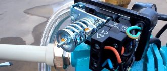
So, having prayed, let's begin. There are small tricks when sealing threads with flax or tangit. Tangit is wound, obviously, onto the thread that is located on the tube. We place this tube with the end, that is, the end facing us. It turns out that we are looking directly at the end on which we will screw whatever it is. Let's estimate approximately how much thread we will use. We take the tangit thread and start wrapping it. We start this process not from the end, but towards the end, stepping back from the edge to the distance that will be inside the nut. In the diagram above, I indicated the approximate position from which to start with a green arrow. When winding tangit, twist the thread clockwise (red arrow in the diagram), looking at the end of the pipe. The first loop should firmly secure the thread. so that it does not stretch or unravel. Next, we follow the instructions for the tangit, that is, make sure that the thread does not lie inside the thread grooves.
You need to wind it fairly evenly and tightly. Do not try to wrap it so that you get a whole tumor of tangitis. This is where you really need some experience. Wrapping it too little is bad. It will leak. Too much - don't tighten the nut, you'll crease the thread and it will leak again. Dont be upset! It will turn out well. No - you will practice. Let's say they wrapped it up. We begin to wind up the relay
Let's wind it up slowly! very slowly and carefully. First with your hands, but not for long
As soon as we feel resistance, we begin to work with a wrench. The first sign that everything is fine is that the tangit nut screws on quite easily. The presence of the thread should be felt, but in moderation. We carefully monitor how the relay nut is screwed on. If it screws onto the tangit, then that’s just great. Unfortunately, it may happen that you see that the tangit under the nut forms loops, gathers and comes out of the thread. This is bad. In this case, I suggest tightening it a little more and, if the situation with the loops worsens, then it is better to unscrew the relay and redo the entire winding. In this case, it is better to free the thread from the old thread and do everything clean.
Let's assume everything worked out, there were no loops, or there was one small one that formed when we had practically screwed everything together. Then screw the relay all the way. But not too much! Let's take a breath. There is a high probability that everything will be fine and there will be no leaks.
Connecting the device to power supply
The next stage of installing a water pressure sensor is connecting the device to the electrical network. First you need to find two groups of contacts on the relay, which are usually closed, but should open when the maximum pressure value is reached. Typically, the location of these contacts is indicated in the instructions for the pressure switch. If there are no instructions, any electrician can help you decide.
The photo clearly shows the location of the contact pairs to which power is supplied. When the maximum pressure value is reached, the contacts open and the pump turns off
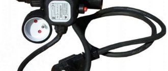
Note! To connect the relay to the power supply, it is recommended to use a cable whose characteristics correspond to the power of the pump.
Now you should screw the wire strands to the free contacts of each pair. You should not connect the contacts of one pair in this way, as this will lead to a short circuit. The ground wire is connected to a special screw on the relay body. This screw is marked with the corresponding symbol.
This symbol conventionally denotes a grounding contact. Failure to ground an electrical appliance is a dangerous safety violation that can lead to an accident and even injury.
Then the pressure switch must be connected to the pump. To do this, use a piece of wire of suitable length. One end of its cores is screwed to the free contacts of the relay, the other - to the contacts of the pump. It is recommended to observe the color of the cores. The relay and pump ground contacts can also be connected, although this is not considered necessary.
After this, you need to check the operation of the system. If, as water is drawn, the pressure on the pressure gauge increases, when a certain maximum is reached, the pump turns off, and as water is consumed, the pressure decreases, the relay is installed correctly.
Review of popular models
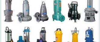
There are two types of pressure switches: mechanical and electronic, the latter are much more expensive and are rarely used. The market offers a wide range of devices from domestic and foreign manufacturers, making it easier to select the required model.
RDM-5 Gilex (15 USD) is the most popular high-quality model from a domestic manufacturer.
Characteristics
- range: 1.0 - 4.6 atm.;
- minimum difference: 1 atm.;
- operating current: maximum 10 A;
- protection class: IP 44;
- factory settings: 1.4 atm. and 2.8 atm.
Genebre 3781 1/4″ (10 cu) is a budget model made in Spain.
Characteristics
- body material: plastic;
- pressure: upper 10 atm;
- connection: threaded 1.4 inches;
- weight: 0.4 kg.
Italtecnica PM/5-3W (13 cu) is an inexpensive device from an Italian manufacturer with a built-in pressure gauge.
Characteristics
- maximum current: 12A;
- working pressure: maximum 5 atm;
- lower: adjustment range 1 - 2.5 atm.;
- upper: range 1.8 - 4.5 atm.
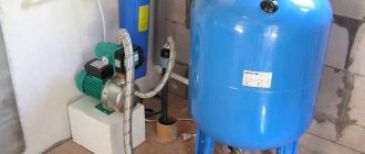
The pressure switch is the most important element in the water intake system, providing automatic individual water supply to the house. It is located next to the hydraulic accumulator, the operating mode is set using adjusting screws inside the housing.
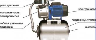
When organizing an autonomous water supply in a private house, pumping equipment is used to lift water. In order for the water supply to be stable, it is necessary to select it correctly, since each type has its own technical characteristics and features.
For efficient and trouble-free operation of the pump and the entire water supply system, it is necessary to purchase and install an automation kit for the pump, taking into account the characteristics of the well or well, the water level and its expected flow.
A vibration pump is chosen when the amount of water spent per day does not exceed 1 cubic meter. It is inexpensive, does not create problems during operation and maintenance, and its repair is simple. But if water is consumed from 1 to 4 cubic meters or water is located at a distance of 50 m, it is better to purchase a centrifugal model.
Typically the kit includes:
- an operating relay, which is responsible for supplying and blocking voltage to the pump when the system is emptying or filling; The device can be immediately configured at the factory; self-tuning for specific conditions is also allowed:
- a collector that supplies and distributes water to all points of consumption;
- pressure gauge for measuring pressure.
Manufacturers offer ready-made pumping stations adapted to specific requirements, but a self-assembled system will work most efficiently. The system is also equipped with a sensor that blocks its operation during dry running: it disconnects the engine from power.
Sensors for protection against overload and integrity of the main pipeline, as well as a power regulator, ensure safe operation of the equipment.
Features and purpose of the pressure switch
The water pressure switch for the pump is designed to ensure the normal operation of the entire water supply system. As a rule, almost no automatic control devices are installed at pumping stations. A certain level of control is provided by the relay itself.
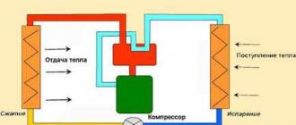
The pump control relay is a small unit in a plastic box with springs inside. Springs are necessary to adjust the two extreme positions of the system. One position is responsible for turning the system on, and the other for turning it off.
The relay itself works in conjunction with a hydraulic accumulator. It consists of a metal tank filled with water. Inside the tank there is a bulb made of rubber or a special membrane. Air is pumped into this bulb. The air expands the membrane walls and creates the required pressure in the tank.
As the amount of water in the accumulator decreases, the bulb receives less resistance and the pressure drops. At certain pressure levels, the well pump activation relay will do its job. The pump will turn on and begin pumping water until the pressure in the container is equalized to the highest level.
Thus, a relay for a water pump is perhaps the most necessary device that completely controls its operation and ensures the autonomy of all processes. All you need to do is connect and configure the relay. These devices are connected to water supply and electricity.
There is also special automation for pumps; the pressure switch in this case is an electronic device with a regulator or screen. The electronics feature more flexible and simpler setup. Yes, and it has many more functions.
It is worth noting that pressure switches or its analogues are used not only at domestic pumping stations. It is also used to regulate the operation of heating systems and even the fuel supply in a car.
The relay for the heating pump does not operate on pressure, but by measuring the temperatures of the incoming and outgoing liquid. Which, however, is completely natural. After all, in heating it is not so much the pressure that is important, but the efficiency of heating radiators or heating circuits.
The thermostat for the heating pump has thermometers for measuring the temperature of the liquid. You only need to set the upper and lower temperature thresholds, and the relay itself will then control the operation of the system.
Few people know where the fuel pump relay is located or even what it looks like. Meanwhile, it is the fuel pump relay that allows you to protect the system from possible breakdowns. Typically, the fuel pump relay is located under the glove compartment.
It is designed to respond to the pressure level in the fuel pump. Too high a level causes the relay to switch and stop completely.
Connecting the pressure switch to the water supply system
When installing a relay in a water intake system, the following rules must be observed.
- The hydraulic accumulator for water supply systems and the point of connection of the device to the water supply are located nearby - this will avoid switching the pump during sudden short-term pressure surges.
- When installing, you should take into account the temperature regime - some models operate only in warm conditions.
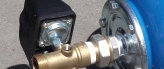
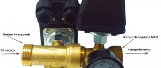
- To simplify installation, modern surface-type pumps are equipped with a fitting to which a relay and pressure gauge can be directly connected.
Connecting a pressure switch to a submersible pump can be done in two ways:
- The device is connected to water pipes through a tee using an adapter fitting.
- Before connecting the hydraulic accumulator to the submersible pump, a five-pin fitting is connected to it, the connected devices (hydraulic accumulator, pressure gauge, relay) and the water main are connected at one point.
Choosing an installation location
For correct operation of the equipment, the pressure switch must be connected to the pump in such a way as to avoid the influence of turbulence and sudden pressure changes when the pumping equipment is turned on and during its operation. The best place for this is in the immediate vicinity of the hydraulic accumulator.
Before installing the pressure switch, pay attention to the operating mode recommended by the manufacturer, in particular, the permissible temperature and humidity values. Some models can only work in heated rooms.
In the classic scheme for connecting a pressure switch to a deep-water pump for an autonomous water supply, the following equipment is installed in front of the relay:
- pumping unit,
- check valve,
- pipeline,
- flow shut-off valve,
- drainage to the sewer,
- filter for preliminary (coarse) cleaning.
When using many modern models of surface-type pumping units, installing a water pressure switch for a pump can be much simpler: block installation is carried out when the relay is installed together with the pump. The pumping unit has a special fitting, so the user does not need to independently search for the most suitable installation location. The check valve and filters for water purification in such models are often built-in.
Connecting the pressure switch to a submersible pump can also be done by placing the hydraulic accumulator in the caisson and even in the well itself, since waterproof design of the control equipment is often required and the operating conditions of the pressure switch may allow its location in such places.
The connection diagram for a pressure switch and a pumping station with a surface pump differs slightly from the diagram with a submersible unit in the sequence of arrangement of some elements
Obviously, the choice of installation method and location depends on the design of the equipment; usually all recommendations in this regard are indicated by the manufacturer in the accompanying documentation.
Electrical connection diagram
Depending on the needs of the user and his financial capabilities, you can choose one of the methods of connecting the deep pump to the electrical network.
Without automation
Without auxiliary control devices, the pump is connected using a pre-installed electrical outlet with a grounding contact. The pump is also grounded. For this purpose, the main bus of the house is used, connecting to the existing ground loop of the building.
A three-core cable is used to supply electricity to the outlet. The power supply voltage of the submersible pump is 220V. 380-volt or 150-volt outlets cannot be used.
Via pressure switch
To reduce the cost of a set of pressure equipment, you can use a connection diagram for a well pump only with a pressure switch without a control unit. The device turns off the pump when the pressure reaches a maximum, and starts it when the pressure drops to a minimum.
Using control unit
When selecting an automation model, you first need to find out what protective system is already installed in the pump by the manufacturer. Modern devices are already protected from overheating and idle operation. Sometimes the equipment is equipped with a float mechanism. Taking this data into account, you can choose one of three automation options - simple, with a second or third generation electric control unit.
The simplest protection is most often used for automatic water supply. The control unit here is assembled from three devices:
- Dry running blocker. It will turn off the device, which operates without water, preventing overheating. Sometimes the additional installation of a float switch is allowed. It performs the same functions, turning off the pumping equipment when the water level drops, preventing it from overheating. The devices may seem primitive, but they provide effective protection for the electric motor.
- Hydraulic accumulator. Without it, it will not be possible to provide automatic water supply. The hydraulic tank works as a water storage tank. Inside there is a working mechanism - a diaphragm.
- Pressure switch equipped with a pressure gauge. This device allows you to configure the operation of relay contacts.
It is not difficult to equip pressure equipment with simple automation with your own hands. The principle of operation of the system is simple: as water flows, the pressure in the hydraulic tank decreases. When the minimum value is reached, the relay starts the pressure equipment, which pumps water into the storage tank. When the pressure in the hydraulic accumulator reaches its maximum, the relay device turns off the installation. As water is consumed, the cycle repeats.
The pressure limits in the storage tank are adjusted using a relay. In the device, using a pressure gauge, the minimum and maximum response parameters are set.
In second-generation automation, the connection is made through an electrical unit with a set of sensors. They are mounted directly on pressure equipment, as well as inside the water supply network, and allow the system to function without a hydraulic tank. The impulse from the sensors goes to the electronic unit, which controls the system.
Operation of pressure equipment with this scheme for connecting a submersible well pump to automation:
- Liquid accumulates only in the water supply where one of the sensors is installed.
- When the pressure drops, the sensor sends a pulse to the control unit, which starts the pump.
- After reaching the required pressure of the water flow in the water supply, the pump is turned off according to a similar scheme.
To install such automation, you will need basic knowledge of electrical engineering. This and the previous protection work almost identically - based on water pressure. However, the electric unit with sensors is more expensive, which is why it is not so popular among consumers. Even when using automation, you don’t have to use a hydraulic tank, although if there is a power outage, you won’t be left without water. There is always a reserve left in the drive.
Third generation automation is reliable, high quality and expensive. Its installation allows you to significantly save on electricity due to ultra-precise tuning of the electric motor. The connection diagram for advanced automation to a deep well pump is very complex, so you should contact a professional to connect it. But it provides complete protection of the motor from various breakdowns, for example, overheating during dry running or burning of the windings during power surges.
The unit operates from sensors without a hydraulic tank. Efficiency is achieved through fine adjustments.
How to adjust correctly (with hydraulic accumulator)
Before setting the relay, you need to remove the cover, under which there are two springs with nuts: large and small. By turning the large nut, the lower pressure in the hydraulic accumulator (P) is adjusted. By rotating the small nut, the pressure difference (ΔР) is set. The starting point is the position of the large spring, with the help of which the lower pressure limit is set.
Before you begin setting up the pressure switch for the pump, you must remove the top cover from the device, which hides the large and small springs
After the required air parameter has been reached in the accumulator, the tank should be connected to the system and turned on, observing the readings of the water pressure gauge. Please note that the technical documentation for each pump indicates operating and maximum pressure indicators, as well as the permissible water consumption rate. These values must not be exceeded when configuring the relay. If during system operation the operating pressure of the accumulator or the limit value of the pump is reached, it is necessary to turn off the pump manually. The maximum pressure is considered reached at the moment when the pressure stops increasing.
Fortunately, regular household pump models are not powerful enough to pump the tank to its maximum capacity. Most often, the difference between the set on and off pressures is 1-2 atmospheres, which fully ensures optimal use of the equipment.
Once the water pressure gauge shows the required lower pressure, the pump should be turned off. Further adjustment is made as follows:
- Carefully rotate the small nut (ΔP) until the mechanism starts to work.
- Open the water to completely empty the system of water.
- When the relay turns on, the lower value will be reached. Please note that the pump activation pressure should be approximately 0.1-0.3 atmospheres higher than the pressure reading in an empty hydraulic tank. This will protect the “pear” from premature damage.
- Now you need to rotate the large nut (P) to set the lower pressure limit.
- After this, the pump is turned on again and waited until the indicator in the system rises to the desired level.
- All that remains is to adjust the small nut (ΔP), after which the hydraulic accumulator can be considered adjusted.
Adjustment diagram
Here is a diagram that is suitable for most devices:
The pressure switch for the pump is adjusted using two nuts: large and small. They must be handled very carefully so as not to damage the device.
Is a hydraulic accumulator really necessary?
A reasonable question: is it possible to do without a hydraulic accumulator? In principle, this is possible, but with a conventional automation unit the pump will turn on and off very often, reacting even to insignificant water flow. After all, the amount of water in the pressure pipeline is small, and the slightest flow of water will lead to a rapid drop in pressure and an equally rapid increase when the pump is turned on. It is precisely so that the pump does not turn on every time you “sneeze” that they install a hydraulic accumulator, at least a small one. Since water is an incompressible substance, air is pumped into the accumulator, which, unlike water, is highly compressible and acts as a kind of damper that regulates the accumulation and flow of water. If there is no air in the accumulator or too little air, then there will be nothing to compress, that is, there will be no accumulation of water.
Ideally, the capacity of hydraulic accumulators should be only slightly less than the debit of your water source, and the pump, in this case, will turn on only when some fairly decent supply of water has been used up, i.e. very rarely, but for a long time. But then it will be very expensive.
Now pumping stations with improved automation units with built-in dry-running protection have appeared on sale, which smoothly start and stop the pump and regulate its power depending on the set pressure. It is believed that, in principle, they do not need a hydraulic accumulator. But all this works well only in the absence of voltage surges, which our outback and holiday villages cannot boast of. And, unfortunately, stabilizers do not always save you from this disaster. In addition, the price of such a station is very often much higher than usual, which, it seems to me, does not justify itself.
Relay classification
There are two types of relays based on the principle of operation - mechanical and automatic. When purchasing this mechanism, you need to consider what functions this device should perform.
In addition, automatic relays, although easier to operate, are less durable than mechanical ones. Therefore, most buyers opt for the mechanical option.
In addition, relays are sold either built into the pumping station or separately from it. Therefore, you can select a relay based on individual characteristics that will improve the operation of all equipment.
Mechanical type
- Mechanical pressure switch SQUARE with dry running protection. The pressure generated by this device ranges from 1.3 to 5 bar. The required current for the relay to operate effectively is 10 A.
- Pressure switch Cristal. The current required to operate this device is 16 A. The permissible pressure limit in the water supply system is 4.5 bar.
Electronic
Electronic relays are more susceptible to breakdowns due to the fact that when water is supplied, various small particles appear in it, which damage the equipment. To prevent this from happening, a special filter is placed at the supply inlet, which purifies the water and does not prevent damage to the device. An electronic device is better than a mechanical one in that it does not allow the pumping station to run idle.
After pressing the button to turn off the water supply, the electronic relays operate for another 16 seconds. This function is necessary to ensure that the device operates for a longer time.
An electronic relay is easier to install and configure. To reconfigure its operation, the entire system does not need to be disassembled; you just need to configure the necessary parameters on the electronic display using the appropriate buttons.
- Pressure switch PS-15A with dry running. This electronic device operates in a pressure range from 1 to 5 bar. The current is 12 A. In addition to the listed characteristics, the device has built-in factory settings and full protection against dry running.
- Pressure switch PS-2-15. Has factory settings and dry-running protection. The possible pressure limit in the water supply system is 5.6 bar, the current is 10 A.
Is it possible to use your pressure switch with your pump?
The pressure switch connects not only to electricity, but also to water. For water connection there is a nut that is rigidly attached to the relay. This means that when screwing the pressure switch to the pump, you will have to twist the relay itself. Thus, first of all, figure out whether you have the ability to turn this relay clockwise on the pump? Will it fit? Will it hit other pipes or the pump housing itself?
We will assume that this issue has been resolved positively, since otherwise you need to look on the spot and, for example, take care of some kind of extension cord or something similar.
The pressure switch has a water inlet that is not quite standard in diameter. For most household relays this is a quarter inch. For professional relays, the connection diameter may be larger. You should definitely take care of this issue and, if necessary, buy a brass adapter for the required diameter.
Previously, in the production of automatic pumping stations, a special and completely standard part was used, popularly called a herringbone. This is such a nice piece of brass pipe, 10 or 12 centimeters long and 1 inch in diameter. The herringbone is screwed at one end onto the outlet pipe of the pump and has standard “outputs” for connecting a pressure gauge, pressure switch, accumulator tank and the water line itself. Now everything has become much more complicated. There are pumps where the pressure switch is screwed directly onto the pump or into very inappropriate, at first glance, places. This variety makes my job of writing detailed instructions quite difficult.
Mixed connection diagram of the automation unit and pressure switch
To prevent the operation of a pumping unit in dry running mode, which could lead to failure of a functioning pumping station, an automation unit is used. Uninterrupted operation of the device supplying water from the well is ensured by installing a pressure switch. An additional device is assigned the functions of protecting the system in the event of an unexpected drop in pressure.
Variants of automatic control stations differ in their operating principle. The level sensor installed during installation inside the well is characterized by increased reliability. An electronic device monitors changes in the volume of liquid in the water shaft, giving a command to stop the operation of the mechanisms when the indicators critically decrease. The simplest protection that can prevent the operation of a pump unit in dry running mode is a float switch.
The combined connection diagram provides for the installation of the following elements:
- deep well pump of centrifugal action;
- expansion tank with a capacity of more than 50 liters, preventing water hammer in the water main;
- a check valve that makes it easier to start the electric pump by retaining water in the system, preventing reverse outflow;
- a pressure switch designed to monitor changes in fluid pressure;
- axial pressure gauge;
- a float sensor that allows or prohibits the start of the power unit depending on the water level in the well;
- control station.
Connecting the pump to the automation unit prevents operation of the equipment in dry running mode. In a space not filled with liquid, the mechanisms run idle, reducing the life of the pump unit.
Relay adjustment
When purchased, the relay is configured for a specific switching mode, standard values are 1.4 and 2.8 atm, that is, at 2.8 atm. the pump will be turned off and turned on if the pressure is less than 1.4 atm. Usually, when installing a device into a system, you need to select a response threshold - for this you need to know what pressure the pump in the well provides.
If the pressure of the well pump is 2 atm, and the standard value of 2.8 atm remains in the relay, then the pump will never turn off (it physically cannot create a pressure that reaches the response threshold) and after intensive work will go to eternal rest. A less tragic situation is when the pump can produce a pressure of 5 atm, and the relay turns it off at 2.8 atm. In this case, the system does not work efficiently and it is advisable to install a device that matches the pressure of the well water pump.
To take measurements when adjusting the relay, you need a pressure gauge; the work consists of the following steps.
- Water begins to be drained from the system, and the pump activation pressure is recorded on the pressure gauge.
- Close the valves and record the pressure gauge readings at which the pump turns off.
- Adjust the device with a large screw, periodically turning the water on and off until the desired lower pressure value is obtained.
- Then they proceed to adjusting the range that sets the upper pressure with a small screw. The water is also periodically turned on and off until the required value is obtained.
Device and principle of operation
To ensure water supply to a private home, the relay is connected simultaneously to two systems: water supply and electrical network. It is advisable to connect the device via a separate line, then longer and uninterrupted operation of the equipment will be guaranteed. The main elements of an electromechanical water pressure device for a pump:
- plastic case;
- couplings for connecting cables;
- terminals for connecting the ground wire;
- contacts for connecting power wires;
- manual switch button;
- pressure adjustment nut and spring;
- base;
- fitting for connection to the system.
All control is carried out through a membrane that is in contact with the water supply and is a thin plate. If the pressure in the system reaches its maximum value, the membrane reacts instantly and the water pump is turned off.
A low pressure reading will not prevent the spring from bending the plate in the opposite direction, and the pump will turn on. The spring pressure switch block for the pump consists of two parts. The first includes a spring that controls the minimum pressure value and restrains the main water pressure.
The adjusting nut adjusts the minimum pressure. The other unit is a spring that controls the maximum value, and adjustment is carried out with a special nut. The principle of operation of the hydraulic relay is that the membrane, under the influence of water flow, closes and opens contacts that turn the pump on or off.
This happens due to the fact that the relay is in a circuit with a hydraulic accumulator, in which a membrane separates water and compressed air. When the pump operates, water presses on air through a membrane, creating some pressure, which decreases as the liquid flows. The adjustment is carried out based on the pressure gauge readings:
- upper pressure threshold - 2.8 kg/cm²;
- the lower value is 1.4 kg/cm².
If the setup is carried out correctly, the equipment will operate automatically without user intervention. From time to time it will be necessary to clean the contacts, since they oxidize during prolonged use.
Why assemble the pumping station yourself.
First of all, it seems to me that you should assemble the pumping station yourself if you already have some of its components, usually the most expensive ones. This is a pump and a hydraulic accumulator. Because the cost of the pump is approximately half the cost of the pumping station, respectively, the hydraulic accumulator is approximately a third. That is, it makes no sense to buy a new pumping station if your accumulator is crushed in winter or the pump burns out for some reason. You can buy both separately and simply replace what is broken; fortunately, the pump fasteners and the hydraulic accumulator mounting platform are, as a rule, standard and you can connect one to the other without much difficulty.
Another reason to assemble a pumping station yourself may be a discrepancy between your requirements and the characteristics of the equipment of the finished pumping station. For example, you need a pump with higher pressure or water flow than the pumping stations offered to you, and what suits you in terms of characteristics does not suit you in terms of cost or reliability. Either the dimensions of the pumping station are too large for the place where you are going, or you are not satisfied with the capacity of the hydraulic accumulator, well, etc. You just need to keep in mind that the final cost of the pumping station may well be much more than what you planned.
The third, most common option is when you are forced to assemble a distributed pumping station due to very... As a rule, in this case, a powerful submersible pump is used, and a hydraulic accumulator with an automation unit is installed somewhere at home.
Equipment selection rules
For autonomous water supply systems, you should choose a relay for household use
Such systems are characterized by basic parameters: the maximum pressure value is no more than 5 atmospheres, operating pressure values are usually in the range from 1.4 to 2.8 atm. When setting up the relay, it is important to remember that the magnitude of the difference between the limit values (settings on the springs) directly affects the volume of water that the pump, with such settings, will pump into the accumulator reservoir. A large volume means that the pumping unit will turn on less often, but the technical capabilities of the system must not be exceeded in this regard. You should not save excessively by purchasing a relay of unknown origin.
Such equipment will not only fail to ensure correct operation, but will also most likely cause damage to other equipment included in the system. Connecting the automatic pump and pressure switch together with a high-quality pressure gauge installed next to the relay will allow you to monitor the operating parameters of the system and help detect violations at an early stage, when there are still no external manifestations.
We have information about hydraulic accumulators here
What models are there and what is important when choosing them
We talked about ways to clean a well in this material.
Application and design
In order to maintain a stable pressure in the water supply system of a country house, two devices are needed - a hydraulic accumulator and a pressure switch. These mechanisms are connected to the pump through a pipeline - the pressure switch is located in the middle between the supercharger and the hydraulic accumulator. However, individual configurations can be mounted to the pump housing.
A hydraulic accumulator is a reservoir divided into two parts by a stretchable membrane. In one half, air is located under a certain pressure, and liquid is pumped into the second half. The water pressure in the accumulator and the volume of liquid that can be pumped there are regulated by the amount of air pumped in.
The more air, the higher the pressure in the system, but the less water in the tank. As a rule, it is possible to pump no more than half of the total volume of water into the container, that is, no more than 50 liters of liquid can be pumped into a 100-liter hydraulic accumulator.
For the normal functioning of household appliances, an indicator of 1.4 atm-2.8 atm is required. To maintain the pressure in this range, a pressure switch is needed. This device has two response limits - upper and lower.
When the lower limit is reached, the relay starts the pump, which pumps water into the accumulator, and the pressure in the circuit increases. When the upper limit is reached, the relay turns off the pump. Water is gradually consumed from the storage tank, the pressure in the system slowly drops until it reaches the lower limit again. The pumping station will start working again.
The relay consists of two components - an electrical part and a hydraulic component. An electrical component is a group of contacts that make and break switches that turn the pumping equipment on and off. The hydraulic group consists of a membrane that exerts pressure on a metal base, and a large and small spring, with the help of which the range of settings of the pump can be changed.
The outlet of the hydraulic group with an external thread or with an American-type nut is located on the rear side of the device. The inputs of the electrical component are also located on the back of the case, and the block itself with terminals for connecting wires is hidden under the cover.
Settings
To configure the pressure switch, it is necessary to set the operating pressure in the system. To do this, after assembling the circuit, the equipment should be turned on and wait for automatic shutdown when the relay is activated. After this, the roof is removed and the settings are performed in the following sequence:
- Loosen the nut that presses the smaller spring.
- Set the required minimum pressure value (pump activation parameter). Rotating the large spring nut clockwise increases the set pressure value, and in the opposite direction decreases it.
- Having opened the tap, they empty the system, monitoring the automatic response threshold using a pressure gauge. If the result is unsatisfactory, adjust the setting.
- The pump shutdown parameter can be adjusted in the same way by rotating the nut on the second (smaller) spring.
To supply water to a house from a borehole or well source, pressure equipment is required. Submersible models are most often used because they are easy to use and unpretentious. To independently assemble a water supply system, you need to have an idea of the diagram and connection features of a submersible pump so that it functions correctly.
Practical examples of relay configuration
Let's look at cases when turning to adjusting the pressure switch is really necessary. This usually happens when purchasing a new device or when frequent pump shutdowns occur.
You will also need to configure it if you received a used device with lost parameters.
Connecting a new device
At this stage, you should check whether the factory settings are correct and, if necessary, make some changes to the operation of the pump.
Image gallery
Photo from
Stage 1 – equipment preparation
Stage 2 - adjusting the switching value
Stage 3 - adjusting the shutdown value
Stage 4 – testing the system operation
To track the progress of work, it is recommended to write down all received data on a piece of paper. In the future, you can return the initial settings or change the parameters again.
The pump stopped turning off
In this case, we forcibly turn off the pumping equipment and proceed in the following order:
- We turn it on and wait until the pressure reaches its maximum level - let's say 3.7 atm.
- We turn off the equipment and lower the pressure by draining water - for example, to 3.1 atm.
- Lightly tighten the nut on the small spring, increasing the differential value.
- We check how the cut-off pressure has changed and test the system.
- We configure the optimal option by tightening and loosening the nuts on both springs.
If the reason was due to incorrect initial settings, it can be solved without buying a new relay. It is recommended to regularly, once every 1-2 months, check the operation of the pressure switch and, if necessary, adjust the on/off limits.
Situations that do not require adjustment
There can be many reasons when the pump does not turn off or turn on - from a blockage in the communications to engine failure. Therefore, before you start disassembling the relay, you should make sure that the rest of the pumping station equipment is working properly.
If everything is fine with the other devices, the problem is in the automation. Let's move on to inspecting the pressure switch. We disconnect it from the fitting and wires, remove the cover and check two critical points: the thin pipe connecting to the system and the contact block.
Image gallery
Photo from
The connection pipe to the hydraulic tank is clogged
Cleaning the relay inlet
Electrical contacts are clogged
Cleaning the contact block
If cleaning measures did not help, and adjusting the position of the springs was also in vain, most likely the relay is no longer suitable for further use and should be replaced with a new one.
Suppose you come across an old but working device. Its adjustment occurs in the same order as setting up a new relay. Before starting work, make sure that the device is intact, disassemble it and check that all contacts and springs are in place.
How to connect a pump to a well and water supply
Before installing a submersible pump, thorough cleaning of the well shaft is required. For this purpose, using a temporary pump, liquid is pumped out of the column until all sand and impurities are removed. To protect the pressure device from water hammer, you need to install a non-return valve on it.
The pump is connected to the well in the following sequence:
- The pipeline is being installed. When connecting the pump to a rigid pipe between it and the main line that transfers water to the consumer, it is better to insert a small piece of flexible hose to dampen the vibration of the electric motor.
- A cable, electrical wire, or hose are connected to the device.
- The device is smoothly lowered into the well.
- When the pump reaches the bottom, it is raised half a meter to a meter.
- The cable is rigidly fixed, the cable is connected to the electrical network, the hose is connected to the rest of the system and laid in the mounting channels.
Well pump kit
Effective operation of the individual water supply system at the dacha is ensured by equipping the pumping unit with the following elements:
Well pump kit.
- Submersible or surface type pump.
The purpose of the device is the uninterrupted supply of water from a deep shaft. - Power cable.
The length of the electrical wire is determined by the distance of the downhole equipment from the place of possible connection to the network. Safety is ensured by the presence of a special grounding conductor. - Hydraulic accumulator.
The storage tank increases the service life of the pumping unit, compensating for sudden changes in pressure. Functions in conjunction with the previous element. - Control system.
Electronic devices control the operation of the pump unit.
The minimum factory configuration of the device is not designed to connect the pump to the automation. The water storage tank and control unit are considered optional equipment and must be purchased separately.
Connecting the pump unit to the electrical network is carried out in several ways. The difference lies in the number of mounted elements. The following options exist:
- Direct connection. Performed without installing additional devices. The required components are a submersible pump and an electrical cable. To protect against current breakdowns, the wire is equipped with a grounding conductor.
- Hydraulic controller. The automation unit prevents the unit from operating when the water supply is stopped. Extends the life of the power plant.
- Connection via pressure switch. Allows you to start and stop equipment when pressure changes.
- A combined method combining the 2 previous options. It is used in country estates with a constant need for drinking or technical water for household needs.
Studying the features of the proposed connection methods will allow you to decide on the choice of the most suitable technology.
What are the advantages of a ready-made automation module?
- The finished module is precisely configured to interact with a specific type of hydraulic equipment.
- A smooth start is guaranteed, which means that the possibility of water hammer is excluded.
- There is no need to waste time and effort on assembling the module, setting up devices and synchronizing components, since the manufacturer has already taken care of this.
The ready-made kit also has a disadvantage - the consumer does not have the opportunity to select individual parameters for each element. Requirements for placement
Quick and unobstructed access must be provided to the installation site of the module. The most optimal location for automation is as close as possible to the source of water supply.
To achieve uniform water pressure at different points and prevent a drop in pressure, the automatic module is located close to the collector unit.
There is no point in saving on automation, since it is with its help that the required pressure is maintained in the water supply system, an uninterrupted water supply is ensured, and the pumping equipment will be protected from breakdowns.
And in what cases is it justified to assemble a pumping station from disparate parts that can be bought in a store?
Checking the pressure in the water supply system using a pressure gauge
Immediately after purchasing a pumping station, you need to check the indicators that are set in the hydraulic tank by the manufacturer. Typically this figure is 1.5 atmospheres. However, during storage and transportation, leakage of some air from the tank is a completely common occurrence.
For checking, it is recommended to use a car pressure gauge with the least graduated scale possible to ensure accurate measurement. Some models of pumping stations are equipped with plastic pressure gauges, but practice has shown that they are unreliable and do not provide accurate pressure readings in the hydraulic tank. Another option is electronic pressure gauges, the readings of which largely depend on the battery charge level and the ambient temperature. Considering the high cost of electronic pressure gauges and the extreme unreliability of Chinese plastic products, experts recommend choosing a regular mechanical automobile pressure gauge enclosed in a metal case.
To set the pump pressure switch, it is best to use a mechanical pressure gauge
To check the pressure in the accumulator, you need to remove the decorative cap under which the nipple is hidden, connect a pressure gauge to it and take readings. The lower the pressure, the greater the supply of water that can be created in it. To create a sufficiently large water pressure, a pressure of 1.5 atm is considered an acceptable indicator. But the atmosphere alone is quite enough to provide the household needs of a small house.
At high pressure, the pump turns on more often, which means it wears out faster, but the water pressure in the system is approximately the same as in a city water supply system. This allows, for example, the use of a hydromassage shower. At low pressure, the pump wears out less, but the maximum comfort you can afford is an ordinary bathtub filled with hot water, but not the delights of a Jacuzzi.
Please note that experts do not recommend over-pumping the hydraulic tank or reducing the pressure to less than one atmosphere. This can lead to an insufficient supply of water in the accumulator, or damage to the rubber bulb.
After these nuances have been clarified, air is either pumped into the hydraulic tank or vented until the required level is reached.