Here you will learn:
- Purpose of the hydraulic accumulator
- Hydraulic accumulator device
- Principle of operation
- Types of hydraulic tanks
- Criteria for selecting a suitable hydraulic tank
- Calculation of the optimal volume of the hydraulic tank
- A few words about the connection diagram
- Malfunctions
- Recommendations for use
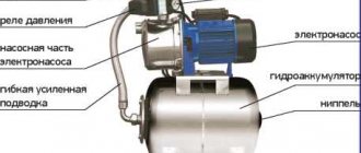
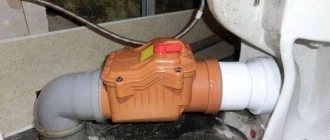
The design of a hydraulic accumulator with a replaceable membrane looks simple. This is a metal tank with an elastic membrane of a spherical or pear shape.
Purpose of the hydraulic accumulator
A hydraulic accumulator (in other words, a membrane tank, hydraulic tank) is used to maintain stable pressure in the water supply system, protects the water pump from premature wear due to frequent activation, and protects the water supply system from possible water hammer. When the power goes out, thanks to the hydraulic accumulator, you will always have a small supply of water.
Here are the main functions that a hydraulic accumulator performs in a water supply system:
- Protecting the pump from premature wear. Thanks to the water reserve in the membrane tank, when you open the water tap, the pump will only turn on if the water supply in the tank runs out. Any pump has a certain rate of starts per hour, therefore, thanks to the hydraulic accumulator, the pump will have a reserve of unused starts, which will increase its service life.
- Maintaining constant pressure in the water supply system, protecting against changes in water pressure. Due to pressure changes, when several taps are turned on at the same time, sharp fluctuations in water temperature occur, for example in the shower and in the kitchen. The hydraulic accumulator successfully copes with such unpleasant situations.
- Protection against water hammer, which can occur when the pump is turned on, and can seriously damage the pipeline.
- Maintaining a supply of water in the system, which allows you to use water even during a power outage, which happens quite often these days. This function is especially valuable in country houses.
Connecting the hydraulic accumulator
Before connecting the accumulator to the system, it is necessary to measure the pressure in it. This parameter is required to install the pressure sensor trigger relay.
At the factory, 1.5 Atm is set in the tank. To do this, you can use a car pressure gauge if there is no other one. To measure this parameter, there is a special entrance at the bottom of the hydraulic tank (from 100 liters).
- When using a surface type pump, install it near the hydraulic tank. The check valve is installed on the water supply pipeline.
- It is better to install all the devices necessary for the operation of the hydraulic accumulator using a five-pin fitting for piping in the circuit.
- The presence of leads with different diameters makes its use indispensable when installing a hydraulic accumulator in a water supply system.
Five-pin fitting
But this is an optional requirement.
Some people like to do things the old fashioned way, using fittings and pipe scraps.
Hydraulic accumulator device
The design of a standard hydraulic accumulator with a replaceable membrane (the most common type) is quite simple. Inside the accumulator there is an elastic membrane of a spherical or pear shape.
In operating mode, there is water inside the membrane, and between the walls of the tank and the membrane there is pre-injected air or other gas under pressure (the pre-injection value is indicated on the label). Thus, water does not come into contact with the walls of the accumulator, but only with the membrane, which is made of material suitable for contact with drinking water.
The membrane neck remains outside the accumulator housing and is securely attached to it by a steel removable flange using screws. Thus, the membrane is removable and can be replaced with a new one without much labor.
All hydraulic accumulators have a nipple in their design (like in a car wheel), which is directly connected to the air cavity of the tank. Through this nipple, you can regulate the air pressure inside the tank using a conventional air pump or compressor.
The nipple is located under a protective plastic cap, which can be easily unscrewed by hand.
It is important to note that many manufacturers have membranes in hydraulic accumulators with a volume of 100 liters and above attached not only from the bottom (via a flange), but also from the top. Through the hole in the upper part of the membrane (yes, in addition to the neck, the membrane will have another hole in the upper part) passes a special hollow rod, with a sealing element at one end and a thread at the other. The threaded end is brought out of the tank and is attracted to the latter by a nut. In fact, the part brought out is a threaded fitting. This threaded fitting can simply be plugged, or a pressure switch and/or pressure gauge can be installed on it.
In this case, the hydraulic accumulator (as well as the membrane to it) will be called pass-through.
Hydraulic accumulators come in vertical and horizontal versions. Vertical tanks are installed on legs, while horizontal tanks are mounted on feet and have a platform for installing additional equipment. Equipment (pump, control cabinet, etc.). The fundamental point for choosing a layout is the specific installation location.
When installed on the floor, a vertical tank will be more compact, but if the tank needs to be hung on the wall or there are height restrictions, choose a horizontal model.
Device
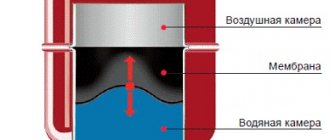
As we have already said, our device is divided into two parts by a pear. One of them collects liquid, the other collects compressed air. After filling the bulb, the water pressure will be balanced by air pressure, so the capsule liquid will not touch the metal walls of the tank. The membrane does not inflate to significant sizes through internal air pressure. A valve is installed on the body to regulate pressure.
Note! The supply pipes must be connected to the hydraulic accumulator in such a way that the device can be quickly disassembled for repairs without draining the water from the system.
In tanks with a volume of more than 100 liters, a special valve is provided, which serves to remove excess air released from the liquid. In smaller containers, a special tap is used for such purposes.
Principle of operation
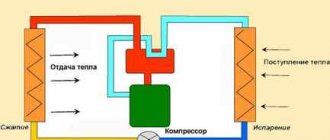
Radial membranes (in the form of a plate) are used mainly in gyroaccumulators for heating systems. For water supply, a rubber bulb is usually installed inside. How does such a system work? As long as there is only air inside, the pressure inside is standard - the one that was set at the factory (1.5 atm) or that you set yourself. The pump turns on, begins to pump water into the tank, and the pear begins to increase in size. Water gradually fills an increasingly larger volume, increasingly compressing the air that is located between the wall of the tank and the membrane. When a certain pressure is reached (usually for one-story houses it is 2.8 - 3 atm), the pump is turned off, and the pressure in the system stabilizes. When you open a tap or other water flow, it comes from the accumulator. It flows until the pressure in the tank drops below a certain level (usually about 1.6-1.8 atm). After which the pump turns on, the cycle repeats again.
The operating principle of a gyroaccumulator with a pear-shaped membrane
If the flow rate is large and constant - you are filling a bathtub, for example - the pump pumps water in transit, without pumping it into the tank. The tank begins to fill after all the taps are closed.
A water pressure switch is responsible for turning the pump on and off at a certain pressure. In most hydraulic accumulator piping schemes, this device is present - such a system operates in optimal mode. We’ll look at connecting the hydraulic accumulator a little lower, but for now let’s talk about the tank itself and its parameters.
Pressure switch for hydraulic accumulator and how to adjust
The device in question is used to automatically regulate the operation of the pump. When adjusting the pressure switch, you need to pay attention to the following terms:
- Lower pressure is the pump starting parameters, the standard value is 1.5 Bar;
- The upper pressure parameters are used to expand the relay contacts and further turn off the pump. The values used here are 2.5-3 bar;
- The maximum permissible pressure should not exceed 5 bar.
After starting the station, water begins to accumulate in the membrane or bulb. Subsequently, the liquid will be pushed through pipes to consumers. After purchasing the necessary equipment, you need to check the water pressure. The devices in question have special pressure gauges, but experts say that such devices have significant measurement errors.
Note! To check pressure readings, it is recommended to use a car pressure gauge with a special scale.
Pressure switch
When checking the air pressure in the membrane tank, remove the protective cover and connect the pressure gauge to the nipple. It should be noted that as the pressure in the hydraulic tank decreases, the volume of pumped liquid increases.
To create the required liquid pressure, air must be pumped into the container until the pressure reaches 1.5 atmospheres. An increase in indicators leads to frequent starts and wear of the pump. Too little pressure will cause the rubber bulb to swell and fail.
When adjusting the relay, you need to remove the cover from the device, after which we will find a housing with two springs on which a large and small nut is screwed. Note that the first nut regulates the lower pressure level (let's denote it with the symbol P). The second, small nut is used to adjust the pressure difference (usually designated by the letter H). Work begins relative to the lower pressure, which is set on a large spring.
Hydraulic tank with pressure switch
After filling the hydraulic tank with compressed air, turn on the pump and monitor the position of the pressure gauge needle. If the readings exceed the upper limit, you will need to turn off the pump. The maximum pressure in the system is set after the needle stops on the pressure gauge.
Note! When making adjustments, you must follow the recommended operating parameters of the pumping station specified in the product instructions.
When setting the relay, it is advisable to maintain the difference between the upper and lower pressure limits within one or two atmospheres, which will ensure proper use of the pumping station. After pumping water and setting the upper threshold, the pump is turned off and the relay begins to be adjusted. To do this, rotate the small nut until the mechanism starts. Next, drain the water from the system until the pump starts. This usually occurs at a lower pressure threshold.
Important! Set the lower limit 0.1-0.3 atmospheres higher than the pressure in the accumulator. This will increase the life of the pear.
At the next stage of work, rotate the large nut to set the lower pressure. Next, turn on the pump and monitor the pressure gauge needle; it should rise to the upper level. At this point, the work on regulating the pressure switch can be considered completed.
Types of hydraulic tanks
There are vertical and horizontal devices, they are installed in different ways. Typically, tanks with a capacity of up to 50 liters are placed horizontally, and larger ones - vertically, so as not to take up much space. This does not affect efficiency. You can choose a model that will be more convenient to use and suitable for the place where it will be installed.
The total volume of the hydraulic tank and the amount of water it can hold are different indicators. The container is selected depending on the characteristics of the plumbing system
In vertical and horizontal models, a nipple - an air valve - is provided to remove air from the part into which air or gas is pumped. It's very easy to use.
It is located on all types of hydraulic tanks on the side opposite to the installation of the flange intended for connecting equipment to the water supply.
Membrane tanks with a red body are intended for hot water supply systems or heating. They must be used strictly for their intended purpose.
The color of the container is usually blue or blue, in contrast to the red expansion tanks for heating. They are not interchangeable; different materials are used to make the membrane. Food-grade rubber is used in “cold” hydraulic tanks.
In addition, blue accumulators can withstand higher pressure than heating and hot water devices. You cannot use such containers for other purposes; they will quickly fail.
In vertically oriented HAs, water is supplied from below, and excess air is removed, if necessary, from above, bleeding it through the nipple. In horizontal versions, both water supply and air bleed are done from the side.
The threaded connection for connecting to the water supply is always the same size, it is 1 1/2 inches. The thread for connecting the membrane can be internal or external. Their dimensions are also unified, the internal thread is standard 1/2 inch, the external thread is 3/4 inch. This is an important point, since for a reliable connection it is necessary that the dimensions of the nozzle and the water pipe match.
If you plan to organize an independent water supply system, you need to know how a conventional water accumulator works. You should immediately decide on options for connecting to the water supply and methods for removing air if the pressure exceeds the standard value, as well as connection diagrams to the system.
Imported GA models look very presentable, but they are not always suitable for use in local conditions. Before purchasing such a device, you should read reviews
It should be remembered that they were initially designed to suit the conditions of the country where they were produced, and they do not always coincide with local realities. Operating conditions may be too difficult for Western models, so it makes sense to look for an option from a domestic manufacturer, which may be more attractive in cost.
The design and principle of operation of a hydraulic accumulator.
The Vodomaster.ru online store values the trust of its customers and takes care of keeping their personal data secret from scammers and third parties. The Privacy Policy is designed to ensure that personal information provided by users is protected from access by third parties.
The main purpose of collecting personal data is to ensure adequate protection of information about the User, incl. his personal data from unauthorized access and disclosure to third parties, improving the quality of service and the efficiency of interaction with the client.
BASIC CONCEPTS
Website – online store “Vodomaster.ru”, located on the Internet at the address: vodomaster.ru
User is an individual or legal entity who has posted his personal information through any Feedback Form on the site with the subsequent purpose of transferring data to the Site Administration.
Feedback form is a special form where the User places his personal information for the purpose of transferring data to the Site Administration.
User Account (Account) – a User account that allows you to identify (authorize) the User using a unique login and password. The login and password for accessing the Account are determined by the User independently during registration.
GENERAL PROVISIONS
2.1. This Policy regarding the processing of personal data (hereinafter referred to as the “Policy”) was prepared in accordance with clause 2, part 1, art. 18.1 of the Federal Law of the Russian Federation “On Personal Data” No. 152-FZ of July 27, 2006 (hereinafter referred to as the “Law”) and describes the methods of use and storage by the Vodomaster.ru online store of confidential information of users visiting the vodomaster.ru website.
2.2. By providing the online store "Vodomaster.ru" with private information through the Site, the User freely, of his own free will, consents to the transfer, use and disclosure of his personal data in accordance with the terms of this Privacy Policy.
2.3. This Privacy Policy applies only to private information obtained through the Site. Personal information is information that allows, when used separately or in combination with other information available to the online store, to identify the client’s personal data.
2.4. The site vodomaster.ru may contain links that allow you to go to other sites. The online store is not responsible for the information published on these sites and provides links to them only to ensure the convenience of users. However, this Policy does not apply to other sites. Users who follow links to other sites are encouraged to review the privacy policies posted on such sites.
CONDITIONS, PURPOSE OF COLLECTION AND PROCESSING OF USERS' PERSONAL DATA
3.1. Personal data of the User such as: first name, last name, patronymic, e-mail, telephone, delivery address, skype, etc., are transferred by the User to the Site Administration with the consent of the User.
3.2. The transfer of personal data by the User through any Feedback Form posted on the website, including through the order basket, means the User’s consent to the transfer of his personal data.
3.3. By providing his personal data, the User agrees to their processing (up to the User’s withdrawal of his consent to the processing of his personal data), in order for the online store to fulfill its obligations to the client, sell goods and provide services, provide reference information, as well as for promotion purposes goods, works and services, and also agrees to receive advertising and informational messages and service messages.
3.4. The main purposes of collecting information about the User are accepting, processing and delivering orders, providing feedback to the client, providing technical sales support, notifying about changes in the operation of the Site, providing, with the consent of the client, offers and information about promotions, arrivals of new products, advertising mailings; registration of the User on the Site (creation of an Account).
3.5. Registration of the User on the website vodomaster.ru is not mandatory and is carried out by the User on a voluntary basis.
3.6. The online store is not responsible for the information provided by the Client on the Site in a publicly accessible form.
PROCESSING, STORING AND PROTECTION OF PERSONAL INFORMATION OF SITE USERS
4.1. The Site Administration processes information about the User, incl. his personal data, such as: first name, last name, patronymic, e-mail, telephone, skype, etc., as well as additional information about the User provided by him at his own request: organization, city, position, etc.
4.2. The online store has the right to use “cookies” technology. Cookies do not contain confidential information and are not transferred to third parties.
4.3. The online store receives information about the IP address of the User of the site vodomaster.ru and information about the link from which Internet site he came from. This information is not used to identify the User.
4.4. When processing personal data of users, the online store adheres to the following principles:
- Information is processed lawfully and fairly;
- Information is not disclosed to third parties and is not distributed without the consent of the Data subject, except for cases requiring disclosure of information at the request of authorized government bodies or legal proceedings;
- Determination of specific legitimate purposes before processing (including collection) of information begins;
- Only the information that is necessary and sufficient for the stated purpose of processing is collected;
- The processing of information is limited to the achievement of specific, predetermined and legitimate purposes;
4.5. Personal information about the User is stored on the website’s electronic media indefinitely.
4.6. Personal information about the User is destroyed at the request of the User himself on the basis of his official request, or at the initiative of the Site administrator without explanation, by deleting information posted by the User.
4.7. The request for deletion of personal information sent by the User must contain the following information:
for an individual:
- number of the main identification document of the User or his representative;
- information about the date of issue of the specified document and the issuing authority;
- registration date via the Feedback Form;
- text of the appeal in free form;
- signature of the User or his representative.
for a legal entity:
- request in free form on company letterhead;
- date of registration via the Feedback Form;
- the request must be signed by an authorized person accompanied by documents confirming the person’s authority.
4.8. The online store undertakes to consider and send a response to the User’s request within 30 days from the date of receipt of the request.
4.9. The online store implements measures to protect personal data of Users in the following areas:
- preventing the leakage of information containing personal data through technical communication channels and other means;
- prevention of unauthorized access to information containing personal data, special influences on such information (data carriers) for the purpose of obtaining it, destroying it, distorting it and blocking access to it;
- protection against malware;
- detection of intrusions and computer attacks.
TRANSFER OF PERSONAL DATA
5.1. The Vodomaster.ru online store does not disclose personal information about Site Users to third parties, except in cases prescribed by Federal Law No. 152-FZ of July 27, 2006 “On Personal Data,” or when the client voluntarily agrees to the transfer information.
5.2. Conditions under which the Vodomaster.ru online store can provide private information from its databases to third parties:
- to satisfy demands, requests or court orders;
- for the purpose of cooperation with law enforcement, investigative or other government agencies. At the same time, the online store reserves the right to report to government authorities about any illegal activity without notifying the User about it;
- to prevent or investigate suspected wrongdoing, such as fraud or identity theft;
5.3. The online store has the right to use other companies and individuals to perform certain types of work, for example: delivering packages, mail and emails, removing duplicate information from customer lists, analyzing data, providing marketing services, processing credit card payments. These legal entities/individuals have access to users' personal information only when necessary to perform their functions. This information cannot be used by them for other purposes.
SECURITY OF BANK CARDS
6.1 When paying for orders in the Vodomaster.ru online store using credit cards, all transactions with them take place on the banks’ side in special secure modes. No confidential information about bank cards, except for notification of the payment made, is transmitted to the online store and cannot be transmitted.
CHANGES AND ADDITIONS
7.1. Any changes to the terms or conditions of the Personal Information Policy will be reflected in this document. The Vodomaster.ru online store reserves the right to make changes to certain sections of this document at any time without prior notice by posting an updated version of this Privacy Policy on the Site.
Criteria for selecting a suitable hydraulic tank
When choosing a specific hydraulic accumulator, you must be guided by the following criteria:
- Number of consumers
- Working fluid temperature
- Cost of equipment
- When using a hydraulic tank to compensate for changes in coolant pressure in a closed heating system, volumes from 6 to 25 liters are sufficient (the specific figure depends on the size of the heating system itself). The remaining characteristics of the hydraulic tank allow it to confidently work in the same system with heating devices (for example, the maximum pressure that the boiler heat exchanger can withstand is 2-5 atmospheres, and for the hydraulic tank - 9-12 atm)
Hydraulic accumulator and expansion tank - what is the difference
Expansion tank
In appearance, the two containers under consideration are similar to each other. An expansion tank is used in a heating system; its main purpose is to compensate for excess pressure that occurs as a result of expansion of the heated liquid. During operation of the boiler, the temperature of the coolant rises, which leads to its expansion and increase in volume.
According to experts, heating water by just 10 degrees increases its volume by 0.3%. That is, a 50 degree difference in the coolant temperature readings before and after heating will increase its volume by 1.5%. Liquid doesn't compress; it has to go somewhere. This is what an expansion tank is used for.
The hydraulic accumulator is considered one of the main devices of the plumbing system. The main tasks of this device are to accumulate water in the system and maintain the required pressure. The presence of an additional reservoir allows you to reduce the number of starts of the pumping station, which will contribute to the long-term operation of the power plant.
The next important function of the membrane tank is to protect the water supply from water hammer. As you know, water hammer most often occurs when a pumping station is started or shut down, as well as when taps are suddenly turned off. A rubber bulb or membrane in a container allows you to balance the excess pressure that occurs in the system.
Vertical accumulator
Despite the fact that the expansion tank and the hydraulic accumulator are similar to each other, there are differences between them, and significant ones. The design of the hydraulic accumulator has a special membrane or bulb, which is used to compensate for pressure. The expansion tank also has a special partition that divides the container into two parts: the first is filled with water, the second with air. If oxygen and liquid come into contact in the heating expansion tank, then in the hydraulic accumulator the contact of these two substances is unacceptable.
Calculation of the optimal volume of the hydraulic tank
A correctly selected hydraulic tank volume will allow:
- ensure sufficient water consumption,
- optimal use of pumping equipment,
- extend the service life of the drive and system elements.
There are several ways to select a hydraulic accumulator for water supply systems and calculate the required storage volume.
Italian engineers have developed a calculation method UNI 8192. Selection is carried out according to three parameters: maximum water flow, the number of permissible pump starts per hour and the water supply height.
If the need for water supply is small, for example, for a family of 2-3 people living in a one-story house, the volume of the hydraulic tank can not be calculated. A 24-liter container will be enough.
For houses with more floors and with a considerable number of water consumption points, a calculation should be made.
The required hydraulic tank size can be selected only based on calculations
It is carried out according to the scheme:
- The tables determine the total coefficients of water consumption depending on the equipment used.
- The maximum water flow is calculated. For example, when a shower, cistern and faucet work together in the kitchen, this figure will be 30 l/min (Qmax).
- The estimated number of pump starts per hour (for comfortable operation) is taken as a=15. With more intensive work, the hydraulic tank membrane oscillates too frequently, which leads to its premature destruction. In addition, the pump’s performance does not make it possible to completely fill the reservoir with water. During continuous operation, the pump overheats and fails faster.
- The next important value is the maximum and minimum pressure for the relay to operate. For two-story houses these values are 3 bar and 1.5 bar, respectively (Pmax and Pmin). The initial gas pressure in the setting P0=1.3 bar is included in the calculation.
- The required volume is determined by the formula: V=16.5 x Qmax x Pmax x Pmin /(ax (Pmax-Pmin)x P0)=16.5x30x3x1.5/(15x(3-1.5)x1.3)=76 l.
The closest in value is a tank with a volume of 80 liters.
A hydraulic accumulator for water supply systems with such a capacity will allow meeting the water supply needs of residents of a 2-story building with three water collection points operating simultaneously.
How to correctly calculate and select a hydraulic accumulator can be seen in the video:
Do you need extra capacity?
The additional volume of water stored in the hydraulic tank does not affect its operation. The main function of the unit is to maintain pressure in the water supply network.
If a significant supply of water is needed, it is easier and much cheaper to integrate a plastic reserve tank into the system. Therefore, when selecting equipment, it makes no sense to purchase a hydraulic accumulator with a reserve.
If the need for water supply increases, for example, with an increase in the number of residents or the number of household appliances consuming water, you can additionally install another small-volume hydraulic tank. Their performance is cumulative. The installation location of the additional hydraulic tank does not play an important role.
If necessary, several hydraulic tanks can be installed in the system
How to choose a hydraulic accumulator
First of all, you need to decide for which system you plan to use the hydraulic accumulator.
- For a device that will monitor the supply of cold water, it is necessary to proceed from the number of people living in the house and, according to the consumption rates of cold and drinking water per person, purchase a suitable hydraulic accumulator.
- The unit that supplies hot water is also purchased after calculating the hot water consumption per person per day.
- The hydraulic accumulator, which ensures uninterrupted operation of the heating system, is selected based on the area of the heated premises. Depending on this, the capacity of the hydraulic tank is selected.
It is also necessary to take into account that the operation of the entire unit is based on the use of a membrane container, which is located inside the hydraulic tank.
Selecting a hydraulic accumulator
The service life of the entire system depends on its survivability. For cold water, it is better to purchase a tank with a membrane made of isobutated rubber, the water from which is safe for use in cooking.
Next, when making a choice, you need to pay attention to the flange that secures the water supply system. Its quality affects the life of the hydraulic accumulator.
Accumulator flange
The better the quality of the flange, the longer the accumulator will work. Made from galvanized steel, stainless steel or composite plastic.
Calculation of the optimal volume of the hydraulic tank
There is no GOST standard for the volume of a hydraulic tank. Everyone chooses a container for using water individually. You need to start from two parameters.
Hydraulic tank dimensions
- The size of the utility room where at least one hydraulic tank will be installed. For example, the size of a 100 liter tank is a barrel standing vertically, about 850 mm high, and 450 mm in diameter.
- Next, you need to calculate the amount of water consumed by each family member (approximately). Also, take into account the water consumption when doing laundry, washing dishes and other household needs. In any case, even if an error was made in the calculations, you can always replace the tank and increase its capacity.
A few words about the connection diagram
Membrane accumulators are installed between the pump and the internal water supply. Since there is only one hole in the container, a crosspiece is used for connection, to which three elements are in turn connected:
- Pressure switch through which the pump is connected to electricity;
- The pump itself;
- A water pipe connecting the storage tank to the internal water supply.
The maximum pressure in the system should be 2.5-3 bar; when it is reached, the pump should turn off. The minimum is usually 1.5-1.8 bar.
Therefore, installing the container is not difficult even for beginners. The main thing is to ensure the tightness of all connections.
In addition, you need to configure the relay by setting the minimum and maximum pressure. Detailed information about this procedure is contained in the operating instructions for the device.
Features of installation of a hydraulic accumulator
When purchasing a specific model of hydraulic accumulator, you need to take into account a number of features of its installation:
- Always installed after the injection pump
- A pressure switch is mounted next to it (its sensors collect information about the state of the liquid before the pump, after it, in the hydraulic pump and in, in fact, the in-house water supply system itself, it also gives the command to turn on the pump)
- Needs a solid foundation
- Under the support platform or legs of the hydraulic accumulator, you should always place a shock-absorbing pad made of foam rubber 1.5-2 cm
Taking into account all these requirements allows you to evaluate in advance the possibility of reliable placement of the hydraulic tank in the selected location. Most often these are utility rooms for heating boilers or water treatment systems and pumps.
Malfunctions
Most often, hydraulic accumulators fail for the following reasons:
- too frequent starting/shutdown of the pump;
- valve leakage;
- water pressure at inlet/outlet is too low.
Before identifying the reason behind the weakening of pressure, it is necessary to determine what exact pressure should be in the station’s hydraulic tank.
In this case, problems may be as follows:
- incorrect pressure;
- damage or deformation of the membrane part or housing;
- relay failure.
You can deal with the difficulties that have arisen in the following ways:
- Injection of pressure in case of its decline;
- restoration of damaged membrane;
- restoration of damaged hull;
- differential adjustment based on pump mode.
Types of hydraulic accumulators
These devices can be in vertical or horizontal configurations.
The operating principle of the devices is no different, except that vertical hydraulic accumulators with a volume of more than 50 liters have a special valve in the upper part for bleeding air, which gradually accumulates in the water supply system during operation. Air accumulates in the upper part of the device, therefore the location of the valve for bleeding is chosen in the upper part.
In horizontal devices for bleeding air, a special tap or drain is mounted, which is installed behind the hydraulic accumulator.
From small devices, regardless of whether they are vertical or horizontal, air is released by completely draining the water.
When choosing the shape of a hydraulic tank, proceed from the size of the technical room where they will be installed. It all depends on the dimensions of the device: whichever fits best into the space allocated for it will be installed, regardless of whether it is horizontal or vertical.
Hydraulic accumulator calculation
To determine how much water can be used from the accumulator when the power is turned off, when the pump stops pumping water from the water supply system, you can use the membrane tank fillability table. The water supply will depend on the setting of the pressure switch. The higher the pressure difference when turning the pump on and off, the greater the supply of water in the accumulator. But this difference is limited for the reasons stated above. Let's look at the table.
Here we see that in a membrane tank with a volume of 200 liters, with the settings of the pressure switch, when the indicator on the pump is 1.5 bar, the pump off is 3.0 bar, the air pressure is 1.3 bar, the water supply will be only 69 liters, which is equal to approximately a third of the total volume of the tank .
Calculation of the required volume of the hydraulic accumulator
To calculate the accumulator, use the following formula:
Vt = K * A max * ((Pmax+1) * (Pmin +1)) / (Pmax- Pmin) * (Pair + 1),
Where
- Amax – maximum flow rate of liters of water per minute;
- K is a coefficient that depends on the power of the pump motor;
- Pmax – pressure when the pump is turned off, bar;
- Pmin – pressure when the pump is turned on, bar;
- Pair – air pressure in the hydraulic accumulator, bar.
As an example, let’s select the required minimum volume of a hydraulic accumulator for a water supply system, taking, for example, the Aquarius BTsPE 0.5-40 U pump with the following parameters:
| Pmax (bar) | Pmin (bar) | Pair (bar) | A max (cubic m/hour) | K (coefficient) |
| 3.0 | 1.8 | 1.6 | 2.1 | 0.25 |
Using the formula, we calculate the minimum volume of HA, which is 31.41 liters.
Therefore, we choose the next closest GA size, which is 35 liters.
The tank volume in the range of 25-50 liters is ideally consistent with all methods for calculating the volume of hydraulic fluid for household plumbing systems, as well as with the empirical assignments of different manufacturers of pumping equipment.
If there are frequent power outages, it is advisable to choose a tank of a larger volume, but at the same time you should remember that water can only fill the tank by 1/3 of the total volume. The more powerful the pump installed in the system, the larger the volume of the accumulator should be. This sizing will reduce the number of short starts of the pump and extend the life of its electric motor.
If you bought a large-volume hydraulic accumulator, you need to know that if water is not used regularly, it will stagnate in the hydraulic accumulator and its quality will deteriorate. Therefore, when choosing a hydraulic tank in a store, you need to take into account the maximum volume of water used in the home’s water supply system. After all, with a small water consumption, using a tank with a volume of 25-50 liters is much more expedient than 100-200 liters, the water in which will be wasted.
Choosing a location for a water supply station
This choice largely depends on the parameters of the hydraulic pump. Every ten meters it passes through a horizontal pipe, its suction characteristics decrease. For example, for pumping water from a depth of more than 10 meters, only certain pump models may be suitable.
An automatic water supply station should be installed in the following places:
- in a caisson, next to the well;
- in a separate pavilion for pumps;
- in the basement.
If you chose an external stationary pump, lay a pressure pipe from the caisson to the cottage. Moreover, the pipe must lie below the frozen soil. This really makes sense if the pipeline is used all year round. If you need to lay pipes only for the summer, a depth of 40-60 cm will be quite enough, or the laying can be done completely on the surface.
If you are planning to install the station on the ground floor or even in the basement, you don’t have to worry that the pump may freeze in the winter cold. It is necessary to lay the pipe below the frost line of the soil, and the problem will be solved.
Drilling a well can also be done right at home to reduce the length of the pipeline. The only question is about the possibility of such a step in various private houses and cottages.
If you want to install the station in a special separate extension, keep in mind that this is only suitable for warm seasons. Otherwise, a separate heating system will have to be installed in this extension, and it is better to immediately install the equipment in the heated house.
Advantages of a pumping unit equipped with a hydraulic tank
A pump is an almost necessary component for a water supply system, used to transport water to your cottage from a well or borehole. Then, directly in the house itself, water is distributed through a tank or accumulator. Or again, using the pump itself.
When using only one pump to transport and distribute water around the house, you risk being left without water completely if there is no electricity at the moment. In addition, in this situation, the pump will constantly turn on and off, which will lead to a sharp reduction in its service life.
Pumping station with hydraulic tank
To reduce the load on the pump, and also make your home safer in the event of a power failure, add another storage tank to your system that supplies water to your country cottage. The first option is a gravity-fed water tank or a hydraulic accumulator that maintains water pressure in the network. Another name for a hydraulic accumulator is a hydraulic tank.
The option with a hydraulic tank is the most comfortable and common. In such a system, the pressure force in the pipes is maintained, and the pump is turned on only when the container needs to be filled with water. Water is supplied using compressed air.