Water pressure switch for a pump: operating principle, correct adjustment, step-by-step installation instructions, advantages and disadvantages, selection tips.
If suburban properties do not have a centralized water supply, you cannot do without equipping an autonomous system for supplying liquid from a well or well. In this case, a necessary part of the design is the pump. The operating mode of this device determines a lot. In turn, the functionality of the water pumping station depends on the water pressure switch for the pump, which is responsible for controlling its operation.
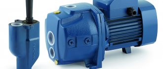
Water pressure switch for pump
What it is?
Water pressure relay (detector) is a device that, depending on the water pressure, starts or stops the pump.
The relay is a compact device weighing less than 0.5 kg , enclosed in a plastic case.
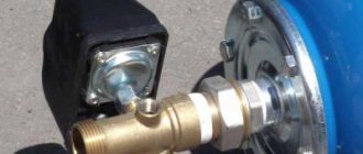
It is connected to the water supply system by a pipe with a union nut.
Two cables are supplied to the device through couplings in the housing. One connects the device to the pump, the second to the electrical network. Used to stabilize the operation of a water supply system or pumping station.
Design and principle of operation
The device includes 4 main structural elements:
- Sensitive element.
- Regulators that set the lower and upper levels of operation of the device.
- A unit (mechanical or electronic) that compares the actual pressure with the specified one.
- Switching elements that control the pump.
The actions of the device can be described by a simplified algorithm. When the pressure is low, the relay supplies voltage to the motor. The pump is running and water is being pumped into the pipes.
When it is high, on the contrary, the device de-energizes the engine. The pump stops and stops pumping water. As a result, the pressure in the pipes always remains within an acceptable range (most often from 1.2 to 2.4 bar).
The relay starts the pump only when necessary and maintains an acceptable level of water pressure. This extends the life of the pump, other devices and units.
How does a mechanical pump station water pressure controller function?
Knowing its design will help you better understand how to set up and how the control unit works. In the first picture below, the contacts are disengaged, the rocker frame is in the lower position, lowered. A large spring regulates the starting torque - this is the minimum number of MPa in the equipment. The small spiral sets the upper threshold, or more precisely, the difference ΔР between Pmin and Pmax.
Let us describe the lower mark of the pressure range (Pmin). We will remove the small spring (Fig. 2) - it will not be needed for explanations. So the circuit is open. Through the lower fitting and nut, communicating with the circuit, pressure is transmitted to the membrane compartment. Pyatak moves the movable platform with its protrusions, it rises. To throw the rocker up to close the contacts, you need to lower the plate to the level of the spring actuation; a certain force from above is required, and it is created by a large spiral if you compress it while tightening the stud nut (Fig. 3).
The nut goes down - the spring compresses, the pressure on the platform increases, at a certain moment it is equalized, then exceeds the force of influence coming from below through the nickel. The plate begins to lower - the rocker throws up, closes the contacts - power is supplied to the pump.
The position of the nut for starting is easy to determine by checking the actions with a pressure gauge, the method of connecting it, which is elementary, is to the outlet for this device on the main fitting of the assembly (the electric propulsion engine and some mechanical models have this unit in their composition). This is what adjusting the lower pressure limit consists of.
Note that when the controller is removed, or when there is no pressure in the circuit at all, the contacts are interlocked (Fig. 3) and this is understandable: the spiral presses from above, and there is no resistance from below. Therefore, the relay is called normally closed; if the power is connected after assembling the circuit, the pump will start.
The operating principle is as follows. The pump is started, fills the HA, the number of mPa increases, the pressure of the piston from below on the platform also increases. When it exceeds the force of the large spring, it will begin to go up; at a certain point, this movement will end with the rocker being thrown down. The contacts will separate, the relay will open the contacts, and the pump will turn off. In our case, the parameters of the large spiral are such that to overcome its influence a difference of about 0.5 atm will be required, which is not enough (the normal range width is 1.5 atm). It is logical that to increase the resistance of the plate to lifting under the influence of the piston, some kind of pressure from above is necessary. This is precisely what a small adjustable rod with a spiral will provide, allowing you to accurately set the difference between the upper and lower pressure limits (the same 1.5 atm.).
The cycle with a fully configured pressure switch for a pumping station looks like this:
- The pump is activated, the HA is filled, and the MPa number increases.
- The platform goes up and rests on the small spiral adjusting washer.
- At a certain point, when the pressure exceeds the minimum limit, in our example by 0.5 atm, the plate suppresses the force of the large regulator and begins to move upward. But the relay does not reach the tripping mark; it is stopped by the lower washer of the small spiral. Now, for further upward movement, additional pressure will be required, and it will be higher, the stronger the compression of the small adjusting screw. This sets the difference between the lower and upper limit of activation of the release (Fig. 3 below). That is, only when the piston force is higher than that from the small adjusting screw will the platform continue its upward path and reach the taxiway switching mark.
- The pressure increases when the pump is activated, reaching the point where the force of the coin overcomes the total resistance of the two springs. The plate rises, reaches a point at which the rocker lowers and opens the contacts, the pump turns off. The adjusted pressure switch and equipment can remain in this state for a long time - until the water supply is consumed or until consumption causes a decrease in MPa to the minimum threshold (4 Fig.).
- When liquid is consumed, the number of mPa drops, as does the force of the piston from below on the platform, while the large spiral begins to move it down. At the lower pressure threshold, the plate should come to a point where the spring throws the rocker up to close the contacts. The pump starts and the cycle repeats. That is, with the correct settings, a pressure drop even lower is impossible.
Let us remind you that a large spring sets the maximum pressure, a smaller one sets the range between the upper (off) and lower (on) points. To set the activation/deactivation of the relay at a higher value of mPa, the nuts are tightened, and loosening leads to a decrease in the values.
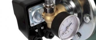
The water pressure sensor in the water supply system looks like a small box, mounted on the outlet (to consumers) pipe of the pump, in front of the expansion tank.
Types of pump devices
Mechanical, pointer and electronic versions of pressure detectors are available.
The main task for all types of devices is the same: depending on the water pressure, start or stop the pump.
All types of devices are mounted using union nuts or fittings with internal, less often, external threads. The thread size is 1/4″ or 3/8″ or 1/2″.
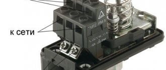
Electrical cables are led through couplings into the body of the device, where they are connected to screw terminals. Otherwise, the designs of relay types differ radically.
Pointer and electronic devices have wider functionality than mechanical ones. Therefore, it is better to consider in detail the operating principle and device separately for each type.
Mechanical
The simplest relays are mechanical. Sometimes they are called electromechanical. Both names can be considered fair.
Water enters the inlet chamber, which is closed on one side by a membrane (diaphragm), most often rubber. A membrane is a sensitive element of a mechanical device.
Under the pressure of water, the elastic rubber plate bends and lifts the brass plate. On the other hand, a spring presses on this plate. With high water pressure, the diaphragm overcomes the spring force.
The movement of the plate causes the switch to operate. The pump is de-energized and stops working.
Over time, water pressure drops. The spring overcomes the deflection of the membrane. The switch closes the contacts.
Voltage is supplied to the motor. The pump is running. The water pressure increases until the relay turns off the power to the pump again.
The moments at which the detector is triggered can be changed. The screw that tightens the main spring allows you to increase or decrease the pressure at which the pump turns off.
In the relay mechanism, in addition to the main one, there is an auxiliary spring. By tightening or loosening it, the point at which the pump turns on changes. This changes the operating range of the device.
The mechanical relay does not turn off the pump in the absence of water, that is, it does not protect it from dry running. Therefore, an idle (dry) running protection device is mounted next to the mechanical relay.
Switches
Detectors of this type can be classified as electromechanical. Structurally, they are improved dial pressure gauges.
The sensitive element of the device is a Bourdon tube (spring). When the water pressure increases, the tube unfolds; when it decreases, it collapses. The arrow of the device is connected to the tube, its movement corresponds to a change in pressure.
Under the dial glass, the device has 2 indicators (marks, flag). The first corresponds to the pressure at which the pump starts to operate. The second corresponds to the pump shutdown point. In fact, these are contacts associated with the controller that turns the pump motor on/off.
The position of the pointers is changed using two regulators. Each adjuster has a slot for a flathead screwdriver.
By rotating the knob, you can move the pointer associated with it.
The pressure value at which the pump turns off (the maximum pressure in the system) is usually set to 2.8 bar. The pressure at which water injection stops is 1.4 bar.
After the start, the water pressure in the system gradually increases. The arrow of the device reaches the flag that marks the limit numbers. The pressure should not rise higher. The controller reacts and turns off the pump motor.
Users waste water and the pressure in the system decreases. The pressure gauge needle drops. When the arrow reaches the minimum pressure indicator, a signal appears at the controller input indicating: it’s time to turn on the pump.
The algorithm of actions of a pointer and mechanical relay is similar, but the implementation is fundamentally different. In addition, the controller built into the pointer device expands its capabilities.
All models of pointer detectors not only perform pressure maintenance functions, but also stop the pump if there is no water.
Restarting the pump using a relay is possible using a button installed on the device body. More “smart” devices turn on themselves after some time.
Electronic
Water presses on the measuring pad of the sensor.
The electrical resistance of the strain gauge (sensor) changes. The built-in controller reacts to the change.
First of all, it converts the analog signal coming from the sensor into a digital one. The measured pressure is digitally displayed on seven-segment indicators.
The pressure value is not only indicated, it serves as the basis for making a decision to turn on or stop the pump.
Functions of electronic devices:
- measuring water pressure, depending on its value, turning the pump on/off;
- protection against idle (dry) running;
- starting a stopped pump after a pause;
- protection against frequent switching on.
For mechanical pressure detectors, the sensitive element is a membrane, for pointer ones - a Bourdon tube, for electronic ones - a strain gauge. Most often this is a semiconductor strain gauge.
Find a detailed review of electronic relays here.
Which one is better to choose?
Mechanical devices are simple, reliable and cheap. They are used in structures for irrigation or filling a pool. Systems with large volume hydraulic accumulators can also work with this device.
Do not forget that the use of this type of device may require the installation of a pressure gauge and a device that protects the pump from idling.
A pointer relay is a reliable device. It is convenient to read readings from it. It is easily adjustable. The response accuracy of a pointer detector is higher than that of a mechanical one. Switch devices are used to create water pipelines in country houses and apartments.
An electronic relay is superior in accuracy to mechanical and pointer ones. Manufacturers claim the high reliability of this device.
Relay settings
The manufacturer ensures that pumping stations are set to average values:
- lower level – 1.5-1.8 bar;
- upper level – 2.4-3 bar.
Lower pressure threshold
If the consumer is not satisfied with these values, then knowing how to adjust the pressure in the pumping station, they can be changed. Having figured out how to set the correct pressure in the storage tank, we begin to adjust the sensor settings:
- The pump and relay are disconnected from power. All fluid is drained from the system. The pressure gauge is at zero at this moment.
- The plastic cover of the sensor is removed using a screwdriver.
- Turn on the pump and record the pressure gauge readings at the time the equipment is turned off. This indicator is the upper pressure of the system.
- The tap furthest from the unit opens. The water gradually drains and the pump turns on again. At this moment, the lower pressure is determined by the pressure gauge. The pressure difference to which the equipment is currently set is calculated mathematically - by subtracting the results obtained.
Attention. To obtain the correct setting, you need a reliable pressure gauge whose readings you can trust.
Having the opportunity to estimate the pressure from the tap, select the required setting. Adjustment to increase the pressure of the pumping station is carried out by tightening the nut on a large spring. If the pressure needs to be reduced, the nut is loosened. Do not forget that adjustment work is carried out after disconnecting the device from the power supply.
Attention. The setting is carried out carefully; the relay is a sensitive device. One turn of the nut changes the pressure by 0.6-0.8 atmospheres.
Upper pressure threshold
To set the optimal frequency of pump activation, it is necessary to adjust the pressure difference. A small spring is responsible for this parameter. The optimal value of the difference between the upper and lower pressure thresholds is 1.4 atm. If it is necessary to increase the upper limit at which the unit turns off, then turn the nut on the small spring clockwise. When decreasing - in the opposite direction.
Setting scheme
What effect does this adjustment have on the equipment? A reading below average (1.4 atm) will ensure a uniform supply of water, but the unit will turn on frequently and quickly break down. Exceeding the optimal value promotes gentle use of the pump, but the water supply will suffer due to noticeable pressure surges. The pressure difference of the pumping station is adjusted smoothly and carefully. The result of the impact requires verification. The scheme of actions performed when setting the lower pressure level is repeated:
- All devices are disconnected from the electrical network.
- Water is drained from the system.
- The pumping equipment is turned on and the result of the adjustment is evaluated. If the performance is unsatisfactory, the procedure is repeated.
There are limitations to consider when making differential pressure settings:
- Relay parameters. You cannot set the upper pressure threshold equal to 80% of the maximum value of the device. Data on the pressure for which the controller is designed are present in the documents. Household models usually withstand up to 5 atm. If it is necessary to increase the pressure in the system above this level, it is worth buying a more powerful relay.
- Pump characteristics. Before choosing an adjustment, you must check the equipment specifications. The unit should turn off at a pressure of 0.2 atm. below its upper limit. In this case, it will function without overload.
Advantages and disadvantages
Advantages:
Thanks to the ability to maintain an acceptable pressure, the use of water becomes more comfortable, washing machines and dishwashers operate smoothly.- The relay reduces pump wear.
- Allows you to avoid accidents and flooding associated with burst pipes.
- Many device models do not allow the pump to run dry.
- Pointer and electronic types of relays perform the functions of pressure gauges.
But there are also disadvantages. The relay maintains water pressure in a fairly wide range, for example, from 1.2 to 2.8 bar. Such a spread may not always suit the user.
Installing a pressure stabilizer can rid the system of this shortcoming. In water pipelines where, in addition to the relay, a stabilizer is installed, the pressure is maintained accurate to tenths of a bar (atmosphere).
When using the detector, the pump is turned on and off, with an interval from 5 minutes to several hours.
Each switching on is a large or small pressure surge, that is, a water hammer. This jump is partially compensated by the hydraulic accumulator. A special device that ensures a smooth start of the pump helps to completely get out of the situation.
Hydraulic accumulator
The reserve in the hydraulic accumulator (also known as a membrane expansion tank) is enough for washing and some other small needs (drinking, cooking small amounts of food), without the need to turn on the supercharger.
GA is a sealed metal container (cylinder) inside with a rubber membrane or bulb that divides the vessel into 2 parts: one with compressed air, the second for water. The first creates pressure in the container, it compresses the ball of liquid, pushing it into the water supply. And when the rubber part is filled with water, the air is compressed, increasing its pressure on the bulb for subsequent extrusion.
With gradual flow, the pressure inside the HA decreases until it reaches the pump start threshold. Then, after consumption, the tank is filled, accordingly, the number of mPa gradually increases - the pump shutdown value is reached. The process ensures an even, stable pressure, no matter what surges there are at the entrance to the tank.
The role of the accumulator
Pressure regulation is closely related to the HA (on average its volume is 20...100 l), the relay will work without it, but the circuit will only be complete with it.
What is the importance of the device:
- it is the membrane tank that creates the required pressure, the adjustment frames required for effective operation, a wide range of on/off threshold values;
- provides an even pressure, eliminates water hammer, one of the most destructive phenomena for pipes and all equipment;
- creates a reserve required when smoothing out pressure and in case of overconsumption.
The purpose and task of connecting the pressure switch to the pump is to alternate the switching on of it and the hydraulic tank. The main function of the device, like all relays, is the engagement/disengagement of electric drive contacts when user-set threshold values, in our case pressure, are reached.
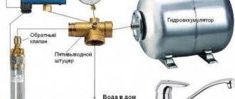
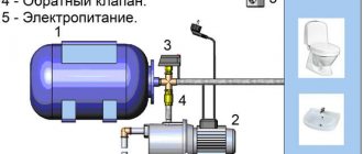
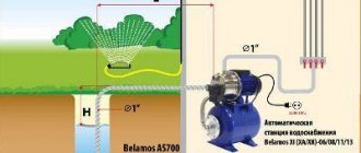
Place of the expansion tank in a circuit with a deep pump:
Location of the hydraulic accumulator in the circuit with the pumping station:
Hydraulic tank calculation
Calculating volume and pressure for a hydraulic accumulator (expansion tank) is a separate topic, so we will only indicate the basics.
Sometimes they make the mistake of thinking that the larger the volume, the greater the reserve, the pump turns on less often and this is better, but this is only partly true for the following reasons:
- loads increase, HA fails faster, and the cost of repairs and replacement of the membrane of larger devices is much higher;
- big difference between min. and max. pressure will lead to a decrease in comfort, for example, a shower is taken at 3.5 atm., which will decrease in the process to 1.5 atm. This reduction in pressure is noticeable, which can make the user nervous;
- Not all plumbing equipment likes high pressure; the risk of leaks increases;
- too large a reserve is fraught with stagnation in the tank.
The task of redundancy for hydraulic pumps is secondary; the main goal is to smooth out water hammer and reduce the number of pump starts. And for increased reserves, separate storage tanks are installed.
We must remember the following nuance and make a selection taking it into account: the water in the expansion vessel occupies on average about 1/3 of the total volume of the tank, the space for the liquid changes with the change in pressure in the vessel, as can be seen in the tables we provide.
Before adjusting the water pressure switch, you must also remember that the optimal difference between the start/stop points ΔP is 1.5–1.8 atm. Some relays do not even provide for adjustment of this value - they are initially assembled precisely for the specified number. The average statistical minimum in a pipeline for water supply to a private house is 1.5–1.8 atm, the maximum is 3 atm, while, as we indicated above, the water supply in the water supply system is 1/3 of its total volume. This ratio is clearly visible in the table.
Inside the reserve tank, the value should be 0.1–0.5 bar less than for turning on the pump (relay threshold for starting). Example: for a pump with a minimum for activating automation of 1.6 bar, the normal value in GA is 1.3–1.5 bar. This is the lowest value for air pressure. Manufacturers also prescribe the maximum possible value in the instructions; it varies for different models, as a rule, from 5 to 10 bar.
It is highly advisable to configure and connect the relay taking into account the on/off frequency. pump per hour specified in its technical documentation. There is a general recommendation: if the system is continuously operating at maximum flow, it is advisable that the device is started no more than once every 4–5 minutes, that is, 12–15 times/1 hour.
For precise calculations, there are many calculators on the Internet, as well as formulas, but this is a separate topic, here we will indicate the average norms for selecting GAs:
- based on the number of water points: 1–2 - volume from 20 to 50 l;
- 3–4 - 80...100 l;
- 4–5 - 150...200 l;
- 0.5 kW - 24 l;
When is a device necessary and is it possible to do without it?
Pressure detectors are installed in all permanently operating autonomous water supply systems.
Rural houses and country buildings are not the only places where these devices can be installed.
In central water supply complexes and multi-storey buildings, cases of low water pressure are common.
For example, on the upper floors. To correct the situation, additional pumping equipment is installed. In these cases, you cannot do without pressure detectors.
The simplest designs do not install devices that control water pressure. Usually these are seasonal water supply systems with large-capacity storage tanks. Timely shutdown of the pump in such systems is carried out manually or using a float sensor.
Auxiliary water pipelines designed for irrigation, filling a swimming pool or supplying water to bath and shower containers also do not require the installation of pressure detectors.
Popular relay models
Among the numerous components of water supply systems that are present on the Russian market, main categories can be distinguished. Expensive models have an upper limit of 4-8 atm. Most experts advise purchasing options such as:
Their limit is standard - 8 and 4 atm. The main advantage of such an acquisition will be the ability to self-adjust. It should be noted that both models belong to the category of low-current products, so it is not advisable to connect the units to a 220 V network. For ease of use, it is recommended to use a special control panel. Also, not every family can afford such a purchase.
Often, the buyer chooses a cheap and affordable unit. For example, a 4-atm device will cost 4,000 rubles, while its 8-atm counterpart costs 6,000 rubles.
Inexpensive models also have a limit of 5-8 atm. An example is the MDR 5-8 and MDR 5-5 designs. Their upper limit indicator is 8 and 5 atm, respectively. The first purchase will cost 2.9 thousand rubles, while the second will cost 2.1 thousand rubles. Installation of both devices is carried out on a membrane tank. It is possible to connect to a network of 220 V, as well as with an indicator of 380 V. For the first case, you will need a single-phase pump. Otherwise, you will need to purchase a three-phase model. Their current ratings are high. They are also characterized by an excellent degree of reliability.
Budget designs. These include PM-5 from the Italian concern. He copes with the assigned tasks 100%. It is worth noting that the average price for a similar product is several times less than that stated by Grundfos. The price of the device is 400 rubles. Works great in combination with household pumping units. Among the positive characteristics, you need to pay attention to the quality indicator and the ability to work with a 220 V network. However, during the connection process you may encounter some difficulties. It is not possible to connect to a 320 V network.
Relay, reducer, pressure stabilizer - what and when to choose?
In addition to the relay, the responsibility for maintaining water pressure rests on 2 more devices: a reducer and a pressure stabilizer.
A reducer is a valve with a spring as an actuator. Designed to maintain pressure in the water supply.
The operating principle is simple. When the pressure in the supply pipes is low, the spring opens the valve completely.
At high pressure, the spring partially closes the valve, causing a drop in pressure in the pipes behind the valve.
A pressure stabilizer is a device with a pressure sensor and an electric drive that closes and opens the valve. Designed to accurately maintain pressure in the water supply system.
The reducer and stabilizer cannot increase the water pressure. They maintain a given outlet pressure if it is high enough at their inlet. Stabilizers do this with high precision, gearboxes are rougher.
The reducer and stabilizer cannot replace the pressure switch. But installing them will be beneficial. Mount the gearbox and stabilizer between the hydraulic accumulator and the water collection point.
Selection criteria
The specific model of the device is selected based on design features, the authority of the manufacturer and the technical parameters of the device.
By design
For installation, relays of all types are provided with union nuts or fittings with internal threads, less often with external threads.
Union nuts are more convenient for installation. When nuts are used, the seal is ensured by a gasket.
The type of connection is indicated in the device passport. For example, a union (rotating) nut, size - 1/2″ (or 1/4″, or 3/8″).
When choosing a relay, you need to pay attention to the type and size of the connection. If necessary, install an adapter.
Electronic and dial pressure detectors include a pressure gauge. Reading data from a pointer device is more convenient and familiar. These are significant design features that are taken into account when choosing a device.
By manufacturer
Well-known, reputable manufacturing companies include:
- Condor werke;
- Aquacontrol;
- Grundfos;
- Italtecnica.
The products of the latter company stand out for their high prices.
According to technical parameters
When choosing according to technical parameters, you must remember that the relay controls pumps of different power.
Common models of devices are designed for a maximum power of 1-1.5 kW.
The data sheet on the relay often indicates not the power, but the maximum switching current.
The range of adjustable pressure differs little between different models. Typically 1-5 bar.
Principle of operation
To fix the unit, a spring pressure group is used in the design. The contact closes when the minimum pressure is reached. After this, it switches on automatically. At the moment when the maximum coefficient (set by the user) is reached, the pumping unit will turn off as the contacts open. The design is equipped with special adjustment mechanisms that allow you to manually adjust the value.
It should be noted that the best manufacturers equip their products with a forced or dry start button. The design may also have auxiliary connectors (instead of the usual terminals) necessary for connection, a soft start key and an operation indicator.
Operating parameters
The criteria for choosing such a device are varied. Such a choice should be made only after purchasing the pumping station itself, as well as the hydraulic accumulator. During the purchasing process, you should focus on the parameters of the working network you are using:
It should be noted that in the chamber (air) of the hydraulic accumulator there should be 0.2 atm less than in the water supply structure (recorded by the sensor). Otherwise, the elastic plate will soon become unusable.
The following types of structures are found:
- Manager. The signal is sent to the power control unit.
- Power. Power contacts are connected to the pumping unit.
Before purchasing, you need to check the permissible switching power of the structure.
Characteristics and pressure settings
This is small-sized equipment, which includes a fitting, with the help of which subsequent connection to the pipeline network is carried out via a terminal group. These components will be needed to connect the device to electrical cables. More detailed information is provided by the manufacturer in the form of step-by-step instructions that can be used at home. Springs help to register pressure-related parameters through a threaded regulator.
The more the springs are compressed, the more force will be applied, and the higher the coefficient must be for the relay to operate. It is also possible that there is a significant difference in pressure coefficients. The coefficient increases by tightening the spring. It should be noted that in domestic conditions, factory settings are used, which fully correspond to the assigned tasks. Used in popular models and hydraulic accumulators. Even with optimal standards, in some cases personal intervention and manual adjustments may be required.
Where to buy and what is the price?
To purchase a pressure switch, you can contact any plumbing store. If there is no choice or there is no suitable model on sale, the Internet is available to the buyer. Contacting Yandex Market will solve all problems.
The price of devices depends little on where they are purchased. The cost is affected by the type of relay, its capabilities and the manufacturer.
The price range is as follows:
- Mechanical types of relays are sold at a price of 600-700 rubles.
- Switch - 2500-2800 rub.
- Electronic — 3200-3600 rub.
Top 3 models
Users purchase several models of mechanical, switch, electronic ones more often than others.
For apartment
Popular:
- Regulator PM 5-3W, manufacturer UNI-FITT, Italy. The device combines a mechanical detector, a pressure gauge and a five-pin fitting. The maximum switching power is 1.5 kW. Adjustment limits are from 1 to 4.5 bar.
- Pointer relay RDS-M, manufacturer Aquacontrol, Russia. Provides protection against dry (idle) running. The connecting size is 1/2″. Maximum pressure - up to 10 bar.
- Electronic relay RDE-10 Universal-1.5 G1/2″, manufacturer Aquacontrol, Russia. Protects against dry running. Automatically turns on the pump after stopping. The connecting size is 1/2″. Maximum pressure - up to 6 bar. Rated switching current - 6.9 A.
For a private home
Often bought:
- Mechanical relay Aqu6352, manufacturer Aquario, China. The connecting size is 1/4″. Rated switching current - 16 A. Adjustment limits - from 1 to 5 bar.
- Mechanical pressure switch MDR 21. Manufacturer: Condor, Germany. The connecting size is 1/2″. Maximum switching power is 2.2 kW.
- Pointer relay RDS-30, manufacturer Aquacontrol, Russia. The connecting size is 1/2″. Switching power - 1.5 kW. Performs idle speed protection.
How to choose the right device
When considering possible options for devices, before purchasing it is necessary to focus on a number of aspects. To avoid problems with the installation and operation of the product, it is important to study:
- operating pressure;
- Manufacturer pressure threshold settings;
- operating current indicators;
- supply voltage;
- conditions of use (there are devices that do not operate at temperatures below +5 degrees and humidity exceeding 70%);
- dust and moisture protection;
- thread characteristics;
- weight and dimensions of the product.
How to choose a pressure switch
For many, the selection criterion is also the country of manufacture of the device and its brand. Relays are produced for use in various pumped media. In everyday life, as a rule, you need a product that works with ordinary water.
The “dry running” protection included in the design allows you to prevent damage to the pump if for some reason water is not pumped into it. Such a device will turn off the unit when the flow of liquid stops, preventing the motor from overheating.
Location of terminals on the water pressure switch housing
An important nuance that influences the choice of model is its cost. It depends on many factors: manufacturer, type of device, its parameters, availability of additional functions.
Table. Comparison of the characteristics of some popular products.
| Model | Pressure adjustment, bar | Pump power, kW | Degree of protection, IP | Note |
| RDM-5 Gilex | 1,0…5,5 | Up to 1.1 | 44 | A simple and budget-friendly device option |
| RM-5 | Pump on: 1…2.5, pump off: 1.8…4.5 | Up to 1.5 | 44 | No dry run protection |
| Grundfos PM 2 | 1,5…5 | Up to 1.5 | 65 | Installed protection against “dry running”, pressure indication, internal hydraulic tank with a capacity of 0.1 l, which reduces the number of pump starts at low flow rates |
| UNIPUMP PM/5-3W | Switch-on pressure: 1…2.5, switch-off pressure: 1.8…4.5 | Up to 1.5 | 54 | The product is equipped with a pressure gauge for monitoring parameters, a three-terminal fitting for quick connection to the pump and accumulator |
| MDR 5-5 | Threshold adjustment in the range of 1.5…5 | Three-phase - up to 5.5, single-phase - up to 2.5 | 54 | There is an output for a pressure gauge or dry-running sensor |
The cost of the relay varies in a wide range: 6...200 US dollars.
Settings
When adjusting mechanical devices proceed as follows:
Remove the relay cover.- Set the pump shut-off point - the pressure above which the pressure in the pipes will not rise. To do this, rotate the screw that tightens the main (large) spring.
- Set the pump switching point (minimum pressure in the pipes). To do this, rotate the screw that tightens the additional (small) spring.
- The pump is started every time. Check the correct setting using the pressure gauge.
Pointer relays are the easiest to set up. There are two regulators on the relay body. They can be easily turned with a flat-blade screwdriver.
When you turn the left knob, the position of the flag indicating the value of the pump activation pressure changes. The right regulator controls the pressure at which the pump stops working.
The electronic relays are configured using buttons located under the digital display.
The general procedure is as follows:
- By pressing the button, the relay is switched to setting mode.
- A custom option is selected.
- Its value is set.
Specific actions can be found in the instructions for using the relay. They may differ significantly for different models.
Step-by-step instructions for setting up here.
Connecting the water pressure switch
The water pressure switch for the pump is connected to two systems at once: electricity and water supply. It is installed permanently, since there is no need to move the device.
Electrical part
To connect a pressure switch, a dedicated line is not required, but is desirable - there is a greater chance that the device will work longer. A cable with a solid copper core with a cross-section of at least 2.5 square meters must run from the shield. mm. It is advisable to install a combination of automatic + RCD or difavtomat. The parameters are selected based on current and depend more on the characteristics of the pump, since the water pressure switch consumes very little current. The circuit must have grounding - the combination of water and electricity creates a zone of increased danger.
Connection diagram of the water pressure switch to the electrical panel
The cables are inserted into special inputs on the back of the case. Under the cover there is a terminal block. It has three pairs of contacts:
- grounding - the corresponding conductors coming from the panel and from the pump are connected;
- line or “line” terminals - for connecting the phase and neutral wires from the panel;
- terminals for similar wires from the pump (usually on the block located above).
Location of terminals on the water pressure switch housing
The connection is standard - the conductors are stripped of insulation, inserted into the connector, and tightened with a clamping bolt. By pulling the conductor, check whether it is securely clamped. After 30-60 minutes, the bolts can be tightened, since copper is a soft material and the contact may weaken.
Pipeline connection
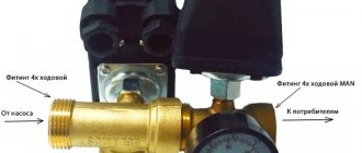
There are different ways to connect a water pressure switch to the plumbing system. The most convenient option is to install a special adapter with all the required outputs - a five-pin fitting. The same system can be assembled from other fittings, it’s just that it’s always easier to use a ready-made version.
It is screwed onto the pipe on the back of the housing; a hydraulic accumulator, a supply hose from the pump and a line that goes into the house are connected to the other outputs. You can also install a mud pan and a pressure gauge.
An example of tying a pressure switch for a pump
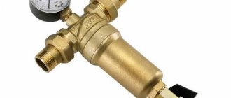
A pressure gauge is a necessary thing - to monitor the pressure in the system, monitor the relay settings. A mud trap is also a necessary device, but it can be installed separately on the pipeline from the pump. In general, a whole system of filters for water purification is desirable.
With this scheme, at high flow rates, water is supplied directly to the system - bypassing the hydraulic accumulator. It begins to fill after all the taps in the house are closed.
Possible faults
All device failures can be reduced to 3 main malfunctions:
- The pressure has dropped to the minimum level, but the pump does not start.
- The pressure has risen to the maximum value, but the pump does not turn off.
- The pump motor starts randomly and jerkily.
The repair should begin by setting up the relay. In rare cases, this method can restore normal operation.
When setting up a mechanical device, the cover is removed, this makes it possible to inspect and remove dirt.
To subsequently combat the malfunction, the device is dismantled. Check to see if the relay inlet is clogged. If inspection and cleaning do not produce results, contact specialists.
We recommend an article on the topic
Find and fix the problem, or what to do if the water pressure switch for the pump does not turn off