Water supply systems can have designs with varying degrees of complexity, but they all need to be managed. To facilitate manual control, special devices are used to automate startup and shutdown. They are called accumulator pressure switches. With their help, pumping equipment can be turned on and off if the water pressure level changes.
Pressure switch for hydraulic accumulator
- 1 Relay connection diagram for hydraulic accumulator
- 2 Setting the pressure switch for the accumulator
The device sets the minimum and maximum pressure values at which its operation is activated.
The operation of the relay is based on the principle: if the pressure indicator (P) decreases to the lower limit, then its contacts open and access to the flow of electric current to the pumping unit is opened; if the pressure reaches the upper limit, the contacts open and the pump is de-energized.
A relay indicator, made in the form of a sensitive membrane that bends under the influence of water, reacts to changes in P. It forces the contact mechanism to react by closing or opening.
A spring is used to counteract water acting on the membrane. It can be adjusted according to the needs of the system and the operating conditions of the pump. The pressure switch for the hydraulic accumulator is adjusted using a nut: if it is necessary to withstand greater pressure, the nut is tightened tighter; if a higher sensitivity of the membrane is required, the nut is loosened.
The mechanism uses another spring - a pressure differential. It allows you to adjust the difference between the upper and lower thresholds. The detuning is carried out by analogy with the first case; to increase the difference between the maximum and minimum thresholds, strong compression is required; a decrease will require weakening.
The relay is connected to the electrical supply and pumping device using 2 pairs of contacts. To connect to the pipeline, a special threaded connection is used, most often a thread with a diameter of 1/4 inch.
Today, the Russian market offers a wide selection of pressure switch models for hydraulic accumulators. The buyer can choose a product based on system requirements and financial capabilities. All devices can be divided into three main types, depending on their belonging to a particular price group.
- The most expensive . This class should include Grundfos FF 4–4, Grundfos FF 4–8, characterized by maximum pressure values of 4.8 atmospheres (the last digits in the marking indicate the value of the highest permissible indicator). The models have a simple design and do not require special knowledge to operate. They are quite simple to adjust, but only connect to low current. A regular 220 V power supply is not suitable for them. The difficulties that may arise when organizing catering and the rather high price make these models less popular. For the Grundfos FF 4–4 model you will need to pay about 3 thousand rubles, for Grundfos FF 4–8 about 8000 rubles. The buyer will pay part of the cost for the promoted brand.
- Pressure switch in the middle price category. Models MDR 5-5 and MDR 5-8 have an upper limit of 5 and 8 atmospheres. Designed for installation on top of a membrane tank. They are therefore particularly easy to adjust and use. They are more adaptable, as they can be connected to electrical networks with a voltage of 220 V (1-phase pump type) and 380 V (3-phase type). The products are reliable and have high current characteristics. Not a bad solution if you want to create a compact, high-quality system that is easy to maintain. However, those who are looking for a budget option may find these products expensive. For MDR 5-5 you will need to pay about 2100 rubles, for MDR 5-8 about 2900 rubles.
- Budget relays . As an example, we can consider MDR 5–5 devices, PM-5 relays, manufactured by a manufacturer from Italy. These pressure switches for hydraulic accumulators excellently perform their assigned functions, but the price is several orders of magnitude lower than that of products of the first price group. PM-5 can be purchased for about 330 rubles, which makes it popular among users of home stations. Reliable in operation, powered from a 220 Watt network. The disadvantages are that their connection is carried out according to a more complex scheme than MDR. They also have lower permissible current loads and do not have the ability to connect to a voltage of 380 V.
A relay of any price category, if used correctly, can cope with its functions perfectly. It is important to foresee the system loads in advance and select the product according to these parameters. The choice can be made independently or with the help of specialists.
What does hardware setup mean?
If it is impossible to connect to the central highway, owners of suburban areas create their own source of liquid consumption. This could be a well or an artesian well. Digging and arranging a mine leave their mark in the form of obtaining permits, geological exploration, drilling with the help of specialists or on their own, pumping, connecting junctions at entry points into the house, and if necessary, maintenance and repairs. However, there are also advantages if you install equipment equipped with additional functions, for example, a pressure sensor. It's incredibly convenient. Imagine, you need to go away on business for the whole day and you started an automatic washing machine and at the same time an irrigation system for watering green spaces. Constant monitoring of the functionality of the equipment is necessary, since the sensitive device will instantly respond to power surges and stop or start the equipment in time without your participation.
It turns out that the sensor is responsible for the frequency of activation of the system and is the most important control element, without which effective operation of the pump is impossible. It is this that gives the signal when to turn on and when to turn off, and the entire liquid start-up circuit is interconnected with the values placed on it.
What is a pressure switch
To adjust the water pressure switch in the hydraulic accumulator, you need to familiarize yourself with the operating principles and design of the equipment, as well as the rules for setting it up.
Maintaining constant pressure in the pipeline allows you to ensure the optimal level of the water column in the well shaft. Two parts supplied with the water pump are responsible for this - a pressure switch and a hydraulic accumulator. A relay is a small box containing electrical contacts. The water accumulator has a cylindrical shape and is designed to store a fixed volume of liquid.
There are several modifications of pumping equipment. The pump can be installed directly on the hydraulic accumulator; a pressure switch is already connected to it using an adapter called a five-piece. Separately, the five-piece is equipped with a pressure gauge; its panel displays the pressure inside the system.
The principle of operation of the pumping system is that the relay is equipped with contacts that are activated when certain pressure levels are reached.
Without a pressure gauge, it is almost impossible to adjust the relay for the hydraulic accumulator. Also, the initial filling of the accumulator with water must be done gradually, otherwise there is a high probability that the bulb (membrane) will be damaged. This is due to the fact that as a result of long-term storage of liquid, its walls stick together.
When it is necessary to adjust a water supply accumulator with a contact pressure switch
With proper setup, you can achieve the following results:
- Impeccable operation of the station without overload.
- Stabilization of the volume of liquid in the container.
- Increasing the service life of pumping equipment.
- High quality feed stream.
In the latter case, this is most relevant, since it is desirable to achieve a normal flow, without surges, for use at several points: cooking, taking hygiene procedures, pumping liquid into a swimming pool or outdoor shower, watering the garden and front garden, etc.
If you use the pump only in the summer, then monitoring the indicators is necessary before starting operation, since winter “stagnation” leads to dire consequences. During year-round living, it is advisable to adjust approximately once every ten days. This will protect your equipment from unexpected breakdowns at the most inopportune times, especially in cold weather, when repairs are difficult and require a lot of effort.
Connecting the accumulator to the system
Typically, the water supply system of a private home consists of:
- pump;
- hydraulic accumulator;
- pressure switch;
- check valve.
Connection diagram for hydraulic accumulator
This scheme may also include a pressure gauge for operational pressure control, but this device is not necessary. It can be connected periodically to carry out test measurements.
With or without five-pin fitting
If the pump is of a surface type, the hydraulic accumulator is usually placed next to it. In this case, the check valve is installed on the suction pipeline, and all other devices are installed in one bundle. They are usually connected using a five-pin fitting.
Five-pin fitting for piping the hydraulic accumulator
It has terminals with different diameters, just for the devices used for tying the hydraulic accumulator. Therefore, the system is most often assembled on its basis. But this element is completely optional and everything can be connected using ordinary fittings and pieces of pipe, but this is a more labor-intensive task, and there will be more connections.
How to connect a hydraulic accumulator to a well - diagram without a five-pin fitting
With one inch outlet, the fitting is screwed onto the tank - the pipe is located at the bottom. A pressure switch and pressure gauge are connected to the 1/4 inch outlets. The remaining free inch terminals are connected to the pipe from the pump and wiring to consumers. That's all for connecting the gyroaccumulator to the pump. If you are assembling a water supply circuit with a surface pump, you can use a flexible hose in a metal winding (with inch fittings) - it is easier to work with.
A visual diagram of connecting the pump and accumulator - use hoses or pipes where necessary
As usual, there are several options, the choice is yours. The hydraulic accumulator is connected to the submersible pump in the same way. The whole difference is where the pump is installed and where the power is supplied, but this has nothing to do with the installation of the accumulator. It is placed in the place where the pipes from the pump enter. Connection is one to one (see diagram).
Connection diagram of a hydraulic accumulator to a submersible pump
How to install two hydraulic tanks on one pump
When operating the system, sometimes owners come to the conclusion that the available volume of the accumulator is not enough for them. In this case, you can install a second (third, fourth, etc.) hydraulic tank of any volume in parallel.
Connecting several hydraulic tanks into one system
There is no need to reconfigure the system; the relay will monitor the pressure in the tank on which it is installed, and the viability of such a system is much higher. After all, if the first accumulator is damaged, the second one will work. There is another positive point - two tanks of 50 liters each cost less than one of 100. The point is that the technology for producing large-sized containers is more complex. So it is also more economical.
How to connect a second accumulator to the system? Screw a tee onto the input of the first one, connect the input from the pump (five-pin fitting) to one free output, and connect the second container to the remaining free one. All. You can test the circuit.
Instrument location
A hydraulic accumulator is often confused with a storage tank. Outwardly, they are similar, both are made of metal, have the same shape, only the GA is a more complex device and consists of parts that significantly expand its functionality:
- air valve for bleeding;
- five-outlet pipe (tee);
- flat flange with holes for bolts;
- couplings;
- worker node control module.
GA is sometimes called a membrane tank and this is also correct. After all, the device is divided into two parts by a rubber part; air or inert gas is pumped into one, and the second is designed to supply drinking liquid, which is under constant pressure.
When installing a water supply system, the device is mounted immediately after the pump on an internal or external water supply system (the specific layout depends on the characteristics of the complex). The principle of operation of the hydraulic accumulator is as follows. From physics lessons we know that water cannot be compressed, but air masses are subject to compression. Therefore, the container is separated by a membrane, which can stretch as moisture enters, while compression is created in the air chamber due to a decrease in volume. When a certain value is reached, the automation is triggered and the pump is turned off. After this, you can use some liquid. When the level decreases, the same equipment turns on the pumping device.
Pressure value in the accumulator
Optimal pressure in the accumulator ensures constant water pressure and prevents wear of system parts
Inside the hydraulic tank there are two media - air or gas and water, filling the rubber membrane. The principle of operation of the device: when the pump is turned on, the liquid enters the stretchable container. The gas is compressed and its pressure increases. Air pressure pushes water from the membrane into the distribution pipes. When the indicator for which the automation is configured is reached, the device turns off. Water consumption comes from the hydraulic accumulator reserve. A decrease in liquid volume leads to a drop in pressure and the pump restarts. The operation of the hydraulic accumulator is controlled by a pressure switch.
The main function of the pressure in the accumulator is to create optimal conditions for the operation of the pumping station. The air pressure prevents the mechanism from turning on and off after each opening of the tap. Installing a storage tank in the water supply system also solves other problems:
- Prevention of sudden changes in pressure in the pipeline (water hammer), causing damage to pipes and mixers.
- Extending the service life of pumping equipment, preventing wear of parts and components.
- Creating a reserve of water inside the tank, which is used during a power outage.
The choice of tank volume depends on the power and type of pump. Units with a built-in frequency converter have a smooth start. A tank with a minimum capacity (24 l) is sufficient for them. The disadvantage of the mechanisms is their high cost; they are rarely used in private households. A common option is budget well pumps that provide maximum power when started. They quickly create high pressure in the pipes. The membrane tank must compensate for it.
When operating surface pumps with a power of up to 1 kW, it is recommended to install a 24-50 liter storage tank. Submersible units with a power of 1 kW require a hydraulic accumulator of 50-100 liters. Mechanisms with professional characteristics are equipped with tanks from 100 liters. The size of the storage tank is affected by the average water consumption.
The principle of operation of the mechanism
If the compression is below the minimum threshold, the sensor closes the circuit and supplies power to the pumping equipment. In this case, the springs connected to the membrane react to pressure surges: increasing the parameter leads to compression of the spiral, decreasing the value leads to stretching. During these actions, the contacts react to movement and turn on/off depending on the phase.
In fact, the device copies a classic gearbox, only the rod controls the contact group.
How to correctly set the pressure switch on a water accumulator - preliminary steps
Make sure the entire system is passable. Check for mechanical contamination. Assess the serviceability of the storage tank, paying special attention to the integrity of the membrane. Check the operation of the filtering equipment (ingress of solid particles can quickly damage rubber elements). After this, you can begin entering the necessary parameters.
Place of the device in the water supply system
The hydraulic accumulator (HA) consists of a container, a bleed valve, a flange, a 5-pin fitting (tee) with couplings for connection, as well as a pressure switch (control unit), which sets the rhythm of all work.
- main control element
- ensures work without overloads
- controls optimal filling of the tank with water
- extends the service life of the membrane and all equipment in general
A pressure gauge that shows the pressure in the tank is included in the kit or can be purchased separately.
The pump pumps water out of the well and directs it through pipes. Next, it enters the GA, and from it into the home pipeline. The purpose of the membrane tank is to maintain stable pressure, as well as the operating cycle of the pump. There is a certain maximum activation for it - about 30 per hour. If exceeded, the mechanism experiences stress and may fail after a short time. The water pressure switch must be adjusted so that the devices operate as expected, without exceeding the critical load.
Setting up a storage tank means creating the required number of atmospheres in it and correctly setting the pump response thresholds
Connection instructions
Setting modes will depend on the location of the storage tank, the maximum height of the distribution point and the number of consumers at the site. Each of these standards will affect the stable flow, so the extreme value will have to be set within certain limits in order to achieve the desired result in all places. It should be noted that the technical characteristics of the devices must correspond to the operating parameters. This applies to a greater extent to the volume of consumption. If the flow rate is high, then with a small storage tank the system will constantly turn on and off. At the same time, the flow in the tap changes as expected, which is very unpleasant when taking a shower.
Inside the container
For optimal functioning, it is necessary to have the maximum possible storage reserve. Therefore, a pressure 10 percent less than the shutdown level is pumped into the air cavity. This allows most of the tank to be used for storage (compressing the gas to 10% of the volume creates a force within two atmospheres).
The correct operation of the water supply is greatly influenced by one-time consumption. Theoretically, approximate values can be calculated based on the following coefficients, which reflect the frequency of use and volume of consumption.
| Appliances used in everyday life | Utilization factor in Cx |
| Toilet with tap | 3 |
| Shower cabin | 2 |
| Bathroom | 2 |
| Kitchen sink | 6 |
| Bidet | 1 |
| Washbasin in the bathroom | 2 |
| Washing machine | 2 |
| Dishwashing machine | 2 |
| Watering valve | 2 |
As the number of floors increases, the maximum shutdown threshold also increases, since otherwise you may experience temporary interruptions in sources on the second and third floors. The height difference is approximately three meters, which means that the minimum value should be 0.3 atm less.
Cutoff points
In order for the stream from the tap to have the same parameters, it is worth setting the turn-on moment at the pressure gauge mark of 1 atmosphere. Each floor increase requires an increase of 0.3 atm. This is necessary so that the water does not stop flowing at the top point even at the minimum value.
AMETHYST - 02 M Residential building for up to 10 people or up to 2 cubic meters/day.
Aeration unit AS-1054 VO-90
Main table dispenser AquaPro 919H/RO (hot and cold water)
The second standard is accepted as the first plus one. That is, if the switching level is 1.6, then the pump should turn off at 2.6 atmospheres. All devices have slightly different technical characteristics (technical characteristics) and not every model is capable of ensuring uninterrupted supply in a multi-story building with high flow rates.
Settings
Before adjusting the relay, you need to take into account that its values are inextricably linked with the pressure inside the membrane tank. First you need to create the required amount of pressure inside it, and then move on to working with the control in question.
The adjustment is carried out in 3 stages:
- pressure inside HA
- pump start level
- shutdown mark
For optimal operation, it is necessary to adjust the parameters several times experimentally, taking into account the water flow, the height of the pipes and the pressure in them.
Indicators inside the accumulator
It is advisable that the pressure adjustment in the accumulator take into account the following examples and rules:
- for a one-story house, 1 bar is enough, and if the tank is installed in the basement, then add 1 more
- the value must be greater than at the highest point of water intake
- how many atmospheres should be inside the container is determined by the following formula: add 6 to the height of the pipes to the highest point of water intake and divide the result by 10
- if there are many consumption points or the branching of the pipeline is significant, then a little more is added to the resulting figure. How much to add is determined empirically. There is the following rule for this. If the value is too low, then water will not be delivered to the devices. If it is too high, the HA will be constantly empty, the pressure will be too strong, and there will also be a risk of membrane rupture.
In order to increase the pressure in the accumulator, air is pumped up with an ordinary bicycle pump (there is a special spool on the body); to lower it, it is vented. The pneumatic valve for this purpose is located under the decorative trim. The procedure must be done in the absence of water pressure, which requires simply closing the taps.
The value of the indicators is determined by a pressure gauge connected to the spool. The correction is made after the pump has turned off. The pressure difference is created by opening the tap at the nearest point.
Manufacturers standardly set the pressure in the tank to 1.5 - 2.5 bar. Its increase reduces the usable space inside the container and increases the pressure in the system - this must be taken into account when calculating.
Basics of adjusting thresholds
There are two springs with nuts: the larger one is responsible for the values for turning off the pump, the smaller one is for turning it on. The bolts are loosened or tightened, thereby making adjustments.
Setting up the accumulator pressure switch will be of high quality if you follow these rules:
- the average recommended difference between the values for turning the pump on and off is 1 - 1.5 atm
- the pressure inside the HA must be lower than the set value to turn on the pump by 10%. Example: if the activation mark is set to 2.5 bar, and the switch off mark is set to 3.5 bar, then there should be 2.3 bar inside the container
- the hydraulic accumulator and control unit have their own load limits - when purchasing, you need to check whether they coincide with the calculations for the system (pipe height, number of intake points, flow rate)
The mechanism in question controls the maximum and minimum pressure in the tank. It maintains the difference in its values when the station is activated and switched off. The limit of its settings depends on the power and hourly flow rate of the pump.
Factory parameters are indicated in the product data sheet. Usually they are like this:
- limit limits – 1 – 5 atm
- pump operating range – 2.5 atm
- starting point – 1.5 atm
- maximum switch-off level – 5 atm
Preparation and example of setting the required values
Preparation:
- tank is connected
- the control unit is adjusted under pressure, the system is not disconnected from the power supply
- inside the unit the pressure should be 10 - 13% lower than that of the pumping station. That is, approximately 0.6 - 0.9 atm than the mark at which the engine turns on
- all taps are closed
- the set level is checked with a pressure gauge within an hour to make sure there are no leaks
- remove the block housing cover to have access to the nuts and observe the springs
Setting with an example of setting marks of 3.2 atm to turn off and 1.9 atm to turn on (two-story house):
- Start the pump to determine the pressure in the system. It should fill the storage part of the device and increase the pressure.
- They determine at what pressure gauge reading the shutdown will occur (usually no more than 2 atm.) When exceeded, a small spring comes into action, which is clearly visible.
- The motor is stopped above 3.2 - 3.3 atm, this figure is reduced by rotating the nut on the small spring a quarter turn, since it is very sensitive, until the motor turns on.
- They check with a pressure gauge: 3 - 3.2 atm will be enough.
- Turn on the tap to relieve the pressure and so that the HA is freed from the liquid and record the pump activation mark with a pressure gauge, usually 2.5 atm - the lower pressure indicator has been reached.
- To reduce the lower threshold, rotate the large spring bolt counterclockwise. Next, start the pump until the pressure rises to the required level, after which you need to check the pressure with a pressure gauge. An acceptable value is 1.8 - 1.9 and the nut is rotated clockwise.
- Once again, adjust the small spring a little, clarifying the already set thresholds.
The adjustment bolts are very sensitive - turning just 3/4 of a turn can add 1 atm. The pressure of the switched-on pump should be 0.1 - 0.3 atm higher than in an empty storage tank, which will prevent damage to the “bulb” inside it.
The setup process in brief
For a better understanding of how to set up a pressure switch, we will outline the process more clearly:
- pump activation mark (minimum pressure): rotating the large spring bolt clockwise increases the starting mark, counterclockwise decreases it;
- value for shutdown: move the small spring, when tightening - the pressure difference increases, when unscrewing - the actuation mark decreases;
- the result is checked by opening the tap and draining the water, recording the moment the pump is turned on;
- The internal pressure force is adjusted by deflating or pumping air and checking this with a pressure gauge.
Increasing the factory switching parameters (above 1.5 atm) creates a risk of critical load on the hydraulic tank membrane. The operating range of the pump is adjusted taking into account the maximum possible load for the water fittings. The sealing rings of household taps can withstand a maximum of 6 atm.
How to properly adjust a pumping station with an automatic water pressure switch on a hydraulic accumulator
The operating parameters are set by tensioning or loosening two springs, one of which is responsible for the upper level of permissible pressure and turns off the pump. The second, usually of a smaller diameter, turns on the supply of electricity at the moment of reduction to a minimum. The values required for installation will depend on the characteristics of the water supply system, the number of consumers, number of floors and some other indicators. But it is worth remembering that you cannot exceed the permissible dimensions from the manufacturer. It would be most correct to make adjustments with a reduction of 10%.
How to set up a mechanism with a 50 liter expander
The recommended switching point is around 2 atmospheres. When this reading occurs, the pump should turn on. If operation occurs at large values, then adjustments need to be made. The preliminary action is to fill the chamber with air while the liquid is drained. The parameter on the pressure gauge should be 1.5 Atm. With this adjustment, maximum flow of accumulated liquid is ensured. The shutdown point is usually taken one unit higher. This allows you to fill the tank as much as possible without subjecting the membrane to extreme stretching.
How to adjust water pressure in a water supply accumulator with an 80-liter tank
These models are used for active use of the plumbing system and in private houses with two or more floors. The manufacturer has included high strength characteristics in the device, so it is permissible for them to increase all values by 0.5 atmospheres. This ensures a stable supply of liquid to a height of up to 10 meters.
The adjustment is made according to the same scheme, only all sizes are set half a point larger.
Cost of relays and hydraulic accumulators of some manufacturers
Relay models can be purchased relatively inexpensively. Usually the cost of products does not exceed one thousand rubles. However, electronic analogues may have a higher price, as they allow for more precise adjustments. The table shows models of some manufacturers and their prices.
Pressure switch Gilex RDM-5 presented
| Image | Model | Dimensions in millimeters | Price in rubles |
| Gilex RDM-5 | 110x110x70 | 900 | |
| Danfoss KP1 | 107x65x105 | 1 570 | |
| Belamos PS-7 | 150x80x150 | 575 | |
| Caliber RD-5 | 103x65x120 | 490 |
Related article:
Water pressure regulator in the water supply system. If the water pressure is normal or even strong, then you simply need this device. You will find out why in our separate review.
As for hydraulic accumulators, their cost can be noticeably higher. It mainly depends on the volume of the structure. A large tank can significantly reduce the number of work cycles. However, there is not always enough space for it. The table shows prices for hydraulic accumulators for water supply of different sizes.
Hydraulic tank Poplar 24 l
| Manufacturer | Volume in liters | Cost in rubles |
| Gilex | 24 | 1 400 |
| 50 | 3 500 | |
| 100 | 6 300 | |
| Poplar | 24 | 1 100 |
| 50 | 2 900 | |
| 100 | 5 100 |
Note! On average, a hydraulic accumulator with a capacity of 50 liters is usually enough for a family of 4-8 people. If there are fewer people living, a capacity of 24 liters is purchased, and if there are more people, 100 liters.
Hydraulic accumulator Gilex, holding 24 l
Indicators inside the tank
The key point is to create a cushion of air. The required parameter is achieved by pumping atmosphere into a special spool located at the point of the container opposite from the automation. This is very easy to do using a car pump and battery. Each model has its own value and usually ranges between 1-2 atmospheres. This figure is also affected by the design of the entire water supply.
Correctly setting up the hydraulic accumulator and pressure switch
If the setting range is small, then the automation works too often, since the volume of the drinking resource is very small. But there is a minimal difference in pressure. The expanded gap allows more moisture to accumulate, but the flow will differ significantly in different phases. For a comfortable supply, you should choose the “golden mean”. Typically, the necessary data is described in the technical documentation of the device. We recommend following the information from the manufacturer.
Preparing to set parameters
Let's assume that you have installed the entire system and you are faced with the task of configuration.
Your actions:
Main table dispenser AquaPro 929CH/RO (cooling/heating)
Floor dispenser AquaPro 311 (empty, without cooling)
Floor-standing dispenser AquaPro 6207CH (cooling/heating/room temp.)
- Drain the water.
- We pump the chamber with a car pump to a value of 1.5 atmospheres.
- We turn on the equipment and control the moment of shutdown.
- We adjust this point to 2.5-3.5 Atm.
- We turn on the nearest tap and detect the moment the electricity is supplied.
- We bring the values to two units.
- We check the correct operation.
- We make additional adjustments for convenient consumption.
To increase the pressure, if necessary during the process, it is worth tightening the spring with a wrench clockwise. To reduce, both spirals are tightened in the opposite direction. After the above operations, the necessary indicators are displayed on the pressure gauge - feel free to connect the pumping system and use it on an ongoing basis. Otherwise, you need to start all over again.
How to set up a 50 liter system?
After the calculations, it is necessary to measure the air pressure inside the station, the value of which should not exceed 1.5 atm .
This is the indicator that will ensure good water pressure. The higher the parameter, the less water can flow.
To measure, you can use a car pressure gauge, which helps calculate the indicator with the least inaccuracy.
After determining the air pressure, you must:
- Start the pump to establish pressure in the system.
- Determine at what point on the pressure gauge the shutdown occurs.
- Set the mark for disabling the mechanism.
- Turn on the tap so that the accumulator gets rid of moisture and record the indicator.
- Adjust the small spring to the formed thresholds.
| Index | Action | Result |
| 3.2-3,3 | Rotate the screw on a small spring until the motor is completely turned off. | Decrease in indicator |
| Less than 2 | Add pressure | Increase in indicator |
The recommended value is 2 atmosphere.
By adhering to these recommendations, you can establish acceptable performance of the water supply system.
Your actions during maintenance or repair
During operation, monitor the operation of the entire unit, since the efficiency and quality of the supplied water depends on this.
It is advisable to carry out maintenance of the device approximately once a year:
- Clean and lubricate all contacts.
- Check mechanical sensitive elements and, if necessary, adjust to the required parameters.
- Watch how the nuts are tightened. Tightly twisted ones will not allow the device to function correctly.
If, when inserting the equipment, the device does not hold pressure or some other problems appear, then you should not immediately change the mechanism to a new model. Everything can be fixed.
To do this, we recommend washing the membrane that is clogged with sand, dust or other debris. The element is held on by four bolts. You need to unscrew them, remove the cover and pull out the cover with the inlet pipe. Remove the element, clean and dry. Assembly is carried out in reverse order. Before the test run, set the thresholds again, as we indicated above.
Another important point worth paying attention to. Air should not accumulate in the pipeline; it must be vented periodically, approximately once every three months.
Tips from
To ensure that you do not have problems with the operation of your equipment in the future, we recommend:
- It is better to connect the sensor via a separate line with its own residual current device.
- The relay must be grounded. For this purpose, manufacturers have prudently made special terminals.
- Do not tighten the nuts all the way, this will lead to operation of the device with large errors.
- If moisture appears on the housing, immediately turn off the pumping equipment. This indicates that the rubber membrane has broken. In this case, the unit cannot be repaired; it must be replaced with a new one.
- The presence of filter elements is a must! If they are not included with the station (which is unlikely), then buy them and install them. Otherwise, you will ruin expensive equipment.
We connect the pressure switch to electricity
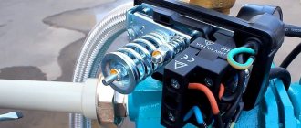
Contact group of a real relay. Wire connections visible
Here you can see how the contacts are divided into pairs. Pairs are shown by red arrows. The wire from the socket can be connected to the lower contacts, and the wire to the pump to the upper ones, or vice versa
Electrical diagram of a pressure switch
Here I have schematically shown those same pairs. The dashed line shows that the contacts open and close synchronously
These are the same contacts.
They move up and down and close contact pairs
The pressure switch has either one, which is less common, or two, which is more common, groups of contacts. Until we created pressure. these contacts are closed. During pressure build-up, the contacts open. How to find the right contacts? Ideally, the contacts should be indicated in the instructions. If not, they can be identified by carefully inspecting the relay. I think you can find a place where you need to connect the wires. This is a completely common thing. So somehow these contacts should be marked. How are they marked? Whatever. The main thing is to identify groups of contacts. The pair can be marked with the words LINE and LOAD, or maybe something else, for example MOTOR and LINE. If you are familiar with the basics of electricity, then you can literally find the contacts by eye and check your find with a probe. Moreover, you can press the contacts lightly with your finger and they will open.
Relay FSG-2 - electrical connections
The wires go to the left to the 220 volt outlet, and to the right to the pump motor. Or it can be the other way around. The sum, as they say, does not change by changing the places of the terms.
Electrical Wire Requirements
The wire with which we connect the pump must match the power of our pump. Let's assume that our pump is no more powerful than 1500 watts. Then it is best to use a copper two or three core wire with a core diameter of 1.5 mm or more. If we have grounding, then we use a three-wire wire. If we don’t have grounding and we don’t know what it is, then we consult with an electrician who lives next door and find out what to do in this case. If you are a principled opponent of grounding, then forget about it, although it is very dangerous, and I do not recommend it!
Diameter and area of the core I indicated the diameter of the core above. The store often indicates the cross-sectional area of the core. Area is correct. If we have a diameter of 1.5 mm, then the area is calculated as pi-de-square-by-four, namely the square of the diameter multiplied by pi (3.14) and divided by 4. For a diameter of 1.5, the area will be equal to 1.76 mm. Take a caliper and a calculator with you to the store sometime and see how much the diameters of the wires correspond to their cross-section indicated on the labels. I think you're in for a surprise!
Important!!! Electric motors, especially old and well-established ones, are characterized by the fact that they can create interference on the body. Then these signals are transmitted through the water to the plumbing parts and, to put it mildly, can tickle you. Or it might crack due to electric shock. Moreover, in a particularly unfortunate set of circumstances, you can suffer greatly from this. I highly recommend, if not grounding, then at least grounding your pump. And experienced electricians advise both zeroing and grounding. But before grounding, make sure that your electrical wiring is wiring with a solidly grounded neutral. Most likely this is true, but who the hell isn’t kidding? And if in doubt, call, preferably, an electrician!
We connect 220 volts
We take our wire with 220 volts. We disconnect it from the electricity!!! We screw one core of this wire to the free contact of one pair, and the second core of the wire to the free contact of the second pair of contacts. It doesn't matter what they are called. You can screw our wire to the MOTOR contact on one pair and to the LINE contact on the other. The main thing is not to screw both ends to the contacts of one pair, otherwise we will immediately get a short circuit. We screw the grounding wire to a special screw on the iron body of the pressure switch. Grounding is indicated by a special symbol.
Connect the relay to the pump
Take a piece of wire. The wire must have cores of a suitable diameter, see above. Cut a piece of the required length from this wire. We screw the cores of our piece to the free contacts. It would be nice to keep the color of the veins. We screw the second end of the wire to the pump contacts. We mean that the blue wire is usually marked with the letter N. It is better to follow this rule. The hope remains that when wiring electricity, earth and phase were carried out according to generally accepted rules. The ground wire is usually yellow-green braided. Should the relay ground pin be connected to the pump ground pin? I don’t connect, but you do as you wish.