How does a heat pump work?
The operation of a heat pump is based on a unique Carnot cycle, with its own circular process. According to this scheme, the heat pump is capable of pumping in a circle the dissipated heat taken from the ground, water or air.
This approach makes it possible to collect almost 75% of the thermal energy by the heat pump, but 25% of the energy is required to operate the equipment itself. For this reason, a heat pump cannot do without the consumption of electricity, which is necessary for its efficient operation. At the same time, consuming only 1 kW of electricity, the heat pump is capable of delivering 5-7 times more.
The operating principle of a heat pump is very similar to a regular refrigerator or air conditioner that we are used to using every day. For example, deep underground (below the freezing level of the ground) or at the bottom of a reservoir, pipes are laid according to the scheme of heated floors, through which the coolant circulates all the time.
The temperature underground, at the depth of which the pipes are laid, is always constant, with a positive mark. Therefore, the coolant does not heat up too much, only by a few degrees. Then, once it enters the heat pump's evaporator, it releases the collected heat to the internal circuit, and this is where the fun begins.
In the internal circuit of the heat pump there is freon (refrigerant), which enters the evaporator under high pressure and takes away part of the heat given off by the coolant to the walls of the evaporator. The refrigerant then enters the heat pump's compressor, where it is compressed, heated, and pushed into the condenser.
Already in the heat pump condenser, heat is taken directly into the heating or hot water supply system of the house (via a heat exchanger). The heat transfer cycle then repeats over and over again, which is how a heat pump works.
Types of heat pumps
Today, there are different types of heat pumps, for example, ground-water or air-to-air heat pumps. Let us briefly consider the existing types of heat pumps:
Ground-to-water heat pump: These are geothermal heat pumps that are designed to extract heat from the ground and transfer it into the house, passing it through the coolant that circulates in the heating system.
Water-to-water heat pump: heat, when using a water-to-water heat pump, is taken in this case from a well or well. To do this, a special hydraulic unit installed in the heat pump pumps groundwater, takes away heat and discharges it back into the well. This type of heat pump is notable for the fact that it is possible to use an existing well on the site in order to create geothermal heating in your home.
Air-to-water heat pump: the heat source in this type of heat pump is the surrounding air. Consuming only 1 kW of electricity, an air source heat pump can increase it to 5 kW for heating needs and hot water heating.
Air-to-air heat pump: The operating principle of an air-to-air heat pump is similar to that of a home air conditioner, which functions to heat rooms. The only difference is in operating efficiency, since air-to-air heat pumps are almost 3 times more efficient than any air conditioners with a heating function.
Of course, heat pumps, like other sources of alternative energy, have a future. When the oil and gas reserves on Earth are depleted, a reboot will be needed, and then the energy of the sun, earth and wind will come to the rescue, allowing all of humanity to survive.
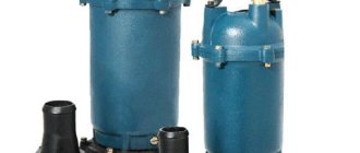
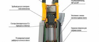
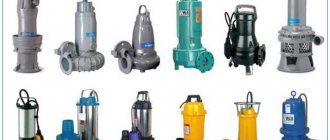
Design features of deep-well pumps
The design of a deep-well pump and its design features are largely determined by the principle of operation and the type of drive electric motor of this hydraulic machine. When using such pumps, the pumped liquid medium is collected through a special pipe placed in the shaft of the serviced well or in a well. An electric cable placed in a protective sheath is responsible for powering the drive motor, located at a certain depth.
In the design of a centrifugal type well pump, two main parts can be distinguished:
- drive motor, which can be built-in or external;
- directly the pumping part of the equipment.
Design of a centrifugal well pump
If the pump drive motor is built-in, it is usually located at the bottom of the device. Water intake when using pumps of this type can be carried out both through the upper and lower parts of their housing. In this case, preference is given to collecting the pumped liquid through the lower part of the housing, as this allows you to clean the deep part of the well from silt and sand accumulating in it. Submersible pumping devices, which is very convenient, are cooled by the liquid medium in which they are placed. This allows you to protect such devices from overheating, which can quickly render them unusable. Centrifugal-type deep-well pumps, although more complex in design than vibration devices, are characterized by higher reliability, productivity and a longer service life.
The pump suspension must withstand a load exceeding the weight of the pump by 5–10 times
The main design elements of vortex submersible pumps are a housing, a special glass, a drive motor and a vibrator. The vibrator in these devices is the most complex structural element, consisting of an armature, a rubber shock absorber and adjusting washers. The necessary conditions for drawing fluid from a well, carried out by a vibration pump, are created by its rubber shock absorber, which compresses and decompresses during operation of such a device.
A mandatory element of equipping submersible pumping equipment is a coarse filter that protects the inside of such devices from the ingress of solid impurities contained in the pumped medium. To ensure more efficient operation of submersible pumping equipment and ensure its protection from negative factors, various sensors are used that automatically stop the pump when emergency situations arise (the content of silt and sand in the pumped liquid is too high, the water level in the well decreases, etc.).
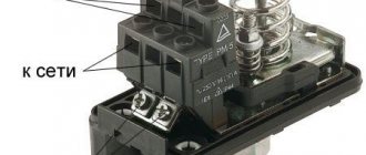
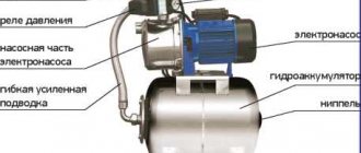
The principle of operation of the circulation pump
To understand how a circulation pump works, you do not need to be a great specialist. Its task is to overcome friction inside the heating system and organize non-stop movement of the coolant. The motor uses a rotor to push the liquid through the pipes. If the circulation pump does not work, the coolant will continue to move through the system by inertia for some time, and then stop completely. Pumps with two types of rotor, so-called dry or wet, are produced on an industrial scale. The first type of rotor is used for heating large industrial premises, where the noise level of a running pump is not of fundamental importance. The high level of performance of the device compensates for the need for constant lubrication of the moving parts of the pump. A pump with a wet rotor is used for heating residential premises. The coolant in which the rotor is immersed simultaneously lubricates and cools the engine. The absence of a fan and the presence of a protective casing makes the operation of the unit so quiet that you can hardly hear the circulation pump working.
The principle of operation of a circulation pump with a wet rotor is such that the unit can operate in a room with low air pollution and pump purified water or a water-liquor mixture. Oil is not used as a coolant in a heating system with a circulation pump.
Despite the seemingly simple principle of operation of the circulation pump, you can select the right device only with the help of a specially trained employee who can correctly calculate the parameters of the required unit and connect it to the heating system. A pump with excessive power will create unpleasant noise in the heating system, caused by an increased speed of coolant movement and uses more energy.
The question of the need for a pump power reserve remains controversial among experts. Some believe that the pump operates at full capacity only a few days a year, and the rest of the time it consumes additional energy, which is absolutely not rational. Others argue that working at the limit of its capabilities, the unit will quickly wear out and fail.
To correct the operation of the pump, devices with power control are produced. The pump can be set in manual or automatic mode. Manual adjustment has three rotor speed modes, each of which affects the speed of coolant movement. In warmer weather, you can save energy by setting the pump to its lowest setting.
More expensive modern pumps with automatic power control can be successfully used in a heated floor system or heating system with heating temperature regulators on radiators. Automation is able to detect the slightest changes in the system and adjust the corresponding pump settings.
How to install a heating circulation pump
For owners of country houses with a local heating system, the issue of uniform distribution of heat between all rooms is especially acute. For this purpose, natural coolant circulation systems are used.
The circulation pump gets hot
In heating systems, circulation pumps are used to ensure uniform circulation of the coolant. Pumps pump working fluid from the boiler to heating devices, and when the liquid cools, back to the boiler. All.
Vortex pumps - application and description
Vortex pumps are used to pump clean water without abrasive inclusions and liquids whose chemical composition is safe for the device. Vortex pumping units are quite reliable and relatively simple.
Application of vortex pumps
Vortex pumping units are used in the following systems:
- in irrigation systems;
- in sewerage and water supply units;
- in industrial and technological processes.
Vortex installations are also used in fire suppression, chemical water treatment, heating and ventilation, as well as in oil refineries and alcohol factories, for filling and emptying tanks.
Centrifugal
The most common type of feed device in boiler systems is the centrifugal pump. Centrifugal feed pumps are manufactured as single or multi-stage depending on the flow rate and operating pressure and are driven by an electric motor or steam turbine.
The pump consists of impellers rotating on a shaft and a volute casing. Before starting, the pump is filled with water. During operation of the pump, water enters it through a suction pipeline with a suction valve and a mesh that protects the valve from clogging. Falling on the impeller blades in the axial direction, water is picked up by the blades and, under the action of centrifugal force, is thrown into a snail-shaped channel surrounding the rotating wheel, and then into the discharge pipeline.
When water is ejected from the impeller, a vacuum is created in its central part, due to which, under external pressure, water flows through the suction pipeline into the pump. Thus, as the impeller rotates continuously, water continuously moves through the pump.
As the water leaves the pump, the speed of the water increases and the pressure decreases. In order for water to enter the boiler, the discharge pressure must be greater than the steam pressure in the boiler. To reduce the speed of movement and increase the discharge pressure, most pumps are equipped with a guide vane (and here about heat exchangers), which is a disk with blades bent in the direction opposite to the direction of bending of the impeller blades. The outlet sections of the guide disk blades expand.
To increase the pump flow, the impeller is designed with double-sided suction, that is, water is supplied to it from both sides. The pressure created by one impeller usually does not exceed 50 m. To create large pressures, centrifugal pumps are made with several impellers located in series one after the other on one common shaft. Water sequentially passes from one wheel to another. The head created by a multistage pump is equal to the sum of the heads created by each impeller.
The centrifugal pump is equipped with pressure gauges and valves on the suction and discharge pipelines, a check valve on the discharge pipeline, and air release valves in the upper part of the housing of each stage.
Compared to piston pumps, centrifugal pumps have a larger flow rate, smaller overall dimensions, and create a more uniform water supply (without shocks).
The disadvantages of centrifugal pumps are the mandatory filling of the pump with water before starting, the high cost of operation at high pressures, and the dependence of the suction height on the water temperature.
Ejector
The greatest depth from which surface vortex and centrifugal pumps can lift water is 8-9 meters; it is often located deeper. To “get” it from there, an ejector is installed on the pumps. This is a specially shaped tube that, when water moves through it, creates a vacuum at the inlet. So such devices also belong to the category of self-priming. An ejector self-priming pump can lift water from a depth of 20-35 m, and this is more than enough for most sources.
Connection diagram for a remote ejector for wells of different diameters - two-inch on the right, four-inch on the left
The disadvantage is that in order to ensure operation, part of the water must be returned, therefore, productivity is significantly reduced - such a pump may not provide a very large water consumption, but no less electricity is spent to ensure operation. When installing an injector in a well or well of sufficient width, two pipelines are lowered into the source - one supply of a larger diameter, the second, return, of a smaller diameter. An ejector is connected to their outputs, and a filter and check valve are installed at the end. In this case, the disadvantage is also obvious - double pipe consumption, which means a more expensive installation.
In small-diameter wells, one pipeline is used - the supply one, and instead of the return line, the well casing pipe is used. In this way, a rarefaction zone is also formed.
How does VVN work?
A liquid ring vacuum pump is the most popular type of equipment used for pumping gaseous media from closed spaces. For the operation of such devices, a liquid working medium is needed, which is mainly water (less commonly, oil, antifreeze, alkalis, acids and other substances). The design of pumps of this type includes a wheel with blades, which is the main working body of such devices.
The principle by which VVNs work is quite simple. It consists in the following.
- Under the influence of the rotation of the blade wheel, which creates centrifugal force, the liquid is thrown towards the walls of the working chamber, forming a water ring along its inner perimeter.
- In the central part of the working chamber, as a result of the above-described process, a vacuum zone is created, which ensures the suction of the pumped gas medium into such a chamber through the inlet pipe.
Operating principle and main parts of the VVN pump
It should be kept in mind: the operating principle of vacuum pumps of this type implies that the liquid working medium is constantly heated, so it must be changed regularly.
The design and operating principle of liquid ring vacuum pumps are quite simple, which ensures high reliability of such equipment, as well as ease of operation, maintenance and repair.
Liquid ring vacuum pumps do not require purification of the pumped gases and can operate around the clock
Areas of application
The liquid pump can be used to solve a wide variety of problems. The created design is characterized by high versatility. However, the presence of a moving element and the use of sealing rings when creating a piston makes it impossible to use a piston pump for pumping large volumes of liquids.
Application of piston pump in gardening
Application of a pump for pumping water
Considering the scope of application, we note the following points:
- The materials used in manufacturing can withstand the effects of various chemicals. That is why piston pumps are used to work with various types of fuel, explosive mixtures and chemically aggressive environments.
- There are quite a large number of models on sale that can be used for work at home.
- In the food industry, the design is also used extremely often. This is due to the delicate effect on the pumped medium.
Piston pump in the oil industry
In the manufacture of a structure, a variety of materials can be used, which determine the scope of application.
How does a circulation pump work?
The private houses in which our parents live were built with their own hands, which is noticeable in the illiterate layout of the premises, not always straight windows and doors, and littered walls. Everyone installed the heating as they understood, the principle was the same: the slope must be maintained so that water could continuously circulate through the system.
The operation of the circulation pump takes us into a new era of heating systems. Its presence in the system makes it much more economical. The diameter of the pipe can be significantly smaller, which significantly reduces the volume of coolant. The liquid moves through the heating system at a certain speed, which allows you to heat the rooms evenly, maintain the most comfortable temperature in them, and, if necessary, it heats up quite quickly. The automatic operating mode of the circulation pump allows the device to instantly respond to various changes in the system, changing the device settings and making the operation of the heating equipment more economical. Heating a house with several floors is unthinkable without such a pump, and the continuous circulation of the coolant, in addition to all these advantages, also protects the heating boiler from erosion.
Advantages and disadvantages
A piston liquid pump is characterized by a fairly large number of advantages and disadvantages. The advantages include:
- Simplicity of design. As previously noted, similar piston pumps were manufactured several decades ago and their design has changed insignificantly.
- High reliability, which can be associated with the simplicity of the mechanism and the use of high-quality materials. Wear-resistant materials can withstand prolonged mechanical stress.
- Ability to work with various media. The wide range of applications is determined by the fact that the materials used do not react to the effects of various chemicals.
There are also several serious drawbacks. An example is low productivity. Such models are less suitable for pumping large amounts of liquid. In addition, the design is not suitable for long-term operation, since the active elements quickly wear out and lose their performance characteristics.
Pump repair and maintenance
Before purchasing a repair kit for pump inspection, pay attention to the design of the seal and the size of the shaft rotation bearings, since the dimensions of the parts differ depending on the year of manufacture of the pump. Types of repair kits for water pump MTZ 80
Types of repair kits for water pump MTZ 80
Dismantling the unit
The inconvenience of the process of dismantling the pump lies in the narrow distance between the block and the radiator of the MTZ 80 tractor. The success of quick disconnection depends on the availability of an arsenal of socket wrenches and wrenches for them that correspond to the design features of the location of the unit, as well as the professionalism of the mechanic.
To disconnect a node from a block, perform operations in the following sequence:
- Raise the tractor hood
- Loosen the tension and mounting bracket of the generator
- Remove the drive belt
- Unscrew the radiator diffuser
- Disconnect the pipes from the pump
- Loosen the three bolts securing the pump to the block and remove the assembly.
Disassembling the pump
The presence of bench saws for fixing and a screw puller for pressing off the pulley hub and shaft with bearings will ensure quick and comfortable disassembly of the unit.
The pump is disassembled in the following order:
- Loosen the fastening bolt and remove the impeller with seals from the shaft
- Unscrew the fastening bolts on the hub of the drive pulley, disconnecting the fan
- The central nut securing the pulley to the shaft is unscrewed
- Having fixed the pump body in the cleats, using a screw puller or by gently striking the circumference of the inner rim of the pulley, remove the part from the shaft key connection
- Dismantle the retaining ring securing the shaft with bearings in the housing bore
- Press out the shaft with bearings using a screw puller or by carefully striking the end of the shaft from the impeller side, having first screwed the fastening bolt into the shaft so as not to spill the end of the part with the internal thread.
Pressing out the pump shaft
After disassembling, clean the housing and impeller from dirt and scale
Particular attention is paid to the contact surfaces of seals and gaskets. Using sandpaper, scale deposits and small shells on the contact surfaces with seals are cleaned, especially in the pump housing around the shaft hole
Removing the pulley and retaining ring
If large potholes or cavities are identified that cannot be cleaned, the unit body must be replaced. A shaft with unacceptable wear in the bearings, bearings with axial play in the cages are also replaced. To achieve a positive result when eliminating pump leaks, reusing seals and seals is unacceptable.
Assembly and installation
The assembly process is carried out in reverse order. All pump parts must take their places. The result of correct assembly is free rotation of the impeller by hand without distortions or snags on the body, without axial play in the shaft and impeller seats. The crucial point in assembling the unit is the landing of the pulley hub on the shaft key
When pressing the part onto the shaft, it is important not to displace the key from the landing groove and ensure a reliable connection without radial and axial play. Connection is carried out with the contact surfaces of the block and pump thoroughly cleaned through a new gasket
For a comfortable future inspection of the unit, experienced tractor drivers install a similar part made of brass instead of the standard impeller fastening bolt, thus preventing the formation of corrosion, which makes disassembly difficult.
Service
Pump maintenance operations include monitoring the drive belt tension and timely lubrication of the unit bearings. Regular lubrication is carried out by injection through a grease fitting during maintenance 1. The belt tension is changed by the position of the generator when the mounting bracket is rotated.
The correct tension ensures the belt moves with minimal slippage and is controlled by the deflection of the middle of the large drive branch “alternator pulley - crankshaft pulley” when pressed with a force of 30...50 N by 10...15 mm. Control is carried out every 60 hours of operation. When putting a new engine into operation, the tension is checked no later than after 2 to 3 work shifts. Excessive tension increases the load on the drive unit support bearings and accelerates their wear.
Pump faults
The cause of wear of parts and subsequent failure of the unit is a violation of the tightness of the seals. Destruction of seals occurs as a result of temperature, mechanical loads during rotation, as well as friction when solid oxide particles and scale enter the engine water jacket.
If a minor pump leak is detected, it is recommended to carry out an inspection and replace the seals of the unit. Ignoring it leads to unacceptable wear of parts, which subsequently increases the repair budget. An unfortunate result of untimely maintenance is the discovery, during disassembly of the pump, of mechanical chips and gouges in the cast iron casing in the seal contact areas. Often, replacing seals in a damaged housing does not have a positive effect and the pump continues to leak. In the end, you have to purchase and install a new unit.
MTZ 80 assembly diagram
Some “Kulibins”, in order to extend the service life of the pump, drill a hole for the shaft in the volute to a larger diameter. A stainless bushing with outer rubber rings is installed in the bored hole, and self-locking oil seals are selected in the end recess of the bushing from the impeller side. The success of such a restoration depends on the accuracy of the fit of the sleeve and the tightness of the seals.
Also, an additional risk when unacceptable axial clearances appear in the pump shaft rotation supports may be damage to the radiator by the fan blades. Runout when bearings wear out can cause destruction of the key connection and the seat of the pulley with the shaft. Considering the constant axial load from the tension force of the drive belt, when unacceptable gaps are developed, the pulley with the fan moves towards the radiator, thus damaging the heat exchanger with its blades.
Pump device
The unit is assembled in a cast iron housing 14, consisting of two compartments: a water part in the form of a snail, where the pump impeller 9 is installed; oil - with two support bearings of shaft 4. The volute with a milled connecting surface is attached through a gasket to the block with three bolts, combining the working discharge cavity of the pump with the longitudinal line of the water jacket of the cylinder block.
The impeller is seated on the grooves of the shaft and secured with an end bolt through a washer and a rubber sealing ring. The water cavity of the volute with the impeller is separated from the oil cavity of the assembly by a partition and a seal, the tightness of which is ensured by a textolite washer 12 adjacent to the carefully ground end of the thrust bushing pressed into the body, as well as by a preloaded spring 8 of the rubber cuff 11 enclosed in a cage.
Diagram of the MTZ 80(82) pump
The vacuum created by the rotation of the impeller sucks coolant from the pipe coming from the lower can of the radiator. The liquid captured by the blades from the receiving chamber of the cochlea accelerates into the block, receiving heat from the cylinders.
The pump shaft rotates on two ball bearings installed in the oil compartment of the housing, isolated on the outer sides by oil seals 13.16. The axial movement of the outer bearing and shaft is limited by a retaining ring 6 installed in the recess of the housing. The bearings are lubricated through oil nipple 7 in the upper part of the housing. A flange hub 2 is installed on the front part of the shaft through a key 3, to which a drive pulley 5 and a fan 1 are attached. A drainage hole at the bottom of the housing drains leaked liquid out through the impeller seal. The appearance of a leak through the hole is a signal that the seal is broken.
Fiber seal for water pump MTZ 80
Original components produced by MTZ are confirmed by a warranty card and a passport certified by wet seals. Also on the market of spare parts for MTZ there are a number of versions of the unit from different manufacturers. A distinctive feature of such pumps is their maintenance-free design, where the impeller is made of textolite or polymer and is connected to the shaft by a shrink fit without a fixing bolt.