The beam is the main element of the supporting structure of the structure. During construction, it is important to calculate the deflection of the beam. In real construction, this element is affected by wind force, loading and vibration. However, when performing calculations, it is customary to take into account only the transverse load or the applied load, which is equivalent to the transverse one.
Beams in the house
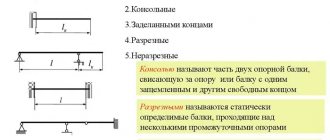
When calculating, the beam is perceived as a rigidly fixed rod, which is installed on two supports. If it is installed on three or more supports, calculating its deflection is more complex, and it is almost impossible to do it yourself. The main load is calculated as the sum of forces that act in the direction of the perpendicular section of the structure. A design diagram is required to determine the maximum deformation, which should not exceed the limit values. This will allow you to determine the optimal material of the required size, cross-section, flexibility and other indicators.
Types of beams
Beams made of strong and durable materials are used for the construction of various structures. Such structures may differ in length, shape and cross-section. Wooden and metal structures are most often used. For the deflection calculation scheme, the material of the element is of great importance. The specifics of calculating the deflection of a beam in this case will depend on the homogeneity and structure of its material.
Wooden
For the construction of private houses, cottages and other individual construction, wooden beams are most often used. Wooden structures that work in bending can be used for ceilings and floors.
Wooden floors
To calculate the maximum deflection, consider:
- Material. Different types of wood have different strength, hardness and flexibility.
- Cross-sectional shape and other geometric characteristics.
- Various types of load on the material.
The permissible deflection of the beam takes into account the maximum real deflection, as well as possible additional operational loads.
Coniferous wood structures
Steel
Metal beams have a complex or even composite cross-section and are most often made from several types of metal. When calculating such structures, it is necessary to take into account not only their rigidity, but also the strength of the connections.
Steel floors
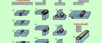
Metal structures are made by connecting several types of rolled metal, using the following types of connections:
- electric welding;
- rivets;
- bolts, screws and other types of threaded connections.
Steel beams are most often used for multi-story buildings and other types of construction where high structural strength is required. In this case, when using high-quality connections, a uniformly distributed load on the beam is guaranteed.
To calculate the beam for deflection, this video can help:
Beam deflections
As in the case of axial loading, in bending we will allow only small deformations. Let me remind you that to determine the tensile elongation, the original undeformed length is taken as the length, despite the fact that with uniform application of the load, with each increase in load, the initial length at each moment of time increases. The same is true in bending - we assume that the deflections of the beam do not affect its operation under load and the final load is applied to the undeformed beam. Based on this assumption, we will derive a formula for calculating deflections.
The existing beam theory is sufficient only to determine deflections for beams where there is a section of pure bending, where the radius of curvature is constant. It can be determined from the formula:
The maximum deflection in this case is determined as the height of a segment of a circle of radius r.
However, in the general case of bending, there is a transverse force Q, and, as a consequence of this, the bending moment M changes. And if the beam has a constant cross-section along its length, then the radius of curvature also changes.
The greater the moment in the section, the smaller the radius of curvature will be.
It is important to mention that in the general case of loading, a transverse force will act on the beam, which can also affect deflections. Although in long beams, where a sufficiently large bending moment has time to “run up”, its influence on deflections becomes extremely insignificant, in short beams the influence of shear deformations is usually taken into account, although taking them into account requires a more complex calculation technique. Within this course, we will limit ourselves to determining the deflections of beams only from bending moments acting on their sections.
In order to take into account the change in the bending moment and, consequently, the radii of curvature when determining the deflections of beams, it is necessary to obtain the dependence of the curvature of the curve (and, consequently, the moment M) on the x and y coordinates.
In the course of mathematical analysis, the derivation of the formula for the curvature of a plane curve is given:
For those interested, the derivation of this formula is given below.
Let there be a graph of the function y(x):
Let's mark a point on the graph m and draw a tangent to the graph at this point. We denote the angle between the tangent and the x-axis as α:
At a certain distance ∆s from point m on the graph, we denote point m1, at which we also draw a tangent to the graph. We denote the angle between the tangent and the x axis as α–∆α:
Increment by X – dx, increment by Y – dy:
From a physical point of view, curvature is:
We need to get rid of α and s by expressing them in terms of y and x coordinates:
By definition of derivative:
We get:
Let's consider the second factor:
ds can be transformed using the Pythagorean theorem:
Let's substitute into the final expression:
From a geometric point of view, the curvature is equal to:
The resulting equation connects the radius of curvature with the coordinates x (section of the beam) and y (its deflection).
Using the previously derived dependencies, we get:
This equation is called the differential equation of the elastic axis. It is nonlinear and using it to solve practical problems is extremely inconvenient. However, it can be noted that in relation to dy/dx (dy/dx is the slope of the tangent to the curve at any point), dy is very small for cases of small deflections relative to dx (small - relative to the length of the beam). And even more so, the square of this ratio tends to zero. In effect, this turns the denominator to one and greatly simplifies the expression:
It’s more convenient to write it like this:
To obtain deflections, this equation should be integrated twice over dx.
For clarity, let's look at an example. Let there be a simply supported beam with a uniformly distributed load:
In fact, such loading is true for every simply supported beam, because no one has canceled earth’s gravity. Well, we would like to determine the deflections of this beam, both the greatest and at any point we desire.
First, let's define the support reactions:
To determine deflections, we need to know the Young's modulus of the material E, the moment of inertia of the section Iz (it should not change along the length) and the dependence of the bending moment along the length. Let's say we have material properties and section characteristics. Now we need to get the dependence M(x).
Let's integrate over dx:
Here C is the constant of integration. It can be determined from the boundary conditions:
- At x=0, beam deflection y=0
- At x=L, beam deflection y=0
These boundary conditions cannot be used in the equation obtained above, since it is for rotation angles dy/dx, and the deflection equation y(x) is necessary. To obtain the deflection equation, let’s integrate over dx again:
Here D is another constant of integration. Since the resulting equation is a function of the beam deflections, the existing boundary conditions can be used.
First condition:
Second condition:
Total:
Equation for rotation angles:
Equation for deflections:
Let us solve the problem of finding the location of the greatest deflection and the magnitude of this deflection. At the location of the greatest deflection, the derivative of the deflection function will be equal to zero. Those. it is necessary to equate the resulting expression for dy/dx to zero:
The equation has three roots:
The second root for any beam length L turns out to be negative; the third root for any length L turns out to be greater than the length of the beam. Only the first root L/2 remains, which means the greatest deflection will be in the middle of the span, which is quite obvious for this example.
The location of the greatest deflection can also be determined by directly plotting the deflection function. This is much easier than the cubic equation solution.
To do this, let's consider a special case. Let be:
To plot a graph of the deflection function, we will use MS Excel. Before doing this, you need to double-check your calculations, since when solving cumbersome equations it is easy to make mistakes, which can lead to erroneous results.
After construction we get:
From the graph you can determine both the location of the greatest deflection and its magnitude, as well as deflections at any points of interest.
Maximum deflection:
As a second example, let's solve the following problem. It is necessary to find the deflections of a simply supported beam under the action of a distributed force q and a concentrated force P, if the beam is made of steel with an elastic modulus E = 200,000 MPa, and has a rectangular cross section with dimensions B and H (dimensions will be given later, the problem will be solved first in general).
It is necessary to find the deflections of a simply supported beam under the action of a distributed force q and a concentrated force P, if the beam is made of steel with an elastic modulus of 200,000 MPa and has a rectangular cross section with dimensions B and H.
There are two types of loads acting on the beam: distributed and concentrated. Let us assume that the sequence of application of these loads does not affect the operation of the beam, i.e. the result of the action of the sum of all forces is the same as the sum of the results of the action of all forces separately. This is the so-called principle of independent action of forces. It is quite consistent with what is happening in reality. Then this task is divided into three subtasks:
- Determination of deflections of a simply supported beam under a distributed load;
- Determination of deflections of a simply supported beam under concentrated load;
- Summation of deflections.
The first subtask has already been solved and the deflection equation has the following form:
Let's solve the second subtask:
The supports are replaced by their reactions to the beam:
From the static equations it turns out that:
Unlike the case of a distributed load, there are two sections in which the bending moment function changes its form.
First section:
Having the differential equation of the elastic axis
We get:
Let's integrate over dx and get the equation of rotation angles for the first section:
Let’s integrate over dx again and get the deflection equation for the first section:
Now let's look at the second section:
Let's integrate over dx and get the equation of rotation angles for the second section:
Let’s integrate over dx again and get the deflection equation for the second section:
The result is four unknown integration constants: C1, D1, C2, D2.
To determine them, the following boundary conditions are available:
- x=0, y=0 (first section)
- x=a, dy/dx (1) = dy/dx (2) (for both sections)
- x=a, y (1) = y (2) (for both sections)
- x=L, y=0 (second section)
To determine the relationship between the corresponding integration constants in both sections, we use the conditions that the angle of rotation and deflection at the point of application of the force P are equal for both sections:
To determine D, we use the condition x=0, y=0 for the equation of deflections of the first section:
To determine C, we use the condition x=L, y=0 for the equation of deflections of the second section:
In total we get:
At
To construct a deflection graph, let’s set the following values:
Moment of inertia of the section relative to the bending axis:
MS Excel was used to construct deflection graphs.
Beam deflections due to concentrated load:
Beam deflections from distributed load:
Total deflections:
Using the superposition principle to solve problems (finding deflections, etc.) is convenient only when you already have ready-made solutions for individual loads and all that remains is to summarize the result. Otherwise, in most cases it is easier to calculate the beam at once, taking into account all the loads.
Beam strength and rigidity
To ensure the strength, durability and safety of the structure, it is necessary to calculate the deflection value of the beams at the design stage of the structure. Therefore, it is extremely important to know the maximum deflection of the beam, the formula of which will help draw a conclusion about the likelihood of using a certain building structure.
Using a calculation scheme of rigidity allows you to determine the maximum changes in the geometry of the part. Calculating a structure using experimental formulas is not always effective. It is recommended to use additional coefficients to add the necessary safety margin. Not leaving an additional margin of safety is one of the main construction mistakes, which leads to the impossibility of using the building or even serious consequences.
There are two main methods for calculating strength and stiffness:
- Simple. When using this method, a magnification factor is applied.
- Accurate. This method includes the use of not only safety factors, but also additional calculations of the boundary state.
The last method is the most accurate and reliable, because it helps determine exactly what load the beam can withstand.
Calculation of beams for deflection
Ways to perform deflection calculations and tests
The reason why SNiPs establish such draconian restrictions is simple and obvious. The smaller the deformation, the greater the margin of strength and flexibility of the structure. For a deflection of less than 0.5%, the load-bearing element, beam or slab still retains elastic properties, which guarantees normal redistribution of forces and maintaining the integrity of the entire structure. As the deflection increases, the building frame bends, resists, but stands; when the permissible value is exceeded, the bonds break, and the structure loses its rigidity and load-bearing capacity like an avalanche.
There are several ways to calculate the deflection of a structure:
- Use an online software calculator, in which standard conditions are “hardwired”, and nothing more;
- Use ready-made reference data for various types and types of beams, for various supports of load patterns. It is only necessary to correctly identify the type and size of the beam and determine the desired deflection;
- Calculate the permissible deflection with your hands and your head; most designers do this, while controlling architectural and construction inspectors prefer the second method of calculation.
For your information!
To really understand why it is so important to know the magnitude of the deviation from the initial position, it is worth understanding that measuring the amount of deflection is the only accessible and reliable way to determine the condition of the beam in practice. By measuring how much the ceiling beam has sagged, you can determine with 99% certainty whether the structure is in disrepair or not.
Stiffness calculation
To calculate the bending strength of a beam, the formula is used:
Where:
M is the maximum moment that occurs in the beam;
Wn,min – moment of resistance of the section, which is a tabular value or is determined separately for each type of profile.
Ry is the design bending resistance of the steel. Depends on the type of steel.
γc is the operating condition coefficient, which is a tabular value.
Calculating the stiffness or deflection of a beam is quite simple, so even an inexperienced builder can perform the calculations. However, to accurately determine the maximum deflection, you must perform the following steps:
- Drawing up a design diagram of the object.
- Calculation of the dimensions of the beam and its section.
- Calculation of the maximum load that acts on the beam.
- Determination of the point of application of maximum load.
- Additionally, the beam can be tested for strength by maximum bending moment.
- Calculation of the stiffness value or maximum deflection of a beam.
To create a calculation scheme, you will need the following data:
- beam dimensions, length of consoles and span between them;
- cross-sectional size and shape;
- features of the load on the structure and its exact application;
- material and its properties.
If a two-support beam is being calculated, then one support is considered rigid, and the second is considered hinged.
Calculation of beams for deflection - formulas and instructions
In engineering and civil engineering sciences (strength of materials, structural mechanics, strength theory), a beam is understood as an element of a supporting structure that is susceptible primarily to bending loads and has various cross-sectional shapes.
- Basic provisions of calculation methods ↓
- Stiffness calculation algorithm ↓
- Determination of moments of inertia and section resistance ↓
- Determination of maximum load and deflection ↓
- Features of deflection calculations ↓
- Types of beams used in construction ↓
- Wooden ↓
- Steel ↓
Of course, in real construction, beam structures are also subject to other types of loading (wind load, vibration, alternating loading), however, the main calculation of horizontal, multi-supported and rigidly fixed beams is carried out under the action of either transverse or equivalent load reduced to it.
The calculation scheme considers the beam as a rigidly fixed rod or as a rod mounted on two supports. If there are 3 or more supports, the rod system is considered statically indeterminate and the calculation of deflection of both the entire structure and its individual elements becomes significantly more complicated.
In this case, the main load is considered as the sum of forces acting in the direction perpendicular to the section. The purpose of the deflection calculation is to determine the maximum deflection (deformation) which should not exceed the limit values and characterizes the rigidity of both an individual element (and the entire building structure associated with it.
Determination of maximum load and deflection
To accurately determine the deflection of a beam, it is best to use this formula:
Where:
q is a uniformly distributed load;
E – elastic modulus, which is a tabular value;
l – length;
I – moment of inertia of the section.
To calculate the maximum load, static and periodic loads must be taken into account. For example, if we are talking about a two-story structure, then the wooden beam will be constantly subject to the load from its weight, equipment, and people.
How to calculate auxiliary quantities
To obtain complete information about the values necessary to achieve the final goal of the calculations, you need to find out what the moment resistance of the section is (formula No. 2):
Wn(required) = M max / (Ry * Уc)
It is necessary to take into account the orientation of the beam section under consideration, since with a decrease in the moments of inertia, the rigidity of the beams decreases, which should not be allowed. To find out the maximum load value f that the beam can withstand, you need to calculate it using the following formula No. 3:
f = (5 / 384) * [(qn * L4) / (E * J)] £ [¦], where
- L – longitudinal dimension, in meters
- E – coefficient showing elasticity (it will be different for each material or alloy)
- J – moment of inertia along the section
- qn is a load, uniformly distributed, expressed in kg/m or N/m
The J indicator is calculated as follows:
J = b * h3 / 12
Designations:
- b – diameter of sections
- h – vertical section size
An example for sections measuring 15 by 20 centimeters:
J = 0.15 * (0.2)3 / 12 = 10,000 cm4 or 0.0001 m4
In addition to the indicated calculated or tabulated values, among the important factors that must be taken into account when determining the maximum loads are the following: static (which act constantly, regardless of variable external factors), periodic (the action of wind, vibration, shock).
Features of deflection calculations
Deflection calculations are required for any floors. It is extremely important to accurately calculate this indicator under significant external loads. In this case, it is not necessary to use complex formulas. If you use the appropriate coefficients, the calculations can be reduced to simple schemes:
- A rod that rests on one rigid and one hinged support and carries a concentrated load.
- A rod that rests on a rigid and hinged support and is subject to a distributed load.
- Options for loading a cantilever rod that is rigidly fixed.
- The effect of a complex load on a structure.
Using this method for calculating deflection allows you to ignore the material. Therefore, the calculations are not affected by the values of its main characteristics.