- Long products
August 28, 2019
1086
I-beam, as one of the varieties of shaped ferrous and non-ferrous metal products, is distinguished by a wide range of products. Therefore, during the design and further construction of structures using an I-beam, the right choice must be made. It must be based on correct calculations. Read our article on how to calculate the load on an I-beam.
Let us immediately note that for the calculations you will need formulas, tables and knowledge. And if they are not there, then it is better to entrust everything to an experienced and qualified engineer. Especially when it comes to an I-beam, which is used in loaded structures.
Both the quality of construction and the safety of operation of the facilities being built directly depend on this. All parameters must comply with current regulatory documents and ensure the design performance characteristics of the metal structure. This is due, first of all, to the scope of application of the I-beam, for example, as a floor element.
Calculation of the load on an I-beam - main selection parameters
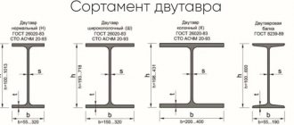
The operational characteristics of an I-beam directly depend on its cross-sectional profile and dimensions. This is largely due to the characteristics of the rolled metal itself. Let us recall that an I-beam is a type of metal product consisting of two shelves connected by a wall. The wall is often called the neck. This is why values such as:
- overall profile height (including neck length and thickness of two shelves);
- I-beam wall height;
- the total width of each shelf;
- the width of one part of the shelf from the neck to the edge (overhang);
- total length of the I-beam;
- neck (wall) thickness;
- thickness of the shelf with parallel edges;
- average thickness of rolled products with a slope of internal faces;
- radius of curvature of the transition from the flange to the neck (radius of conjugation, internal rounding);
- radius of curvature of the shelf (its edge).
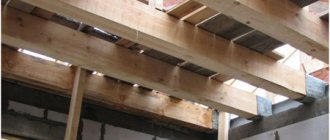
In addition, the characteristics of the object itself should be taken into account. Everything directly depends on the specific application of the I-beam. But basically this is such a parameter as the design load. In unloaded structures, an I-beam is used much less frequently. You also need to take the step into account. The step is a certain distance through which I-beams are installed parallel to each other. And the distance between the support points on which the I-beam is laid is also of great importance. This parameter is called span.
Methods for choosing the optimal profile section size
The most accurate option for selecting the number and type of I-profile is to carry out professional calculations. It is this method that is used when designing critical large-sized objects. When constructing small buildings, you can use an online calculator.
To approximately determine the size of the profile, you can use the table corresponding to the number of the I-beam and the maximum permissible load:
| Total load, kg/m2 | Span length | ||||||||
| 3 m at step, m | 4 m at step, m | 6 m at step, m | |||||||
| 1,0 | 1,1 | 1,2 | 1,0 | 1,1 | 1,2 | 1,0 | 1,1 | 1,2 | |
| 300 | 10 | 10 | 10 | 10 | 12 | 12 | 16 | 16 | 16 |
| 400 | 10 | 10 | 10 | 12 | 12 | 12 | 20 | 20 | 20 |
| 500 | 10 | 12 | 12 | 12 | 12 | 12 | 20 | 20 | 20 |
Source
The load calculation of an I-beam is carried out to determine the number from the assortment list when designing load-bearing structures of buildings and structures. The calculation is made according to formulas and tables, and the resulting parameters affect the design and construction process, as well as further operational characteristics of the structure.
Regulated values on axes
All calculations are performed based on reference values of several important parameters. Let us briefly outline the main ones. Let's start with the moment of inertia. I'm interested in its value relative to a pair of central axes. The table value is determined by the assortment table specified in GOSTs. For example, in Russia, GOST R 57837-2017 is in force for I-beams with parallel fracture edges. In other CIS countries there is GOST 8239-89 for rolled products with sloped internal edges. There are a number of other regulatory documents.
Sometimes it is necessary to take into account the centrifugal moment. It is not included in the tables. Because by default the centrifugal moment is 0 on both axes. The parameters that determine inertia are used:
- radius relative to one of the central axes;
- static half-section moment about the axis;
- axial moment.
The design resistance parameter, denoted Ry, has a great influence on the calculations. This is also a tabular parameter; it depends directly on the grade of steel used in the production of the I-beam. For example, carbon steel grade C235 has a design resistance of 230 MPa. For other steel grades this parameter will be different.
The next important parameter is the elastic modulus. It all depends on the characteristics of the material from which the I-beam is made. We forgot to note, but the calculated resistance also depends on this characteristic. In the classical sense - shaped black metal products. This means that the elastic modulus E is taken for steel. In this case it is equal to 200000 MPa. But maybe, for example, according to GOST 13621-90 non-ferrous rolled metal. Plus different types of wood. There the moment of inertia will be different. Such features must be taken into account when calculating the load on an I-beam.
Depending on the structural features of the object, sometimes it becomes necessary to use other design parameters. As a rule, table values are taken.
Calculation of load on I-beam and load-bearing capacity
Special tables have been developed. In them, the I-beam number is selected based on three main parameters:
- expected load, kg/m.p. (kilogram per linear meter);
- the size of the span, noted above, m (meters);
- pitch with which the I-beam is laid, m (meters).
The number refers to the profile height in centimeters (from 10 to 100 according to the current regulatory framework).
The estimated load is calculated based on the bearing capacity of the products. It is important to take into account the I-beam production technology. Let us remind you that it can be hot-rolled, welded, riveted (if metal is used). Hot rolled is obtained by rolling a workpiece, welded by welding the shelves to the wall. A riveted beam uses rivets to connect elements. So if this is a welded I-beam. In this case, when calculating the current load-bearing capacity, it is necessary to add about 30% additionally for strength.
The design load itself is determined as follows. Calculate such a parameter as the pressure on the structure. In this case, the weight of the structure is taken into account in terms of one linear meter of I-beam. Then the resulting value is multiplied by the reliability coefficient (directly depends on the type of I-beam and the GOST used). After this, based on the obtained value from the table, the moment of resistance is selected. And based on the moment of resistance, the profile number is determined based on the current assortment. We recommend playing it safe and choosing two numbers higher.
Important point. The load-bearing capacity of an I-beam is established only and exclusively on the basis of the design load. You cannot use only one standard load. It was made without taking into account the specifics of the metal structures being erected, their structural features and operational parameters.
And one last thing. The load-bearing capacity is taken into account when calculating bending loads in an I-beam.
Calculation of metal beams online (calculator).
1. Collection of loads
Before starting the calculation of a steel beam, it is necessary to collect the load acting on the metal beam. Depending on the duration of action, loads are divided into permanent and temporary.
Constant loads include:
- own weight of the metal beam;
- own weight of the floor, etc.;
Temporary loads include:
- long-term load (payload, taken depending on the purpose of the building);
- short-term load (snow load, taken depending on the geographical location of the building);
- special load (seismic, explosive, etc. Not taken into account within this calculator);
Loads on a beam are divided into two types: design and standard. Design loads are used to calculate the beam for strength and stability (1st limit state). Standard loads are established by standards and are used to calculate beams for deflection (2nd limit state). Design loads are determined by multiplying the standard load by the reliability load factor. Within the framework of this calculator, the design load is used to determine the deflection of the beam to reserve.
The general calculation of metal structures can be read on our website.
Loads can be collected on our website.
After you have collected the surface load on the floor, measured in kg/m2, you need to calculate how much of this surface load the beam takes on. To do this, you need to multiply the surface load by the pitch of the beams (the so-called load strip).
For example: We calculated that the total load was Qsurface = 500 kg/m2, and the beam spacing was 2.5 m. Then the distributed load on the metal beam will be: Qdistributed = 500 kg/m2 * 2.5 m = 1250 kg/m. This load is entered into the calculator
2. Constructing diagrams
Next, a diagram of moments and transverse forces is constructed. The diagram depends on the loading pattern of the beam and the type of beam support. The diagram is constructed according to the rules of structural mechanics. For the most frequently used loading and support schemes, there are ready-made tables with derived formulas for diagrams and deflections.
3. Calculation of strength and deflection
After constructing the diagrams, a calculation is made for strength (1st limit state) and deflection (2nd limit state). In order to select a beam based on strength, it is necessary to find the required moment of inertia Wtr and select a suitable metal profile from the assortment table. The vertical maximum deflection fult is taken according to table 19 from SNiP 2.01.07-85* (Loads and impacts). Point 2.a depending on the span. For example, the maximum deflection is fult=L/200 with a span of L=6m. means that the calculator will select a section of a rolled profile (I-beam, channel or two channels in a box), the maximum deflection of which will not exceed fult=6m/200=0.03m=30mm. To select a metal profile based on deflection, find the required moment of inertia Itr, which is obtained from the formula for finding the maximum deflection. And also a suitable metal profile is selected from the assortment table.
4. Selection of a metal beam from the assortment table
From two selection results (limit state 1 and 2), a metal profile with a large section number is selected.
Strength and deflection of an I-beam
The strength of the I-beam is determined taking into account standard stresses. During this, so-called diagrams of internal forces are constructed, in addition to stresses, and also displacements. They are based on such parameters as the influence of forces in the longitudinal and transverse planes, moments (meaning bending and torsional).
As noted above, the characteristics of the material are of great importance. If we are talking about black rolled steel, then the fundamental criterion is the steel grade. If it is wood, then its species. It is the characteristics of the material that are taken into account when calculating strength. It is better to choose materials with increased strength. This fully applies to steel grades. Keep in mind that the stronger the material, the smaller the dimensions of the I-beam. This state of affairs means that the load on the structure as a whole is reduced. The permissible pressure value becomes smaller. And one last thing. An experienced and qualified engineer always uses several methods to determine the strength of a material. After all, it is necessary to distribute the applied force along the axes. Then set the maximum moments around each of the axes. At the final stage, the values obtained by calculation are compared.
The deflection of the I-beam is calculated based on such parameters as:
- load in kg/m (kilograms per meter), both the design and standard load are taken;
- span (distance between reference points in m (meters);
- design resistance (measured in MPa (megapascals)).
Important point. The maximum deflection value is determined based on the structural purpose of the I-beam. So, if an I-beam is used in interfloor ceilings, then the deflection is less than 1/250. And if these are roofing structures and lintels, then 1/200. Other structural elements will have correspondingly different values. The deflection can be reduced only by changing the initial parameters. That is, use lightweight structures and reduce the load. The second option is to reduce the distance between two support points, for example, by using an additional (intermediate) one.
Is it possible to do without calculating the deflection?
The answer options depend on the characteristics of the object and its functional purpose. For example, if it is a small, single-level structure, especially for economic purposes, then there are options. The first is to calculate the deflection of the I-beam, the second is to calculate the load-bearing capacity of the structures being built. But a lot depends on the finishing materials used for finishing and their weight. Therefore, it is better to calculate the deflection even for individual construction of private households and outbuildings.
It is important to understand the fact that deflection is also formed in the corners of rotation. Much depends on the design, its:
- functional purpose;
- main dimensions;
- characteristics of the materials used, the same grade of steel, as a special case;
- physical parameters.
There are many formulas for calculating deflection. There is no point in dwelling on them in detail within the framework of our article. Let us just note that much depends on the type of load. It's about the direction of its action. The thing is that the I-beam can be affected by multidirectional loads. As a rule, this is a downward deflection, but there are others. Moreover, sometimes it is a combination of multidirectional loads. Then the deflection is determined for each of them separately.
Various methods for calculating deflection can be used, for example, using the method of initial parameters.
Calculating the load on an I-beam is a key parameter for choosing this type of product. Any error in calculations or ignoring them can lead to tragic consequences. Therefore, the issue must be approached responsibly, and the choice must be made with reserve. When all the calculations have been made and double-checked, please contact us. We offer a wide range of I-beams. We’ll help you choose exactly the I-beam you need.
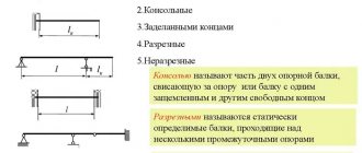
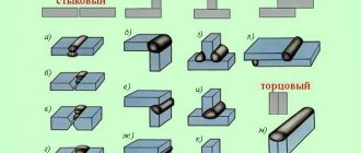
H-profile fastening schemes
For the convenience of calculating what maximum load an I-beam can withstand, all options for using the profile were reduced to several standard schemes. The schemes differ in the method of attaching the I-beam and applying the load:
- On two hinged supports located at the ends of the profile. The first option is with a uniformly distributed load, the second is with a concentrated force in the center.
- Console. With uniform or concentrated effort.
- On two articulated supports with an extension, the beam is loaded evenly along its entire length or concentrated.
- Beam on two rigidly clamped supports with different types of forces.
After choosing a formal scheme, the loads that the beam will experience are collected.