Crane beam device
A beam crane is a technical device designed to lift and move cargo. According to the description given in the Brief Polytechnic Dictionary, a beam crane is a lightweight single-girder overhead crane with a manual or electric drive. A distinctive feature of the device is the presence of two support points, and not one, like most other lifting mechanisms. The crane beam supports can be fixed, rigidly fixed structures, or movable supports made like bridge supports. Most often these are rolled metal products mounted on the load-bearing walls of the room in which the mechanism is located.
One of the supports of a homemade crane beam, made of two corners welded together, attached to the wall of the garage.
The crane beam consists of: load-bearing supports, the working beam itself, a slide for moving along the supports, a movable carriage, any lifting mechanism with a rotating hook (hoist, winch, hoist).
Types of overhead crane control
Manual control
— by manual drive, namely a drive chain, the crane-beam moves along guides.
In the case of electrical control from the floor via a remote control
or
radio control system
, the design of the crane becomes somewhat more complicated. For control from the floor, special cable routes are led to an electrical cabinet mounted on the end beam of the crane, and from the cabinet they are already distributed to the electrical components of the crane. Movement and lifting/lowering of the load is carried out by pressing buttons or moving the joystick on the remote control, depending on the configuration of the crane.
To install radio control, it is necessary to install a control unit and a receiver/transmitter to the crane-beam electric drive system. The signal received at a distance from the crane enters the radio receiver, is processed by the radio control unit and carries out this command using electric drives.
Tools and materials
To create this mechanism in the garage, you will need the following tools and materials.
- Rolled metal – angle, channel, I-beam.
- Bearings of different sizes.
- Welding machine with electrodes.
- "Bulgarian".
- Drill or drilling machine.
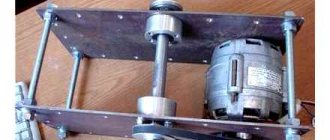
- Actuating mechanism – hoist, hoist.
- Marking tool (ruler or caliper, tape measure, chalk or marker)
- Bolts, washers, nuts.
The length of the rolled metal is selected based on the size of the room, and its grade is determined from the calculations given below. Bearings can be taken in any suitable size. The quantity is selected according to the principle: 4 pcs. for one slide, 4 pcs. – for the second, plus 4 pcs. for the carriage (lift body). Total: 12 pieces. The bearings for the slide must be the same size; the carriage can be fitted with bearings of the same size or one size larger or smaller. Bolts for fastening must be selected with large metric threads. The actuator is selected according to its maximum load capacity and design loads.
Carrying out calculations
In order to make a crane beam in the garage with your own hands, you need to calculate the dimensions of the structure and the grade of rolled metal according to the load capacity. Such calculations are performed using special online calculators, which allow you to select the necessary materials with sufficient accuracy for handicraft production. These calculators require you to enter the dimensions of the structure and the maximum allowable weight that is expected to be lifted and moved. Then you need to make a working drawing and you can start working.
It is best to make the working beam of the mechanism from equal-flange I-roll, because when using welded corners it is very difficult to achieve uniformity of the rolling surface. Uneven rolling surfaces will lead to underloading of some bearings and overloading of others. The working beam slide can be made from a section of channel, the length of which will be equal to the width of the I-beam flange of the working beam. The size should allow it to slide freely along the span beam supports.
Here the bolts are used as racks for fastening the support bearings.
Lift carriage
The lift carriage is made from a section of channel, the length of which is equal to the length of the supporting part of this mechanism. The size of the channel is assumed to be equal to the width of the I-beam flange.
It is necessary to clarify that during the manufacture of the carriage, the support bearings on different sides of the carriage are not installed opposite each other, but “in a running motion.” This was done in order to distribute the load on the I-beam shelf as evenly as possible.
The carriage can be made from two metal plates of any shape - triangular, square, truncated cone. Support bearings are installed on the inner sides of both plates, and underneath the plates are combined into a single unit using bolts or welding. In the lower part, a rod or insert is installed between the plates, to which the fastening hook of the actuator clings. This type is used when using lifting devices that are attached to the lift body with a hook.
If it is envisaged that the lift will be fastened using a support plate, then instead of a bolt, a plate with holes for mounting bolts is attached under the hook. They fix the actuator on the carriage. For some types of carriages, especially for industrial use, an additional motor is mounted on the support platform, which, by rotating the support bearings, moves the lift body along the working beam. As a rule, an electric motor with a low speed is installed as such a motor, the power to which is supplied by a flexible cable on sliding suspensions. In conditions of handicraft production, when the crane beam is used infrequently and the volume of work is small, the installation of such a complex structure is hardly justified.
The self-propelled carriage is controlled using a multipolar switch, which further complicates the design. In a garage, when making a crane beam yourself, a simple non-self-propelled carriage, which moves along the beam manually using a drive cable or chain, is quite sufficient.
Some craftsmen make female lift bodies that are installed on the top flange of the I-beam, rather than on the bottom. In this case, the support bearings are installed inside the lift body, and the lift itself is assembled from two identical parts. The device becomes more voluminous, but its reliability increases. For better sliding along the beam, additional bearings are installed horizontally on the lift body, two on each side. This is done so that the lift body does not touch the plane of the beam.
Here the lifting mechanism is fastened with a fastening hook using the lowest bolt.
A homemade lift body designed to use a lifting device attached with a mounting hook to the bottom plate.
Installation of lifting mechanism
After assembling the lift body and its trial installation on the beam, it is removed again, and holes are drilled according to the size of the factory holes in the mechanism platform. The lifting mechanism is installed on the carriage, then the assembled device is installed on the working beam. Installation of a lifting device with a mounting hook is even simpler: it is simply hooked with the hook onto the carriage that is fully assembled and installed on the beam supports.
Installation
There are the following methods for installing a single-girder overhead crane:
- Element-by-element. The bridge mechanism units are assembled on the crane tracks.
- Enlarged assembly. Large blocks of elements are assembled on the ground and raised to a fixed height. This assembly option is used for electrical equipment.
- Full block. This installation method is carried out on the floor. The bridge structure is completely assembled, after which it is installed.
Before dismantling the overhead crane, it is necessary to determine whether it can be recycled. If the device is to be disposed of, it is necessary to remove the crane beam, power supply cables, electric motor and cables. Elements made of metal must be sent for scrap.
If the device is not to be disposed of, it must be moved to a non-working area and the running gears must be disconnected. For reassembly, the single girder crane must be moved back to the job site.
Transportation of the disassembled overhead crane is carried out using railway platforms. Large devices are transported in 2–3 sections. Frames and lifting elements are transported separately. If the device has a low load capacity, it can be transported assembled.
Crane beam assembly
The assembly of a homemade crane beam occurs as follows:
- the device supports are attached to the wall or ceiling;
- a carriage is installed on the prepared working beam;
- if the actuator is mounted on a support platform, then it is installed on the lift body;
- the assembled work beam is lifted and placed on supports;
- check smooth operation and adjust operating parameters.
In the case of attaching the lifting mechanism to the support platform, the assembly is complete.
An assembled crane beam with a lift, which is fixed with a fastening hook by the lower bolt.
Making a simple lifting device yourself in your garage is not that difficult. It is necessary to carry out the calculations correctly and boldly get to work. At the same time, you need to remember about safety precautions - any lifting device is potentially dangerous. For example, according to the existing requirements of Rostechnadzor, the presence of more than 30% broken threads in a steel rope (cable) makes such a cable unsuitable for further use.
Main differences and scope of application
In addition to design differences, both types have a number of features that determine the method of their installation. The crane runway of the beam crane does not provide for the installation of additional supports. The mechanism can be mounted directly to the ceiling in accordance with safety requirements.
Beam-type devices are used in small workshops and covered warehouses with limited space. Bridge equipment is installed in the workshops of steel mills, in ports, and in large-scale production. In open areas, a gantry-type overhead crane is used on special mobile supports.