Calculation of floor beams
The calculation of wooden floor beams in a house is carried out according to the second limit state (by deflections). Relative deflection 1/250 (according to SNiP “Loads and Impacts”). In practice, this means that the floor beam, when loaded with a uniformly distributed load of 400 kg/m2 or 250, 200 kg/m2 in some cases, will bend in the center by an amount equal to L/250, where L is the estimated length of the beam (distance in light between supports).
For example, if the design length of the beam is 6 m (6000 mm), then the deflection in the center at maximum load will be 6000/250 = 24 mm. Those. in this example, 24 mm is the maximum permissible deflection of the beam, at which comfortable operation of the ceiling is possible - there will be no vibrations, creaks, or “trampoline” feeling.
Below are tables of the relationship between the type of I-beams, the pitch of their installation, the design load and the maximum span under which these conditions are met.
Get price list
Go to the prices section
More about beams
Notes:
- Beams of the W series are manufactured in lengths of 6 meters. The maximum span that they cover is 5.8 m (with a minimum support of 100 mm on both sides)
- Beams of the L series are manufactured in lengths up to 13.5 meters.
- Recommended steps are 0.4 and 0.6 m for interfloor ceilings; 0.6 and 0.8 for attic floors.
- The maximum span is the “clear” distance between adjacent supports.
- Beam spacing is the center-to-center distance of two adjacent beams.
Calculation table for interfloor and basement beams
Load calculation of 400 kg/m2 for wooden floors
| Beam height, mm | Type of beams / pitch of beams | Maximum spans, m | |||
| 0,3 | 0,4 | 0,5 | 0,6 | ||
| 240 | Beam ICJ-240W | 4,95 | 4,50 | 4,16 | 3,93 |
| 300 | Beam ICJ-300W | 5,80 | 5,35 | 4,96 | 4,70 |
| 360 | Beam ICJ-360W | 5,80 | 5,80 | 5,75 | 5,38 |
| 400 | Beam ICJ-400W | 5,80 | 5,80 | 5,80 | 5,80 |
| 240 | Beam ICJ-240L | 5,45 | 4,95 | 4,55 | 4,30 |
| 240 | Beam ICJ-240L with flange 89 mm | 6,05 | 5,50 | 5,10 | 4,80 |
| 300 | Beam ICJ-300L | 6,50 | 5,90 | 5,45 | 5,15 |
| 300 | Beam ICJ-300L with flange 89 mm | 7,20 | 6,55 | 6,10 | 5,75 |
| 360 | Beam ICJ-360L | 7,45 | 6,75 | 6,30 | 5,90 |
| 360 | Beam ICJ-360L with flange 89 mm | 8,30 | 7,50 | 7,00 | 6,60 |
| 400 | Beam ICJ-400L | 8,10 | 7,35 | 6,80 | 6,40 |
| 400 | Beam ICJ-400L with flange 89 mm | 9,00 | 8,15 | 7,50 | 7,10 |
| 460 | Beam ICJ-460L | 9,00 | 8,15 | 7,50 | 7,10 |
| 460 | Beam ICJ-460L with flange 89 mm | 10,00 | 9,05 | 8,40 | 7,90 |
| 500 | Beam ICJ-500L | 9,60 | 8,70 | 8,05 | 7,60 |
| 500 | Beam ICJ-500L with flange 89 mm | 10,60 | 9,60 | 8,95 | 8,40 |
| 600 | Beam ICJ-600L | 11,00 | 9,95 | 9,25 | 8,70 |
| 600 | Beam ICJ-600L with flange 89 mm | 12,00 | 11,00 | 10,20 | 9,60 |
Types of interfloor ceilings
According to their purpose, floors are divided into:
- interfloor;
- attics;
- basement (basement).
Features of their design include permissible loads and vapor and heat insulation. If the attic is not intended for living or storing massive objects, variable loads when calculating deflection can be reduced to 50–100 kg/m2.
Thermal insulation between two residential floors may seem unnecessary, but sound insulation is a desirable parameter for most, and this is achieved, as a rule, with the same materials. It should be taken into account that attic and basement floors require a thicker layer of thermal insulation material. Film material for vapor barrier in the attic floor should be located under the insulation layer, and in the basement - above it. To prevent the occurrence of dampness and fungal damage to structures, all rooms must be equipped with ventilation.
Flooring options: 1 - plank board; 2 - vapor barrier; 3 - thermal insulation; 4 - sparse flooring; 5 - boards; 6 - flooring
The design of the floors can also be different:
- with open and hidden beams;
- with different types of load-bearing beams;
- with different filling and cladding materials.
Hidden beams are sewn on both sides and are not visible. Open - protrude from the ceiling and serve as decorative elements.
The figure below shows what the structure of the ceiling of an attic floor with a panel roll and a lining of boards can be.
a - with a shield roll; b - with boarding; 1 - plank floor; 2 - polyethylene film; 3 - insulation; 4 - vapor barrier; 5 - wooden beams; 6 — cranial bars; 7 — shield roll; 8 - finishing; 9 - boarding of boards
Calculation table for attic floor beams that are not in use
Calculation for a load of 200 kg/m2 without load on wooden floors from the rafter system
| Beam height, mm | Type of beams / pitch of beams | Maximum spans, m | ||||
| 0,4 | 0,5 | 0,6 | 0,7 | 0,8 | ||
| 240 | Beam ICJ-240W | 5,65 | 5,52 | 4,95 | 4,68 | 4,50 |
| 300 | Beam ICJ-300W | 5,80 | 5,80 | 5,80 | 5,60 | 5,35 |
| 360 | Beam ICJ-360W | 5,80 | 5,80 | 5,80 | 5,80 | 5,80 |
| 400 | Beam ICJ-400W | 5,80 | 5,80 | 5,80 | 5,80 | 5,80 |
| 240 | Beam ICJ-240L | 6,20 | 5,80 | 5,45 | 5,15 | 4,95 |
| 240 | Beam ICJ-240L with flange 89 mm | 6,90 | 6,45 | 6,05 | 5,75 | 5,50 |
| 300 | Beam ICJ-300L | 7,40 | 6,90 | 6,50 | 6,15 | 5,90 |
| 300 | Beam ICJ-300L with flange 89 mm | 8,25 | 7,70 | 7,20 | 6,90 | 6,60 |
| 360 | Beam ICJ-360L | 8,50 | 7,90 | 7,50 | 7,10 | 6,80 |
| 360 | Beam ICJ-360L with flange 89 mm | 9,45 | 8,80 | 8,30 | 7,90 | 7,55 |
| 400 | Beam ICJ-400L | 9,25 | 8,60 | 8,10 | 7,70 | 7,40 |
| 400 | Beam ICJ-400L with flange 89 mm | 10,25 | 9,55 | 9,00 | 8,50 | 8,15 |
| 460 | Beam ICJ-460L | 10,25 | 9,55 | 9,00 | 8,50 | 8,15 |
| 460 | Beam ICJ-460L with flange 89 mm | 11,40 | 10,60 | 10,00 | 9,50 | 9,05 |
| 500 | Beam ICJ-500L | 11,00 | 10,15 | 9,55 | 9,10 | 8,65 |
| 500 | Beam ICJ-500L with flange 89 mm | 12,15 | 11,30 | 10,60 | 10,05 | 9,65 |
| 600 | Beam ICJ-600L | 12,50 | 11,65 | 11,00 | 10,40 | 9,95 |
| 600 | Beam ICJ-600L with flange 89 mm | 13,30 | 12,90 | 12,15 | 11,55 | 11,05 |
Requirements for interfloor ceilings
Interfloor ceilings must withstand constant and variable loads, that is, in addition to their own weight, they must withstand the weight of furniture and people.
They must be sufficiently rigid and not allow the maximum deflection to be exceeded, and provide sufficient noise and heat insulation. Before work, we advise you to familiarize yourself with the materials set out in SNiP II-25–80 (SP 64.13330.2011), there is a lot of useful information there.
Specific loads from furniture and people for residential premises are accepted in accordance with the standards. However, if you plan to install something massive, for example, a 1000 liter aquarium or a fireplace made of natural stone, this must be taken into account.
The stiffness of beams is determined by calculation and is expressed in permissible bending per span length. The permissible bend depends on the type of floor and covering material. The main maximum deflections determined by SNiP are given in Table 1.
Table 1
| Structural elements | Limit deflections in fractions of span, no more |
| 1. Beams between floors | 1/250 |
| 2. Attic floor beams | 1/200 |
| 3. Coverings (except valleys): | |
| a) purlins, rafter legs | 1/200 |
| b) cantilever beams | 1/150 |
| c) trusses, laminated beams (except for cantilever beams) | 1/300 |
| d) slabs | 1/250 |
| e) lathing, flooring | 1/150 |
| 4. Load-bearing elements of valleys | 1/400 |
| 5. Panels and half-timbered elements | 1/250 |
| Notes: 1. If there is plaster, the deflection of the floor elements only from long-term temporary load should not exceed 1/350 of the span. 2. In the presence of a construction rise, the maximum deflection of glued beams can be increased to 1/200 of the span. |
Please note that floor coverings in the form of ceramic tiles or concrete screeds, which are prone to cracking, may further tighten the requirements for permissible deflection, especially with sufficiently long spans.
To reduce the load on the beams, if possible, they should be placed parallel to short walls, with the same spacing. The maximum span length when covered with wooden beams is 6 m.
Calculation table for attic floor beams that are not in use
Calculation for a load of 250 kg/m2 with a load on the floor from the rafter system
| Beam height, mm | Type of beams / pitch of beams | Maximum spans, m | ||||
| 0,4 | 0,5 | 0,6 | 0,7 | 0,8 | ||
| 240 | Beam ICJ-240W | 5,25 | 4,95 | 4,60 | 4,35 | 4,15 |
| 300 | Beam ICJ-300W | 5,80 | 5,80 | 5,50 | 5,20 | 4,95 |
| 360 | Beam ICJ-360W | 5,80 | 5,80 | 5,80 | 5,80 | 5,70 |
| 400 | Beam ICJ-400W | 5,80 | 5,80 | 5,80 | 5,80 | 5,80 |
| 240 | Beam ICJ-240L | 5,77 | 5,36 | 5,04 | 4,79 | 4,58 |
| 240 | Beam ICJ-240L with flange 89 mm | 6,43 | 5,97 | 5,61 | 5,33 | 5,10 |
| 300 | Beam ICJ-300L | 6,88 | 6,39 | 6,01 | 5,71 | 5,46 |
| 300 | Beam ICJ-300L with flange 89 mm | 7,68 | 7,13 | 6,70 | 6,37 | 6,09 |
| 360 | Beam ICJ-360L | 7,92 | 7,35 | 6,92 | 6,57 | 6,28 |
| 360 | Beam ICJ-360L with flange 89 mm | 8,80 | 8,17 | 7,69 | 7,31 | 6,99 |
| 400 | Beam ICJ-400L | 8,58 | 7,97 | 7,50 | 7,12 | 6,81 |
| 400 | Beam ICJ-400L with flange 89 mm | 9,54 | 8,85 | 8,33 | 7,91 | 7,57 |
| 460 | Beam ICJ-460L | 9,54 | 8,85 | 8,33 | 7,91 | 7,57 |
| 460 | Beam ICJ-460L with flange 89 mm | 10,59 | 9,83 | 9,25 | 8,79 | 8,40 |
| 500 | Beam ICJ-500L | 10,16 | 9,43 | 8,87 | 8,43 | 8,06 |
| 500 | Beam ICJ-500L with flange 89 mm | 11,27 | 10,46 | 9,84 | 9,35 | 8,94 |
| 600 | Beam ICJ-600L | 11,64 | 10,81 | 10,17 | 9,66 | 9,24 |
| 600 | Beam ICJ-600L with flange 89 mm | 12,89 | 11,97 | 11,26 | 10,70 | 10,23 |
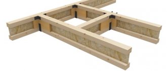
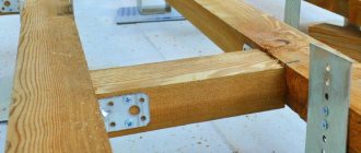
Types of fastenings and connections of wooden beams
Depending on the design and material of the load-bearing walls, wooden beams are attached:
- into the nests provided in the brick or block masonry, deepening the beam or log at least 150 mm, and the board at least 100 mm;
- on the shelves (ledges) provided in the brick or block masonry. It is used if the wall thickness of the second floor is less than the first;
- into cut grooves in log walls to a depth of at least 70 mm;
- to the beam of the upper frame of the frame house;
- to metal support brackets fixed to the walls.
1 - support on a brick wall; 2 - solution; 3 - anchor; 4 — roofing felt insulation; 5 - wooden beam; 6 — support on a wooden wall; 7 - bolt
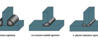
If the length of the beam is not enough, you can lengthen it by connecting (joining) along the length using one of the known methods using wooden pins and wood glue. When choosing the type of connection, be guided by the direction of application of the load. It is advisable to reinforce the spliced beams with metal overlays.
a - compression; b - stretching; c - bend
Calculation of beams for deflection - formulas and instructions
In engineering and civil engineering sciences (strength of materials, structural mechanics, strength theory), a beam is understood as an element of a supporting structure that is susceptible primarily to bending loads and has various cross-sectional shapes.
- Basic provisions of calculation methods ↓
- Stiffness calculation algorithm ↓
- Determination of moments of inertia and section resistance ↓
- Determination of maximum load and deflection ↓
- Features of deflection calculations ↓
- Types of beams used in construction ↓
- Wooden ↓
- Steel ↓
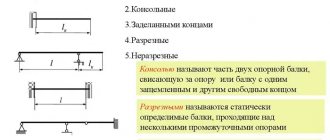
Of course, in real construction, beam structures are also subject to other types of loading (wind load, vibration, alternating loading), however, the main calculation of horizontal, multi-supported and rigidly fixed beams is carried out under the action of either transverse or equivalent load reduced to it.
The calculation scheme considers the beam as a rigidly fixed rod or as a rod mounted on two supports. If there are 3 or more supports, the rod system is considered statically indeterminate and the calculation of deflection of both the entire structure and its individual elements becomes significantly more complicated.
In this case, the main load is considered as the sum of forces acting in the direction perpendicular to the section. The purpose of the deflection calculation is to determine the maximum deflection (deformation) which should not exceed the limit values and characterizes the rigidity of both an individual element (and the entire building structure associated with it.
Basic provisions of calculation methods
Modern construction methods for calculating rod (beam) structures for strength and rigidity make it possible, already at the design stage, to determine the value of the deflection and make a conclusion about the possibility of operating the building structure.
Calculation of rigidity allows us to resolve the issue of the greatest deformations that can occur in a building structure under the complex action of various types of loads.
Modern calculation methods, carried out using specialized calculations on electronic computers, or performed using a calculator, make it possible to determine the rigidity and strength of the research object.
Despite the formalization of calculation methods, which involve the use of empirical formulas, and the effect of real loads is taken into account by introducing correction factors (safety factors), a comprehensive calculation quite fully and adequately assesses the operational reliability of a constructed structure or a manufactured element of a machine.
Despite the separateness of strength calculations and determination of structural rigidity, both methods are interrelated, and the concepts of “rigidity” and “strength” are inseparable. However, in machine parts, the main destruction of an object occurs due to loss of strength, while structural mechanics objects are often unsuitable for further use due to significant plastic deformations, which indicate low rigidity of structural elements or the object as a whole.
Today, in the disciplines “Strength of Materials”, “Structural Mechanics” and “Machine Parts”, two methods of calculating strength and stiffness are accepted:
- Simplified (formal), during which aggregated coefficients are used in calculations.
- Refined , where not only safety factors are used, but also contraction is calculated based on limit states.
Stiffness calculation algorithm
Formula for determining the bending strength of a beam
Where:
- M – maximum moment occurring in the beam (found from the moment diagram);
- Wn,min – moment of resistance of the section (found from the table or calculated for a given profile), a section usually has 2 moments of resistance of the section, Wx is used in calculations if the load is perpendicular to the x-x axis of the profile or Wy if the load is perpendicular to the yy axis;
- Ry – design resistance of steel in bending (set in accordance with the choice of steel);
- γc – operating conditions coefficient (this coefficient can be found in Table 1 SP 16.13330.2011;
The algorithm for calculating rigidity (determining the amount of deflection) is quite formalized and is not difficult to master.
In order to determine the deflection of the beam, it is necessary to perform the following steps in the sequence below:
- Draw up a design diagram of the research object.
- Determine the dimensional characteristics of the beam and design sections.
- Calculate the maximum load acting on the beam, determining the point of its application.
- If necessary , the beam (in the design scheme it will be replaced by a weightless rod) is additionally checked for strength by the maximum bending moment.
- The value of the maximum deflection is determined , which characterizes the rigidity of the beam.
To draw up a design diagram of a beam, you need to know:
- Geometric dimensions of the beam , including the span between the supports, and if there are consoles, their length.
- Geometric shape and cross-sectional dimensions.
- The nature of the load and the point of their application.
- Beam material and its physical and mechanical characteristics.
In the simplest calculation of two-support beams, one support is considered rigid, and the second is hinged.
Determination of moments of inertia and section resistance
The geometric characteristics that are necessary when performing strength and stiffness calculations include the moment of inertia of the section (J) and the moment of resistance (W). To calculate their values, there are special calculation formulas.
Section modulus formula
Determination of maximum load and deflection
Formula for determining deflection
Where:
- q – uniformly distributed load, expressed in kg/m (N/m);
- l – beam length in meters;
- E – elastic modulus (for steel equal to 200-210 GPa);
- I – moment of inertia of the section.
When determining the maximum load, it is necessary to take into account a fairly significant number of factors acting both constantly (static loads) and periodically (wind, vibration shock load).
In a one-story house, the wooden beam of the ceiling will be subject to constant weight forces from its own weight, partitions located on the second floor, furniture, occupants, and so on.
Features of deflection calculations
Of course, the calculation of floor elements for deflection is carried out for all cases and is mandatory in the presence of a significant level of external loads.
Today, all calculations of the deflection value are quite formalized and all complex real loads are reduced to the following simple calculation schemes:
- A rod resting on a fixed and hinged support, perceiving a concentrated load (the case is discussed above).
- A rod resting on a fixed and hinged rod on which a distributed load acts.
- Various loading options for a rigidly fixed cantilever rod.
- The action of a complex load on a design object - distributed, concentrated, bending moment.
About wooden floor beams
In construction, beams of rectangular, circular or partially circular cross-section are used. The most reliable are rectangular lumber, and the rest are used in conditions where there is no timber or for reasons of economy, if such materials are available on the farm. Glued wood materials are even more durable. Beams made of laminated veneer lumber or I-beams can be installed for spans of up to 12 m.
The most inexpensive and popular type of wood is pine, but other coniferous species are also used - larch, spruce. Spruce is used to make ceilings in country houses and small houses. Larch is good for the construction of rooms with high humidity (sauna, swimming pool in the house).
The materials also differ in grade, which affects the load-bearing capacity of the beams. Grades 1, 2 and 3 (see GOST 8486–86) are suitable for floor beams, but grade 1 for such a structure may be unnecessarily expensive, and grade 3 is better used on small spans.