Beam deflection calculations must be carried out for almost any structure to check its reliability and strength. Under the influence of external and internal factors and natural phenomena, the beam is subject to deformation.
The beam is compared to a rod fixed to supports. The more supports, the more difficult it is to carry out the calculation yourself. The main load is calculated by adding forces perpendicular to the section.
This calculation is the basis of strength resistance and helps determine the highest deformation. The indicator values must be within the acceptable range.
Types of beams
When constructing buildings, beams of different configurations, sizes, profiles, and cross-sectional nature are used. They are made of metal and wood. For any type of material used, an individual bending calculation is required.
Types of beams:
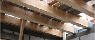
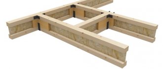
- Wooden
— they are used mainly in the construction of individual buildings. They are used in the construction of floors, ceilings, and load-bearing floors. Wood is a capricious material and is subject to deformation. To determine the maximum bending, the following parameters are essential: the profile used, size, load, nature of the cross section.
- Metal
— such beams are made from an alloy of metals and their cross-section is complex. Therefore, special attention is paid to the rigidity as well as the strength of the connections. Metal beams are used in the construction of high-rise buildings and structures that require high strength.
1. Collection of loads Before starting the calculation of a steel beam, it is necessary to collect the load acting on the metal beam. Depending on the duration of action, loads are divided into permanent and temporary.
Constant loads include:
- own weight of the metal beam;
- own weight of the floor, etc.;
Temporary loads include:
- long-term load (payload, taken depending on the purpose of the building);
- short-term load (snow load, taken depending on the geographical location of the building);
- special load (seismic, explosive, etc. Not taken into account within this calculator);
Loads on a beam are divided into two types: design and standard. Design loads are used to calculate the beam for strength and stability (1st limit state). Standard loads are established by standards and are used to calculate beams for deflection (2nd limit state). Design loads are determined by multiplying the standard load by the reliability load factor. Within the framework of this calculator, the design load is used to determine the deflection of the beam to reserve.
The general calculation of metal structures can be read on our website.
Loads can be collected on our website.
After you have collected the surface load on the floor, measured in kg/m2, you need to calculate how much of this surface load the beam takes on. To do this, you need to multiply the surface load by the pitch of the beams (the so-called load strip).
For example: We calculated that the total load was Qsurface = 500 kg/m2, and the beam spacing was 2.5 m.
Then the distributed load on the metal beam will be: Qdistributed = 500 kg/m2 * 2.5 m = 1250 kg/m. This load is entered into calculator 2. Constructing diagrams
Next, a diagram of moments and shear forces is constructed.
The diagram depends on the loading pattern of the beam and the type of beam support. The diagram is constructed according to the rules of structural mechanics. For the most frequently used loading and support schemes, there are ready-made tables with derived formulas for diagrams and deflections. 3. Calculation by strength and deflection
After constructing the diagrams, calculations are made by strength (1st limit state) and deflection (2nd limit state).
In order to select a beam based on strength, it is necessary to find the required moment of inertia Wtr and select a suitable metal profile from the assortment table. The vertical maximum deflection fult is taken according to table 19 from SNiP 2.01.07-85* (Loads and impacts). Point 2.a depending on the span. For example, the maximum deflection is fult=L/200 with a span of L=6m. means that the calculator will select a section of a rolled profile (I-beam, channel or two channels in a box), the maximum deflection of which will not exceed fult=6m/200=0.03m=30mm. To select a metal profile based on deflection, find the required moment of inertia Itr, which is obtained from the formula for finding the maximum deflection. And also a suitable metal profile is selected from the assortment table. 4. Selection of a metal beam from the assortment table
From the two selection results (1st and 2nd limit state), a metal profile with a large section number is selected.
Beam strength and rigidity
When designing, you should take into account the bending of the beams so that the structure is reliable, high-quality, durable and practical.
These parameters are influenced by the following factors:
- the magnitude of external loads, their position;
- parameters, character, finding the cross section;
- longitudinal quantities;
- material;
- number of supports, method of their fastening.
There are 2 methods of calculation: simple - a magnifying factor is used, and accurate - additionally includes border calculations.
Theory using the initial parameters method
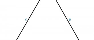
Let's take a cantilever beam loaded with concentrated force, moment, and distributed load. Thus, we will set up a calculation scheme where all types of loads are present, thereby covering the entire theoretical part to the maximum. Let us denote the support reactions in a rigid embedment that arise under the action of an external load:
Selecting a base and designating a coordinate system
For the beam, we will select a base on the left side, from which we will count the distances to the application of forces, moments, the beginning and end of the distributed load. We denote the base by the letter O and draw a coordinate system through it:
The base is traditionally chosen from the left edge of the beam, but you can also choose it from the right. Then the equation will have opposite signs, this may be useful in some cases and will simplify the solution a little. Understanding when to accept the base on the left or on the right will come with experience in solving problems using the initial parameters method.
Universal deflection equation for a beam
After introducing the base, coordinate system and designating the distances a, b, c, d, we write down a universal formula with the help of which we will calculate the deflection of the beam (vertical displacement of the section K located at the free end of the beam): Now let's talk about this formula, analyze it so to speak :
- E – elastic modulus;
- I – moment of inertia;
- Vk – deflection of section K;
- VO – deflection of section O;
- θO – angle of rotation of section O.
I will not give the derivation of this formula, I don’t want to scare off readers; advanced students can familiarize themselves with the derivation on their own in a textbook on strength of materials. I will only talk about the basic principles of this equation and how to write it for any beam of constant cross-section.
So, we study this formula from left to right. On the left side of the equation the desired deflection is indicated, in our case Vk, which is additionally multiplied by the stiffness of the beam - EI: The equation always takes into account the deflection of the beam section that coincides with our base EIVO:
Also, the angle of rotation of the section coinciding with the selected base is always taken into account. Moreover, the product EIθO is always multiplied by the distance from the base to the section whose deflection is being calculated; in our example, this is the distance r.
The following components of this equation take into account the entire load located to the left of the section under consideration. In parentheses, the distances from the base to the section are subtracted from the base to the corresponding force or moment, the beginning or end of the distributed load.
The bracket, in the case of concentrated forces, is raised to the 3rd power and divided by 6. If the force points upward, then we consider it positive, if downward, then it is written with a minus in the equation:
In the case of moments, the bracket is raised to the 2nd power and divided by 2. The sign of the moment will be positive when it is directed clockwise and negative, respectively, when it is directed counterclockwise.
Accounting for distributed load
Now let's talk about distributed load. As already mentioned, the equation of the initial parameters method must take into account the beginning and end of the distributed load, but its end coincides with the section whose deflection we want to calculate, so only its beginning enters the equation.
Moreover, it is important that even if there were a force or moment in this section, they would also not be taken into account. We are interested in everything that is to the left of the section under consideration.
For a distributed load, the bracket is raised to the 4th power and divided by 24. The sign rule is the same as for concentrated forces:
Border conditions
To solve the equation we need some more data. At first glance, we have three unknowns in the equation: VK, VO and θO. But we can glean something from the diagram itself. We know that in a rigid embedment there can be no deflections and no rotations, that is, VO=0 and θO=0, these are the so-called initial parameters or they are also called boundary conditions. Now, if we had a real problem, we would substitute all the numerical data and find the displacement of the section K.
If the beam were fixed using a pivotally movable and fixed support, then we would take the deflections in the supports equal to zero, but the angle of rotation in the supports would already be different from zero. This is described in more detail in my other article, devoted to the method of initial parameters using the example of a beam on two supports.
I almost forgot about one more quantity that often needs to be determined by the initial parameters method. As you know, when bending, the cross sections of beams, in addition to moving vertically (bending), also rotate through a certain angle. The rotation angles and deflections of the cross sections are related by a differential relationship.
Stiffness calculation
Calculation algorithm:
The formula indicates:
- M – max moment occurring in the beam;
- Wn,min – moment of resistance of the section (tabular indicator);
- Ry – bending resistance (calculated indicator);
- γc – indicator of working conditions (tabular indicator).
Such a calculation is not labor-intensive, but for a more accurate value the following is required:
- working plan of the facility;
- determination of the characteristics of the beam, the nature of the section;
- determination of the maximum load acting on the beam;
- estimation of the maximum deflection point;
- checking the strength of max bending moment.
Choosing a channel from the point of view of economic feasibility
The cost of a channel is calculated based on data on weight and cost per ton:
| Characteristics / Name | Channel 12P | Channel 140x60x5 |
| Weight of 1 meter, kg | 10,7 | 9,77 |
| Weight of a channel 6 meters long, kg | 64,2 | 58,6 |
| Price per ton* | RUB 94,190 | RUB 125,690 |
| Price for 1 piece of channel | 6047 rub. | 7365 rub. |
* Price as of June 2021, see the current prices on the date of purchase in the online store in the Rolled Metal section - Channel.
It can be noted that from the conditions for calculating the strength of a channel working in bending, a more economical solution would be to use a hot-rolled channel in comparison with a bent one.
Calculation of deflection and its features
It is necessary for all floors with high operational loads.
When applying the appropriate coefficients, adhere to the following:
- a beam supported by one rigid and one hinged support, subject to a concentrated load;
- a beam supported on a rigid and hinged support, subject to a distributed load;
- cantilever type load;
- impact of complex load.
How to achieve structural strength
According to the standards, the beam used on the overpass must have a bend of no more than one cm with a length of one and a half meters. At the same time, in other designs this indicator changes. In an individual house, attic beams can bend by one cm over a length of 2 m, and in multi-storey buildings the same centimeter should fall over a length of 2.5 m.
In order for the building to be reliable and durable, calculations must be carried out during the planning process of the building. It is at this moment that such an indicator as the bending of the beam is determined. After all, the less the beam bends, the higher the strength of the house. This way the ceiling gets an even weight distribution and keeps the house stable. If the beams bend too much, then the entire ceiling will be unreliable and over time the connections will break and the building will collapse.
Calculations are carried out using one of the following methods:
- Use an online calculator. This instrument is programmed with standard data.
- Use the reference book and, after comparing all the parameters, make the calculations yourself.
- Use the formula and independently calculate the bending of the beams.
In a room that has been in use for more than one year, it is possible to determine how bad its condition is only after the level of subsidence of the beams has been determined.