In order to connect parts together using rivets, pins, bolts, studs and screws, holes are usually required. For through holes for fasteners , there is a standard that recommends using nominal size values.
GOST 11284 − 75
| Through holes for fasteners | |||
| d | d1 | ||
| 1st row | 2nd row | 3rd row | |
| 1,0 | 1,1 | 1,2 | 1,3 |
| 1,2 | 1,3 | 1,4 | 1,5 |
| 1,4 | 1,5 | 1,6 | 1,8 |
| 1,6 | 1,7 | 1,8 | 2,0 |
| 1,8 | 2,0 | 2,1 | 2,2 |
| 2,0 | 2,2 | 2,4 | 2,6 |
| 2,5 | 2,7 | 2,9 | 3,1 |
| 3,0 | 3,2 | 3,4 | 3,6 |
| 3,5 | 3,7 | 3,9 | 4,2 |
| 4,0 | 4,3 | 4,5 | 4,8 |
| 4,5 | 4,8 | 5,0 | 5,3 |
| 5,0 | 5,3 | 5,5 | 5,8 |
| 6,0 | 6,4 | 6,6 | 7,0 |
| 7,0 | 7,4 | 7,6 | 8,0 |
| 8,0 | 8,4 | 9,0 | 10,0 |
| 10,0 | 10,5 | 11,0 | 12,0 |
| 12,0 | 13,0 | 14,0 (13,5) | 15,0 (14,5) |
| 14,0 | 15,0 | 16,0 (15,5) | 17,0 (16,5) |
| 16,0 | 17,0 | 18,0 (17,5) | 19,0 (18,5) |
| 18,0 | 19,0 | 20,0 | 21,0 |
| 20,0 | 21,0 | 22,0 | 24,0 |
| 22,0 | 23,0 | 24,0 | 26,0 |
| 24,0 | 25,0 | 26,0 | 28,0 |
| 27,0 | 28,0 | 30,0 | 32,0 |
| 30,0 | 31,0 | 33,0 | 35,0 |
| 33,0 | 34,0 | 36,0 | 38,0 |
| 36,0 | 37,0 | 39,0 | 42,0 |
| 39,0 | 40,0 | 42,0 | 45,0 |
| 42,0 | 43,0 | 45,0 | 48,0 |
| 45,0 | 46,0 | 48,0 | 52,0 |
| 48,0 | 50,0 | 52,0 | 56,0 |
| 52,0 | 54,0 | 56,0 | 62,0 |
| 56 | 58 | 62 | 66 |
| 60 | 62 | 66 | 70 |
| 64 | 66 | 70 | 74 |
| 68 | 70 | 74 | 78 |
| 72 | 74 | 78 | 82 |
| 76 | 78 | 82 | 86 |
| 80 | 82 | 86 | 91 |
| 85 | 87 | 91 | 96 |
| 90 | 93 | 96 | 101 |
| 95 | 98 | 101 | 107 |
| 100 | 104 | 107 | 112 |
| 105 | 109 | 112 | 117 |
| 110 | 114 | 117 | 122 |
| 115 | 119 | 122 | 127 |
| 120 | 124 | 127 | 132 |
| 125 | 129 | 132 | 137 |
| 130 | 134 | 137 | 144 |
| 140 | 144 | 147 | 155 |
| 150 | 155 | 158 | 165 |
| 160 | 165 | 168 | 175 |
Part connections
All connections of various parts that are used in mechanical engineering and instrument making are divided into movable and fixed. In this case, those that ensure the movement of parts relative to each other are considered movable, and those that require rigid fastening between them are considered stationary.
The possibility of repeated assembly and disassembly of components and assemblies of machines and equipment is ensured by detachable connections. These include threaded, splined, keyed, profile, pin and terminal.
Unlike detachable ones, permanent connections cannot be disassembled without damaging the parts. These include welded, adhesive, soldered, riveted joints, as well as joints with guaranteed interference. In technology, connections play an extremely important role, and many malfunctions in the operation of machines and equipment, as well as accidents, often occur because their parts were poorly connected to each other.
GOST 11284—75 Through holes for fasteners.
- TPA Directory
- GOST and standards for pipeline fittings
- GOST 11284—75 Through holes for fasteners. GOST 11284—75 Through holes for fasteners.
GOST 11284—75 Through holes for fasteners. GOST 11284—75 Through holes for fasteners. 1. This standard establishes the dimensions of through holes for bolts, screws, studs and rivets with rod diameters from 1.0 to 160 mm, used to connect parts with gaps. The standard fully complies with the CMEA standardization recommendation PC 107-72 and the ISO recommendation P-273. 2. The dimensions of through holes must correspond to those indicated in the table. Table 1
| Diameters of fastener rods d | Diameters of through holes d1 | Diameters of fastener rods d | Diameters of through holes d1 | ||||
| 1st row | 2nd row | 3rd row | 1st row | 2nd row | 3rd row | ||
| 1,0 | 1,2 | 1,3 | — | 2,5 | 2,7 | 2,9 | 3,1 |
| 1,2 | 1,4 | 1,5 | — | 3,0 | 3,2 | 3,4 | 3,6 |
| 1,4 | 1,6 | 1,7 | — | 4,0 | 4,3 | 4,5 | 4,8 |
| 1,6 | 1,7 | 1,8 | 2,0 | 5,0 | 5,3 | 5,5 | 5,8 |
| 2.0 | 2,2 | 2,4 | 2,6 | 6,0 | 6,4 | 6,6 | 7,0 |
table 2
| Diameters of fastener rods d | Diameters of through holes d1 | Diameters of fastener rods d | Diameters of through holes d1 | ||||
| 1st row | 2nd row | 3rd row | 1st row | 2nd row | 3rd row | ||
| 7,0 | 7,4 | 7,6 | 8,0 | 56 | 58 | 62 | 66 |
| 8,0 | 8,4 | 9,0 | 10,0 | 60 | 62 | 66 | 70 |
| 10,0 | 10,5 | 11,0 | 12,0 | 64 | 66 | 70 | 74 |
| 12,0 | 13,0 | 14,0 | 15,0 | 68 | 70 | 74 | 78 |
| 14,0 | 15,0 | 16,0 | 17,0 | 72 | 74 | 78 | 82 |
| 16,0 | 17,0 | 18,0 | 19,0 | 76 | 78 | 82 | 86 |
| 18,0 | 19,0 | 20,0 | 21,0 | 80 | 82 | 86 | 91 |
| 20,0 | 21,0 | 22,0 | 24,0 | 85 | 87 | 91 | 96 |
| 22,0 | 23,0 | 24,0 | 26,0 | 90 | 93 | 96 | 101 |
| 24,0 | 25,0 | 26,0 | 28,0 | 95 | 98 | 101 | 107 |
| 27,0 | 28,0 | 30,0 | 32,0 | 100 | 104 | 107 | 112 |
| 30,0 | 31,0 | 33,0 | 35,0 | 105 | 109 | 112 | 117 |
| 33,0 | 34,0 | 36,0 | 38,0 | 110 | 114 | 117 | 122 |
| 36.0 | 37,0 | 39,0 | 42,0 | 115 | 119 | 122 | 127 |
| 39,0 | 40,0 | 42,0 | 45,0 | 120 | 124 | 127 | 132 |
| 42,0 | 43,0 | 45,0 | 48,0 | 125 | 129 | 132 | 137 |
| 45,0 | 46,0 | 48,0 | 52,0 | 130 | 134 | 137 | 144 |
| 48,0 | 50,0 | 52,0 | 56,0 | 140 | 144 | 147 | 155 |
| 52,0 | 54,0 | 56,0 | 62,0 | 150 | 155 | 158 | 165 |
| 160 | 165 | 168 | 175 | ||||
Pipe fittings portal Armtorg.ru
Barnaul, Zavodskoy 9th passage, 5g/8.
+7 (3852) 567-734; +7 (3852) 226-927
Share
Previous article Next article
← return to the section GOST and standards for pipeline fittings ← return to the table of contents of the directory
Latest registered companies(Register a company)
Online Capital Financing
Russia, Arkhangelsk region
WestMedGroup LLC
Russia, Moscow region
LLC "NefteSpetsServis"
Russia, Republic of Bashkortostan Product cloud
.Other...2043 Safety valve blocks127 Bronze valves122 Steel valves952 Cast iron valves571 Energy valves144 Stainless steel valves370 Steel valves2163 Steel valves - HL371 Cast iron valves1101 Energy valves86 Steel valves293 Cast iron valves33 6 Test equipment for injection molding machines119 Check valves974 Shut-off valves61 Safety valves1120 Control valves559 Energy valves128 Bellows compensators203 Steel condensate drains55 Cast iron condensate drains67 Boiler equipment220 Bronze taps149 Stainless steel taps178 Steel taps608 Steel taps - HL87 Cast iron taps149 Pressure gauges88 Hardware433 Pumps247 Bends1081 Heating equipment96 Switching devices46 Transitions461 Fire fittings48 Radiators33 Control fittings34 1 Repair equipment for injection molding machines53 Water meters154 Thermometers38 Tees493 Pipes702 Level indicators71 Sealing materials67 Filters, strainers410 Fittings206 Flanges2400 Ball valves1244 Electric drives249
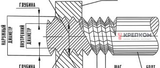
Hole Machining Methods
The holes differ from each other not only in diameter, but also in the processing method, and are divided into several types.
1) Mounting holes. They are most often made on drilling machines and in terms of processing accuracy they correspond to the eleventh and twelfth qualifications.
2) Smooth and stepped holes of parts having the shape of bodies of revolution. In most cases, they are made on lathes by drilling, reaming, countersinking or boring.
3) Critical openings of body parts. They are manufactured using both universal and specialized equipment and correspond to the seventh qualification and higher.
4) Deep holes having more than five times the length to diameter ratio. They are manufactured on specialized equipment.
5) Shaped and conical holes. They are manufactured using tools with curved or conical cutting edges, as well as copying and boring methods.
6) Profile holes (having a cross-section other than round). They are made by chiseling, stitching or drawing.
Drill and hole size chart for metric and inch threads
Let's consider the calculation results from GOST 19257-73:
- For M3 threads, a tap is required, for which the standard pitch is 0.5, drills are 2.5 mm.
- For M4 threads, a tap is required, for which the standard pitch is 0.7, drill bits are 3.3 mm.
- For M5 threads, a tap is required, for which the standard pitch is 0.8, drill bits are 4.2 mm.
- For M6 threads, a tap is required, for which the standard pitch is 1.0, drill bits are 5.0 mm.
- For M8 threads, a tap is required, for which the standard pitch is 1.25, drill bits are 6.75 mm.
- For M10 threads, a tap is required, for which the standard pitch is 1.5, drills are 8.5 mm.
- For M12 threads, a tap is required, for which the standard pitch is 1.75, drill bits are 10.25 mm.
- For M16 threads, a tap is required, for which the standard pitch is 2.0, drills are 13.5 mm.
Despite the fact that the metric system is the most popular, we recommend that you familiarize yourself with the table of threaded drill diameters:
Spaces for screw heads
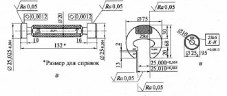
SURFACE ROUGHNESS
(according to GOST 2789-73)
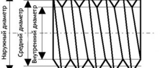
Surface roughness, according to GOST 2789-73 and ISO P468, is a set of surface irregularities with relatively small steps along the base length l
.
The base length l is the length of the base line used to highlight irregularities that characterize the surface roughness and to quantify its parameters. The numerical values of surface roughness are determined from a single base, which is taken to be the middle line of the profile m . The roughness reference system from the profile centerline m
M
system .
The surface roughness is determined quantitatively regardless of the method of its processing. M system
Surface roughness can be assessed by one or more parameters, but the most widely used in mechanical engineering are the arithmetic mean deviation of the profile Ra and the height of profile irregularities at ten points Rz within the base length. The unit of measurement for these parameters is µm (micrometer).
The Ra parameter is preferred.
For numerical values of roughness parameters, see clause 1.1 and clause 1.2.
Arithmetic mean profile deviation Ra, µm
| 100 80 63 50 40 32 25 20 16,0 12,5 | 10,0 8,0 6,3 5,0 4,0 3,2 2,5 2,0 1,6 1,25 | 1,0 0,8 0,63 0,5 0,4 0,32 0,25 0,2 0,16 0,125 | 0,1 0,08 0,063 0,05 0,04 0,032 0,025 0,02 0,016 0,012 | 0,01 0,08 — — — — — — — — |
Height of profile irregularities at 10 points Rz, µm
| — — — — — — — — 1600 1250 | 1000 800 630 500 400 320 250 200 160 125 | 100 80 63 50 40 32 25 20 16,0 12,5 | 10,0 8,0 6,3 5,0 4,0 3,2 2,5 2,0 1,6 1,25 | 1,0 0,80 0,63 0,5 0,4 0,32 0,25 0,2 0,16 0,125 | 0,1 0,08 0,063 0,05 0,04 0,032 0,025 — — — |
Correspondence between the values of roughness parameters
(GOST 2789-73)
| Roughness parameters, microns | Base length l, mm | |
| Ra | Rz | |
| 80 40 20 | 320 160 80 | 8,0 |
| 10 5 | 40 20 | 2,5 |
| 2,5 1,25 | 10 6,3 | 0,8 |
| 0,63 0,32 0,16 0,08 0,04 | 3,2 1,6 0,8 0,4 0,2 | 0,25 |
| 0,02 0,01 | 0,1 0,05 | 0,08 |
Surface roughness depending on types of processing
Surface roughness of castings
| Type of casting | Metals | Casting surface roughness parameters, microns |
| In sandy forms | Ferrous metals Non-ferrous metals | Ra 80…Ra 40 Ra 80…Ra 20 |
| In the chill mold | Ferrous metals Non-ferrous metals | Ra 80…Ra 10 Ra 40…Ra 5 |
| By investment models | Ferrous metals Non-ferrous metals | Ra 20…Ra 5 Ra 20…Ra 2.5 |
| Shell casting | Ferrous metals Non-ferrous metals | Ra 40…Ra 10 Ra 20…Ra 5 |
| Under pressure | Aluminum alloys Copper alloys | Ra 10…Ra 2.5 |
Surface roughness during machining
| Processed surfaces | Processing methods | Roughness parameters Ra, µm | |||||||||||||||||||
| 80 | 40 | 20 | 10 | 5 | 2,5 | 1,25 | 0,63 | 0,32 | 0,16 | 0,08 | |||||||||||
| External cylindrical | Grinding | Draft | + | + | + | + | |||||||||||||||
| Finishing | + | + | + | + | + | ||||||||||||||||
| Thin | + | + | + | ||||||||||||||||||
| Grinding | Draft | + | + | ||||||||||||||||||
| Finishing | + | + | |||||||||||||||||||
| Thin | + | + | |||||||||||||||||||
| Finishing with abrasive cloth | + | + | + | + | |||||||||||||||||
| Internal cylindrical | Boring | Draft | + | + | + | + | |||||||||||||||
| Finishing | + | + | + | + | |||||||||||||||||
| Thin | + | + | + | ||||||||||||||||||
| Drilling | + | + | + | ||||||||||||||||||
| Countersinking | Draft | + | + | + | |||||||||||||||||
| Finishing | + | + | + | + | |||||||||||||||||
| Deployment | Normal | + | + | ||||||||||||||||||
| Accurate | + | + | |||||||||||||||||||
| Thin | + | + | |||||||||||||||||||
| Internal grinding | Draft | + | + | ||||||||||||||||||
| Finishing | + | + | + | ||||||||||||||||||
| Planes | Planing | Draft | + | + | + | + | |||||||||||||||
| Finishing | + | + | + | + | + | ||||||||||||||||
| Thin | + | + | |||||||||||||||||||
| Cylinder milling | Draft | + | + | + | + | ||||||||||||||||
| Finishing | + | + | + | ||||||||||||||||||
| Thin | + | + | + | ||||||||||||||||||
| Face milling | Draft | + | + | + | + | ||||||||||||||||
| Finishing | + | + | + | ||||||||||||||||||
| Thin | + | + | |||||||||||||||||||
| Surface grinding | Draft | + | + | ||||||||||||||||||
| Finishing | + | ||||||||||||||||||||
Typical surfaces of parts and their roughness parameters
| Roughness parameters Ra, µm | Typical surfaces and details |
| 80…40 | Non-working surfaces of parts |
| 20 | Holes for the passage of fasteners Recesses, grooves Holes for oil channels Soles and bases of housings, frames, paws |
| 10 | Free non-mating end surfaces of shafts, bushings Surfaces of flanges and covers of leaking joints |
| 5 | Working surfaces of metric, inch, conical external and internal threads (when cutting with a tap and die) Working surfaces of trapezoidal, persistent, rectangular internal threads Surfaces of bushings, rings, hubs adjacent to other surfaces, but not landing |
| 2,5 | Grooves for sealing rubber rings for moving and fixed joints Thrust shoulders for rolling bearings Working surfaces of metric, inch, conical external and internal threads (when cutting with a cutter) Working surfaces of trapezoidal, thrust, rectangular external threads |
| 1,25 | Cylinders working with rubber cuffs Holes of plain bearings Friction surfaces of lightly loaded parts Cutting surfaces of lead screws and nuts Seating surfaces on shafts and in housings for rolling bearings with a diameter of up to 80...100 m Sliding guides of normal accuracy Runs of V-belt pulleys Rods and journals of shafts in seals with stuffing box felt rings |
| 0,63 | Shaft rods and journals are sealed with rubber cuffs Sliding guides of increased precision Rolling surfaces of rollers, wheels, rollers |
| 0,32 | Handles, flywheel rims, steering wheels, handles |
STRUCTURAL ELEMENTS
2.1. Through holes for fasteners
(bolts, screws, studs)
(see picture to clause 2.2)
| Diameter of fastener rod d , mm | Hole diameter d1 , mm | Diameter of fastener rod d , mm | Hole diameter d1 , mm |
| 4,0 | 4,5 | 16,0 | 18,0 |
| 5,0 | 5,5 | 18,0 | 20,0 |
| 6,0 | 6,6 | 20,0 | 22,0 |
| 8,0 | 9,0 | 22,0 | 24,0 |
| 10,0 | 11,0 | 24,0 | 26,0 |
| 12,0 | 14,0 | 27,0 | 30,0 |
| 14,0 | 16,0 | 30,0 | 33,0 |
2.2. Nominal values of hole diameters for metric threads (coarse pitch) of normal accuracy
| Thread diameter d | Thread pitch P | Thread hole diameter d1 |
| 5 | 0,8 | 4,23 |
| 6 | 1,0 | 5,0 |
| 8 | 1,25 | 6,75 |
| 10 | 1,5 | 8,5 |
| 12 | 1,75 | 10,25 |
| 14 | 2,0 | 11,95 |
| 16 | 13,95 | |
| 18 | 2,5 | 15,4 |
| 20 | 17,4 | |
| 22 | 19,4 | |
| 24 | 3,0 | 20,9 |
| 27 | 23,9 | |
| 30 | 3,5 | 26,35 |
| 33 | 29,35 | |
| 36 | 4,0 | 31,85 |
Spaces for screw heads
| Thread diameter d , mm | Pan head screws | Countersunk and semi-countersunk head screws D | |||||
| D | H1 | H2 | H3 | H4 | d1 | ||
| 4 | 8 | 4 | 5.5 | 2,8 | 4 | 4,5 | 8,3 |
| 5 | 10 | 5 | 7 | 3,5 | 5 | 5,5 | 10,3 |
| 6 | 12 | 6 | 8 | 4 | 6 | 6,6 | 12,3 |
| 8 | 15 | 8 | 11 | 5 | 7,5 | 9,0 | 16,5 |
| 10 | 18 | 10 | 13 | 6 | 9 | 11,0 | 20 |
| 12 | 20 | 12 | 16 | 7 | 11 | 14,0 | 24 |
| 14 | 24 | 14 | 18 | 8 | 12 | 16,0 | 28 |
| 16 | 28 | 16 | 20 | 9 | 13 | 18,0 | 31 |
| 18 | 30 | 18 | 23 | 10 | 15 | 20,0 | 35 |
| 20 | 34 | 20 | 25 | 11 | 16 | 22,0 | 39 |
Notes
: 1. Dimensions
H2
and
H4
are given for normal and light spring washers according to
GOST 6402-70.
2. Dimensions H1
…
H4
should be used if the cutting depth under the head is not
indicated on the general view drawing.
2.4. Places for hex nuts and bolt heads
With and without washers
| Thread diameter d | Key size S | D | D1 |
| 5 | 8 | 12 | 12 |
| 6 | 10 | 14 | 14 |
| 8 | 12 | 18 | — |
| 14 | 20 | 20 | |
| 10 | 14 | 20 | — |
| 17 | 24 | 26 | |
| 12 | 17 | 24 | — |
| 19 | 26 | 28 | |
| 16 | 22 | 30 | — |
| 24 | 32 | 34 | |
| 20 | 27 | 36 | — |
| 30 | 40 | 40 | |
| 24 | 32 | 42 | — |
| 36 | 45 | 50 |
Notes
: 1. Dimensions
D
for hex nuts and bolt heads without washers or with
spring washers GOST 6402-70.
2. Dimensions D1
for hex nuts and flat head bolts
washers GOST 11371-78.
3. Trimming depth h
specified by a general drawing.
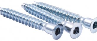
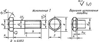
Main types of bolts
In accordance with GOST 27017-86 “Fastening products. Terms and definitions "bolt" is a fastener in the form of a rod with an external thread at one end, with a head at the other, forming a connection using a nut or threaded hole in one of the connected products. Note that a screw receives a similar definition in the standard: a fastener for forming a connection or fixation, made in the form of a rod with an external thread at one end and a structural element for transmitting torque at the other.
There is still no complete clarity on the question of how a bolt differs from a screw. For example, a bolt is sometimes considered to have an incomplete thread, although there are bolts with full threads. If the thread is not made along the entire length of the bolt, then the diameter of the smooth part of the rod is approximately the same as the diameter of the thread measured at the tops of its turns. But there are also exceptions.
Sometimes they say that a bolt must have a hex head. But, at the same time, bolts are products with a semicircular and countersunk head. Let's look at the most popular bolt options available in the TsKI assortment.
The hex head is produced in several modifications: basic, with a support ledge, with a collar, with a flange.
Bolts with hexagonal head and main thread are divided into bolts with full (DIN 933) and partial thread (DIN 931) and fine and ultra-fine thread pitch (DIN 960 and DIN 961).
Separately, hex head bolts with an increased spanner size are available for highly loaded prestressed threaded connections in steel structures DIN 6914.
Bolts with a reduced wrench size are available in a variety of designs.
Along with hex heads, bolts can have a semicircular head:
low with square head (DIN 603) with mustache (DIN 607)
And the secret head:
with mustache (DIN 604) with high and low square head (DIN 608)
The definition of “furniture” is consistently applied to such bolts. This is partly due to the fact that some of them are widely used in furniture production. At the same time, the mustache and headrests prevent the product from turning during assembly.
Examples of bolts called by purpose are “hinged” and “welded”.
Instead of the usual head, the DIN 444 hinged bolt has a bushing with a through hole - it is also called a ring. Typically, the bushing sits on an axle and the bolt rotates around it. The thickness of the ring and the length of the thread in the design may vary.
A welded bolt looks little like a bolt at all. In place of his head there is a small cylindrical protrusion. Often this product is also called a welded pin.
It is he who ensures butt welding of the bolt and the base. Instead of a threaded cylinder, other external elements can be welded.
The formal name “bolt” also includes anchor and fitting bolts.
Anchor bolts are designed to be embedded in concrete. Their rod has a thread at one end - the one that goes out. The shape of the other end may vary.
Its task is to provide maximum resistance to the anchor being pulled out from the base. Therefore, the second end is given an expanding shape. When installing the bolt, this part is lowered into the hole and filled with concrete.
A fit bolt is a bolt whose diameter of the smooth part of the rod allows it to be installed without a gap in a precisely machined hole. For this purpose, the threaded part is made of a deliberately smaller diameter.
A “fit” bolt DIN 609 is a distortion of “precision”, that is, high accuracy. Also used as fitting bolts are “Bolts with a hexagonal reduced head of accuracy class A for holes from under the reamer. GOST 7817-80".
Installation conditions and diameters of preliminary holes for self-tapping screws BEST-Fixtures
Experienced craftsmen also remember those times when several self-tapping screws were used at once to create just one fastening using a self-tapping screw! The installation method was simple, but required a mandatory technological sequence. The first screw was screwed in 2/3 of its length and, to avoid licking the slot on the head, was unscrewed and thrown out. The second was to cut a thread in the base to the full depth of the fastening and again, unscrew it and throw it away. The concerns were quite serious - the licked slot on the head of the screw prevents its unhindered unscrewing if necessary (Fig. 7). Those. The first two self-tapping screws served as a kind of tap - a tool for cutting threads. And only the last, third, screw served its intended purpose: to form a threaded fastener. In everyday life, they often avoided the advice of “experienced” people and, applying considerable pressure on a screwdriver, screwed a self-tapping screw into the base. In this case, the slot on the head was indeed damaged, but with sufficient effort this did not interfere with installing the self-tapping screw in the designed position. As a result: after 2-3 years of use, even indoors, the hardware sometimes became covered with rust and when replacing it, it was almost impossible to unscrew them without the help of pliers and a drill.
Currently, against the backdrop of the widespread use of threaded fasteners, they have a serious responsibility. The requirements for fasteners have also become significantly stricter. New technologies for the production of steel and their processing make it possible to produce hardware for use in completely different operating conditions. For example, fasteners made of A2 and A4 steel in accordance with GOST R ISO 3506 can be used even when exposed to aggressive environments without the formation of corrosion or at extremely high and low temperatures without fear of destruction of the fastener. For various installation methods and materials with different properties, special spline shapes have been developed: Philips, Pozidrive, Torx, etc.
All this is implemented in a line of self-tapping screws, the so-called self-tapping screws, BEST-Fasteners. Which are made of high-alloy chromium-nickel stainless steel. The correct choice of head slot from a wide range of models ensures smooth installation of our self-tapping screws into all kinds of bases using a power tool or manually. The high strength of these hardware allows the product to cut a landing thread when screwing them into a pre-drilled hole in the base. Depending on the base: wood, plastics, composite materials, metals, etc., the design of the thread of BEST-Fixture screws also differs significantly. Self-tapping screws, the threads of which are made in accordance with GOST R ISO 1478-93 (or ISO 1478) are intended for installation, primarily in metals and other hard materials. As can be seen from the name of the regulatory documents, they are completely identical. According to them, the thread of self-tapping screws is designated ST and the numerical value of the nominal (external) diameter of the thread of the product, as well as its length, for example:
ST4.8 x25,
Where:
ST – thread type, the parameters of which fully comply with GOST R ISO 1478-93 (or ISO 1478),
4.8 – nominal (external) thread diameter in mm,
25 – thread length in mm.
Screwing screws into metals and other solid materials is carried out using powerful torques with a significant load on the head of the hardware or its slots. Acceptable fastenings of sheet materials using self-tapping screws are shown in Figures 1-6. Their installation requires compliance with strict technical regulations. Failure to comply with which can lead to undesirable results, for example: “licking” of the slots on the head (Fig. 7), bending of the thread (Fig. 8) or deformation of the entire self-tapping screw (Fig. 9).
When installing self-tapping screws BEST-Fasteners with threads in accordance with GOST R ISO 1478-93, we recommend following the German standard DIN 7975 Self-tapping screws. Pre-hole and installation guide.
DIN 7975 provides 6 types of fastening:
| Fig.7 “Licking” the slot on the head of a self-tapping screw. Occurred as a result of screwing a screw into plywood without a preliminary hole | |
| Fig.8 Collapse of the thread of a self-tapping screw. The cause of the defect was the screwing of an A2 steel screw into a carbon steel profile. Shelf thickness 4 mm. | |
| Fig.9 Deformation and breakage of the self-tapping screw. The cause of the defect was the screwing of an A2 steel screw into a carbon steel profile. Shelf thickness 4 mm. |
In this case, the permissible thickness of the fastened materials specified in Table 1 of DIN 7975 must be observed:
| Thread size | ST 2.2 | ST 2.9 | ST 3.5 | ST 3.9 | ST 4.2 | ST 4.8 | ST 5.5 | ST 6.3 | ST 8 |
| Minimum permissible sheet thickness*, mm | 0.35 | 0.58 | 0.69 | 0.63 | 0.65 | 0.75 | 0.81 | 0.86 | 0.91 |
| Minimum thickness of materials to be bonded, mm | 0.8 | 1.1 | 1.3 | 1.3 | 1.4 | 1.6 | 1.8 | 1.8 | 2.1 |
| Maximum thickness of materials to be bonded, mm | 1.8 | 2.2 | 2.8 | 3 | 3.5 | 4 | 4.5 | 5 | 6.5 |
* - which is capable of ensuring that the sheet engages the thread of a self-tapping screw with the types of fastening shown in Fig. 3-5
For the types of fastenings shown in Fig. 1 and 2, holes are pre-drilled. The diameters, depending on the thickness and strength of the materials being fastened, are indicated in Table 2 for each size of self-tapping screws.
Table 2.1 Diameters of preliminary holes (mm) for self-tapping screws ST 2.2
| Total thickness of fastened products, mm | Material strength, Rm, N/mm2 | ||||||||
| 100 | 150 | 200 | 250 | 300 | 350 | 400 | 450 | 500 | |
| 0,8 | 1,7 | 1,7 | 1,7 | 1,7 | 1,7 | 1,7 | 1,7 | 1,7 | 1,7 |
| 0,9 | 1,7 | 1,7 | 1,7 | 1,7 | 1,7 | 1,7 | 1,7 | 1,7 | 1,7 |
| 1,0 | 1,7 | 1,7 | 1,7 | 1,7 | 1,7 | 1,7 | 1,7 | 1,7 | 1,8 |
| 1,1 | 1,7 | 1,7 | 1,7 | 1,7 | 1,7 | 1,7 | 1,7 | 1,8 | 1,8 |
| 1,2 | 1,7 | 1,7 | 1,7 | 1,7 | 1,7 | 1,7 | 1,8 | 1,8 | 1,8 |
| 1,3 | 1,7 | 1,7 | 1,7 | 1,7 | 1,7 | 1,8 | 1,8 | 1,8 | 1,8 |
| 1,4 | 1,7 | 1,7 | 1,7 | 1,7 | 1,7 | 1,8 | 1,8 | 1,8 | 1,9 |
| 1,5 | 1,7 | 1,7 | 1,7 | 1,7 | 1,8 | 1,8 | 1,8 | 1,9 | 1,9 |
| 1,6 | 1,7 | 1,7 | 1,7 | 1,8 | 1,8 | 1,8 | 1,9 | 1,9 | 1,9 |
| 1,7 | 1,7 | 1,7 | 1,7 | 1,8 | 1,8 | 1,9 | 1,9 | 1,9 | 1,9 |
| 1,8 | 1,7 | 1,7 | 1,8 | 1,8 | 1,8 | 1,9 | 1,9 | 1,9 | 1,9 |
Table 2.2 Diameters of preliminary holes (mm) for self-tapping screws ST 2.9
| Total thickness of fastened products, | Material strength, Rm, N/mm2 | ||||||||
| 100 | 150 | 200 | 250 | 300 | 350 | 400 | 450 | 500 | |
| 1,1 | 2,2 | 2,2 | 2,2 | 2,2 | 2,2 | 2,2 | 2,2 | 2,2 | 2,3 |
| 1,2 | 2,2 | 2,2 | 2,2 | 2,2 | 2,2 | 2,2 | 2,2 | 2,2 | 2,3 |
| 1,3 | 2,2 | 2,2 | 2,2 | 2,2 | 2,2 | 2,2 | 2,2 | 2,3 | 2,3 |
| 1,4 | 2,2 | 2,2 | 2,2 | 2,2 | 2,2 | 2,2 | 2,3 | 2,3 | 2,4 |
| 1,5 | 2,2 | 2,2 | 2,2 | 2,2 | 2,2 | 2,3 | 2,3 | 2,4 | 2,4 |
| 1,6 | 2,2 | 2,2 | 2,2 | 2,2 | 2,3 | 2,3 | 2,4 | 2,4 | 2,4 |
| 1,7 | 2,2 | 2,2 | 2,2 | 2,2 | 2,3 | 2,4 | 2,4 | 2,4 | 2,4 |
| 1,8 | 2,2 | 2,2 | 2,2 | 2,3 | 2,3 | 2,4 | 2,4 | 2,4 | 2,5 |
| 1,9 | 2,2 | 2,2 | 2,2 | 2,3 | 2,4 | 2,4 | 2,4 | 2,5 | 2,5 |
| 2,0 | 2,2 | 2,2 | 2,3 | 2,3 | 2,4 | 2,4 | 2,5 | 2,5 | 2,5 |
| 2,2 | 2,2 | 2,2 | 2,3 | 2,4 | 2,4 | 2,5 | 2,5 | 2,5 | 2,5 |
Table 2.3 Diameters of preliminary holes (mm) for self-tapping screws ST 3.5
| Total thickness of fastened products, | Material strength, Rm, N/mm2 | ||||||||
| 100 | 150 | 200 | 250 | 300 | 350 | 400 | 450 | 500 | |
| 1,3 | 2,6 | 2,6 | 2,6 | 2,6 | 2,6 | 2,6 | 2,7 | 2,7 | 2,8 |
| 1,4 | 2,7 | 2,7 | 2,7 | 2,7 | 2,7 | 2,7 | 2,7 | 2,8 | 2,8 |
| 1,5 | 2,7 | 2,7 | 2,7 | 2,7 | 2,7 | 2,7 | 2,8 | 2,8 | 2,9 |
| 1,6 | 2,7 | 2,7 | 2,7 | 2,7 | 2,7 | 2,7 | 2,8 | 2,9 | 2,9 |
| 1,7 | 2,7 | 2,7 | 2,7 | 2,7 | 2,7 | 2,8 | 2,8 | 2,9 | 2,9 |
| 1,8 | 2,7 | 2,7 | 2,7 | 2,7 | 2,8 | 2,8 | 2,9 | 2,9 | 2,9 |
| 1,9 | 2,7 | 2,7 | 2,7 | 2,7 | 2,8 | 2,9 | 2,9 | 2,9 | 3,0 |
| 2,0 | 2,7 | 2,7 | 2,7 | 2,8 | 2,9 | 2,9 | 2,9 | 3,0 | 3,0 |
| 2,2 | 2,7 | 2,7 | 2,8 | 2,8 | 2,9 | 3,0 | 3,0 | 3,0 | 3,0 |
| 2,5 | 2,7 | 2,7 | 2,9 | 2,9 | 3,0 | 3,0 | 3,0 | 3,1 | 3,1 |
| 2,8 | 2,7 | 2,8 | 2,9 | 3,0 | 3,0 | 3,0 | 3,1 | 3,1 | 3,1 |
Table 2.4 Diameters of preliminary holes (mm) for self-tapping screws ST 3.9
| Total thickness of fastened products, | Material strength, Rm, N/mm2 | ||||||||
| 100 | 150 | 200 | 250 | 300 | 350 | 400 | 450 | 500 | |
| 1,3 | 2,9 | 2,9 | 2,9 | 2,9 | 2,9 | 2,9 | 3,0 | 3,0 | 3,1 |
| 1,4 | 2,9 | 2,9 | 2,9 | 2,9 | 2,9 | 3,0 | 3,1 | 3,1 | 3,1 |
| 1,5 | 3,0 | 3,0 | 3,0 | 3,0 | 3,0 | 3,0 | 3,1 | 3,1 | 3,2 |
| 1,6 | 3,0 | 3,0 | 3,0 | 3,0 | 3,0 | 3,1 | 3,1 | 3,2 | 3,2 |
| 1,7 | 3,0 | 3,0 | 3,0 | 3,0 | 3,1 | 3,1 | 3,2 | 3,2 | 3,3 |
| 1,8 | 3,0 | 3,0 | 3,0 | 3,0 | 3,1 | 3,2 | 3,2 | 3,3 | 3,3 |
| 1,9 | 3,0 | 3,0 | 3,0 | 3,1 | 3,2 | 3,2 | 3,3 | 3,3 | 3,3 |
| 2,0 | 3,0 | 3,0 | 3,0 | 3,1 | 3,2 | 3,2 | 3,3 | 3,3 | 3,3 |
| 2,2 | 3,0 | 3,0 | 3,1 | 3,2 | 3,2 | 3,3 | 3,3 | 3,3 | 3,4 |
| 2,5 | 3,0 | 3,0 | 3,2 | 3,3 | 3,3 | 3,3 | 3,4 | 3,4 | 3,4 |
| 2,8 | 3,0 | 3,2 | 3,3 | 3,3 | 3,4 | 3,4 | 3,4 | 3,4 | 3,4 |
| 3,0 | 3,0 | 3,2 | 3,3 | 3,3 | 3,4 | 3,4 | 3,4 | 3,4 | 3,5 |
Table 2.5 Diameters of preliminary holes (mm) for self-tapping screws ST 4.2
| Total thickness of fastened products, | Material strength, Rm, N/mm2 | ||||||||
| 100 | 150 | 200 | 250 | 300 | 350 | 400 | 450 | 500 | |
| 1,4 | 3,1 | 3,1 | 3,1 | 3,1 | 3,1 | 3,1 | 3,2 | 3,3 | 3,4 |
| 1,5 | 3,2 | 3,2 | 3,2 | 3,2 | 3,2 | 3,2 | 3,2 | 3,3 | 3,4 |
| 1,6 | 3,2 | 3,2 | 3,2 | 3,2 | 3,2 | 3,2 | 3,3 | 3,4 | 3,4 |
| 1,7 | 3,2 | 3,2 | 3,2 | 3,2 | 3,2 | 3,3 | 3,3 | 3,4 | 3,4 |
| 1,8 | 3,2 | 3,2 | 3,2 | 3,2 | 3,3 | 3,3 | 3,4 | 3,4 | 3,5 |
| 1,9 | 3,2 | 3,2 | 3,2 | 3,2 | 3,3 | 3,4 | 3,4 | 3,4 | 3,5 |
| 2,0 | 3,2 | 3,2 | 3,2 | 3,3 | 3,4 | 3,4 | 3,5 | 3,5 | 3,5 |
| 2,2 | 3,2 | 3,2 | 3,2 | 3,3 | 3,4 | 3,5 | 3,5 | 3,5 | 3,6 |
| 2,5 | 3,2 | 3,2 | 3,4 | 3,4 | 3,5 | 3,5 | 3,6 | 3,6 | 3,6 |
| 2,8 | 3,2 | 3,3 | 3,4 | 3,5 | 3,6 | 3,6 | 3,6 | 3,6 | 3,6 |
| 3,0 | 3,2 | 3,4 | 3,5 | 3,5 | 3,6 | 3,6 | 3,6 | 3,6 | 3,7 |
| 3,5 | 3,3 | 3,5 | 3,6 | 3,6 | 3,6 | 3,7 | 3,7 | 3,7 | 3,7 |
Table 2.6 Diameters of preliminary holes (mm) for self-tapping screws ST 4.8
| Total thickness of fastened products, | Material strength, Rm, N/mm2 | ||||||||
| 100 | 150 | 200 | 250 | 300 | 350 | 400 | 450 | 500 | |
| 1,6 | 3,6 | 3,6 | 3,6 | 3,6 | 3,6 | 3,7 | 3,8 | 3,9 | 3,9 |
| 1,7 | 3,6 | 3,6 | 3,6 | 3,6 | 3,7 | 3,8 | 3,9 | 3,9 | 4,0 |
| 1,8 | 3,6 | 3,6 | 3,6 | 3,6 | 3,8 | 3,8 | 3,9 | 4,0 | 4,0 |
| 1,9 | 3,6 | 3,6 | 3,6 | 3,7 | 3,8 | 3,9 | 3,9 | 4,0 | 4,0 |
| 2,0 | 3,6 | 3,6 | 3,6 | 3,8 | 3,9 | 3,9 | 4,0 | 4,0 | 4,1 |
| 2,2 | 3,6 | 3,6 | 3,7 | 3,9 | 3,9 | 4,0 | 4,0 | 4,1 | 4,1 |
| 2,5 | 3,6 | 3,7 | 3,9 | 4,0 | 4,0 | 4,1 | 4,1 | 4,1 | 4,2 |
| 2,8 | 3,6 | 3,8 | 4,0 | 4,0 | 4,1 | 4,1 | 4,2 | 4,2 | 4,2 |
| 3,0 | 3,7 | 3,9 | 4,0 | 4,1 | 4,1 | 4,2 | 4,2 | 4,2 | 4,2 |
| 3,5 | 3,8 | 4,0 | 4,1 | 4,2 | 4,2 | 4,2 | 4,2 | 4,2 | 4,3 |
| 4,0 | 4,0 | 4,1 | 4,2 | 4,2 | 4,2 | 4,2 | 4,3 | 4,3 | 4,3 |
Table 2.7 Pre-hole diameters (mm) for ST 5.5
| Total thickness of fastened products, | Material strength, Rm, N/mm2 | ||||||||
| 100 | 150 | 200 | 250 | 300 | 350 | 400 | 450 | 500 | |
| 1,8 | 4,2 | 4,2 | 4,2 | 4,2 | 4,3 | 4,4 | 4,5 | 4,6 | 4,6 |
| 1,9 | 4,2 | 4,2 | 4,2 | 4,2 | 4,4 | 4,5 | 4,6 | 4,6 | 4,7 |
| 2,0 | 4,2 | 4,2 | 4,2 | 4,3 | 4,4 | 4,5 | 4,6 | 4,6 | 4,7 |
| 2,2 | 4,2 | 4,2 | 4,3 | 4,4 | 4,5 | 4,6 | 4,7 | 4,7 | 4,8 |
| 2,5 | 4,2 | 4,2 | 4,4 | 4,6 | 4,7 | 4,7 | 4,8 | 4,8 | 4,8 |
| 2,8 | 4,2 | 4,4 | 4,6 | 4,7 | 4,7 | 4,8 | 4,8 | 4,8 | 4,9 |
| 3,0 | 4,2 | 4,5 | 4,6 | 4,7 | 4,8 | 4,8 | 4,8 | 4,9 | 4,9 |
| 3,5 | 4,4 | 4,6 | 4,7 | 4,8 | 4,8 | 4,9 | 4,9 | 4,9 | 4,9 |
| 4,0 | 4,6 | 4,7 | 4,8 | 4,9 | 4,9 | 4,9 | 4,9 | 5,0 | 5,0 |
| 4,5 | 4,7 | 4,8 | 4,9 | 4,9 | 4,9 | 4,9 | 5,0 | 5,0 | 5,0 |
Table 2.8 Diameters of preliminary holes (mm) for self-tapping screws ST 6.3
| Total thickness of fastened products, | Material strength, Rm, N/mm2 | ||||||||
| 100 | 150 | 200 | 250 | 300 | 350 | 400 | 450 | 500 | |
| 1,8 | 4,9 | 4,9 | 4,9 | 4,9 | 5,0 | 5,2 | 5,3 | 5,3 | 5,4 |
| 1,9 | 4,9 | 4,9 | 4,9 | 5,0 | 5,1 | 5,2 | 5,3 | 5,4 | 5,4 |
| 2,0 | 4,9 | 4,9 | 4,9 | 5,1 | 5,2 | 5,3 | 5,4 | 5,4 | 5,5 |
| 2,2 | 4,9 | 4,9 | 5,0 | 5,2 | 5,3 | 5,4 | 5,5 | 5,5 | 5,6 |
| 2,5 | 4,9 | 5,0 | 5,2 | 5,4 | 5,4 | 5,5 | 5,6 | 5,6 | 5,6 |
| 2,8 | 4,9 | 5,2 | 5,3 | 5,5 | 5,5 | 5,6 | 5,6 | 5,7 | 5,7 |
| 3,0 | 4,9 | 5,3 | 5,4 | 5,5 | 5,6 | 5,6 | 5,7 | 5,7 | 5,7 |
| 3,5 | 5,2 | 5,4 | 5,5 | 5,6 | 5,7 | 5,7 | 5,7 | 5,7 | 5,8 |
| 4,0 | 5,3 | 5,5 | 5,6 | 5,7 | 5,7 | 5,7 | 5,8 | 5,8 | 5,8 |
| 4,5 | 5,5 | 5,6 | 5,7 | 5,7 | 5,8 | 5,8 | 5,8 | 5,8 | 5,8 |
| 5,0 | 5,5 | 5,7 | 5,7 | 5,8 | 5,8 | 5,8 | 5,8 | 5,8 | 5,8 |
Table 2.9 Pre-hole diameters (mm) for ST 8
| Total thickness of fastened products, | Material strength, Rm, N/mm2 | ||||||||
| 100 | 150 | 200 | 250 | 300 | 350 | 400 | 450 | 500 | |
| 2,1 | 6,3 | 6,3 | 6,3 | 6,3 | 6,5 | 6,6 | 6,7 | 6,8 | 6,9 |
| 2,2 | 6,3 | 6,3 | 6,3 | 6,5 | 6,6 | 6,8 | 6,8 | 6,9 | 7,0 |
| 2,5 | 6,3 | 6,3 | 6,5 | 6,7 | 6,8 | 6,9 | 7,0 | 7,0 | 7,1 |
| 2,8 | 6,3 | 6,4 | 6,7 | 6,8 | 6,9 | 7,0 | 7,1 | 7,1 | 7,2 |
| 3,0 | 6,3 | 6,5 | 6,8 | 6,9 | 7,0 | 7,1 | 7,1 | 7,2 | 7,2 |
| 3,5 | 6,4 | 6,8 | 7,0 | 7,1 | 7,1 | 7,2 | 7,2 | 7,3 | 7,3 |
| 4,0 | 6,7 | 6,9 | 7,1 | 7,2 | 7,2 | 7,3 | 7,3 | 7,3 | 7,3 |
| 4,5 | 6,8 | 7,1 | 7,2 | 7,2 | 7,3 | 7,3 | 7,3 | 7,3 | 7,4 |
| 5,0 | 7,0 | 7,1 | 7,2 | 7,3 | 7,3 | 7,3 | 7,4 | 7,4 | 7,4 |
| 5,5 | 7,1 | 7,2 | 7,3 | 7,3 | 7,3 | 7,4 | 7,4 | 7,4 | 7,4 |
| 6,0 | 7,1 | 7,2 | 7,3 | 7,3 | 7,4 | 7,4 | 7,4 | 7,4 | 7,4 |
| 6,5 | 7,2 | 7,3 | 7,3 | 7,4 | 7,4 | 7,4 | 7,4 | 7,4 | 7,4 |
However, when using Tables 2, it is necessary to take into account the characteristics of chromium-nickel alloys. Steel grades A2 and A4 according to GOST R ISO 3506 are in demand due to their high corrosion resistance. This is explained by the low carbon content (C ≤0.1%) and high content of alloying elements, primarily chromium (Cr ≈18%) and nickel (Ni ≈10%). For the same reason, austenitic alloys are softer than general purpose carbon steels. Their strength limit is almost comparable to each other, but alloys A2 and A4 do not have a so-called yield plateau. What causes the low values of the yield strength of austenitic alloys:
| steel grade | Strength class | Tensile strength Rm1, N/mm2, not less | Conditional yield strength Rp0.21, N/mm2, not less |
| A1, A2, A3, A4, A5 | 50 | 500 | 210 |
| 70 | 700 | 450 | |
| 80 | 800 | 600 |
When screwing self-tapping screws made of soft austenitic alloys into shaped rolled products made of carbon steels, the strength of which is significantly higher, damage to the hardware shown in Fig. 8 and 9. Therefore, in Tables 2, data for materials whose strength exceeds the yield strength of steels A2-70 and A4-70 are highlighted in gray.
DIN 7975 takes into account the characteristics of austenitic steels.
Clause 5.4 says: “In cases of fastening steel elements with self-tapping screws made of corrosion-resistant steel using the methods shown in Fig. 1-3, the low strength of the screws can cause deformation of the thread when screwing in.
In such cases, installation conditions must be determined experimentally.”
Taking this into account, when installing steel structures, BEST-Fixtures recommends:
— preliminarily determine the steel, assortment profile and strength characteristics,
— compare the strength of the base with the capabilities of hardware made from corrosion-resistant alloys,
— if necessary, select experimentally the most suitable type and conditions for fastening production,
- strictly adhere to the technical installation regulations.
If necessary, BEST-Fixture specialists are ready to come to your facility or production area to conduct a full technical consultation.
They will help you select and calculate the most suitable mounting method for your project.
Adaptations
Manual or automatic cutting methods provide results in various classes of accuracy and roughness. Thus, the main tool remains a tap, which is a rod with cutting edges.
Tap device
Taps are:
- manual, for metric (M1-M68), inch - ¼-2
ʺ, pipe – 1/8-2
ʺ
;
- machine-manual - attachments for drilling and other machines, used for the same sizes as manual ones;
- nuts, which allow you to cut a through version for thin parts, with nominal sizes of 2-33 mm.
- For cutting metric threads, use a set of rods - taps:
- rough, having an elongated intake part, consisting of 6-8 turns, and marked with one mark at the base of the shank;
- medium - with a fence of average length of 3.5-5 turns, and markings in the form of two marks;
- the finishing part has a fence of only 2-3 turns, without marks.
Tolerance control of metric thread placement
When cutting manually, if the pitch exceeds 3 mm, then use 3 taps. If the product pitch is less than 3 mm, two are enough: roughing and finishing.
Taps used for small metric threads (M1-M6) have 3 grooves that carry chips and a reinforced shank. The design of the others has 4 grooves, and the shank is through.
The diameters of all three rods for metric threads increase from rough to finish. The last threaded rod must have a diameter equal to its nominal diameter.
The taps are attached to special devices - a tool holder (if it is small) or a crank. They are used to screw the cutting rod into the hole.
Preparing holes for cutting is carried out using drills, countersinks and lathes. It is formed by drilling, and by countersinking and boring it is increased in width and improves the quality of the surface. The fixtures are used for cylindrical and conical shapes.
Thread pitch
A drill is a metal rod consisting of a cylindrical shank and a helical cutting edge. Their main geometric parameters include:
- the helical lift angle is usually 27°;
- point angle, which can be 118° or 135°.
Drills are rolled, dark blued, and shiny - ground.
Countersinks for cylindrical shapes are called counterbores. They are metal rods with two cutters twisted into a spiral and a fixed guide pin to insert the countersink into the cavity.