Any serious construction begins with drawing up a project. This allows you to assemble and place in the room all the engineering communications necessary for a comfortable stay in advance, even at the level of diagrams and drawings.
The main ones, along with gas supply, heating and garbage disposal, are cold and hot water supply with sewerage and drains.
For the convenience of planning and reading designed documentation during construction, GOST developed, approved and regulated in SNiP the symbols of all systems installed on construction sites, as well as sanitary requirements for each of them.
They also include detailed symbolism of the units required to supply water to the house, filter it and remove it from it as part of sewer waste.
Conventional symbols of topographic survey
Conventional symbols for topographic survey of a microdistrict are special signs with the help of which any object can be reflected on the plan: be it terrain features or the result of human activity. Plans are distinguished by scales of 1:5000, 1:2000, 1:1000 and 1:500. Depending on the characteristics of the object on the ground, a wide range of designations are used, which are regulated by the Government of the Russian Federation and are mandatory for all organizations and institutions. Symbols on topographic surveys according to GOST differ into linear (hydrography, utilities), areal, off-scale, special and explanatory.
Various symbols on a topographical survey of an area help to “read” the area and create new projects based on the data. Topographic survey differs from ordinary geographical maps in its versatility: it indicates not only the objective features of the relief (topographic maps), the composition of vegetation (natural maps), industrial facilities, production facilities, utilities and the location of settlements and their parts: the symbols of topographic survey of a microdistrict are partial similarity with the general plan of the city.
Household network K1
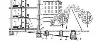
The entire sewerage complex of a residential building is called a utility-fecal, or utility-household, and is designated in design and regulatory literature as sewerage K1.
This network unites plumbing receivers, such as bathtubs, sinks, sinks, toilets, bidets, etc., used for sanitary and hygienic purposes. Receiving devices are used, such as funnels, trays, ladders, and sewer pipes connecting them.
A mandatory part of plumbing fittings is a hydraulic valve. This is a U-shaped siphon half filled with water. This simple technique creates a water barrier that prevents gases from flowing back into the room. Toilets and drains are structurally made with valves; they are connected to other appliances after the drain holes.
Plumbing receivers are connected to outlets through which household wastewater enters the sewer network.
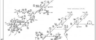
Sewage scheme K1
The pipeline part includes horizontal sections laid with a slope. They flow into risers - vertical sections that combine drains and lead them to the collector. The connection of various sections is made using shaped parts that ensure a change in the direction of the pipelines and their deflection.
A collector is a pipeline laid horizontally with a large slope, connecting the sewage system of a building with the complex of a populated area.
Ventilation piping is an essential part of the plumbing system. They run vertically and are connected to the drainage system. Ventilation helps stabilize the pressure in the sewer system. When designing drainage in small areas, drainage ventilation is provided by air draft, which is a consequence of heating the risers by the internal heat of the premises.
For the installation of a household drainage network, different types of pipe products can be used, the use of which is regulated by SNiP. In the case of waste disposal by gravity, cast iron, asbestos-cement, concrete, reinforced concrete, plastic, and glass pipes are recommended.
When implementing pressure discharge, cast iron, reinforced concrete, plastic or asbestos-cement pipes can be used. For the ventilation part, in addition to cast iron, SNiP allows the use of asbestos-cement pipes, polypropylene, and PVC pipes.
Sections of Ø 50 mm are used as outlets from appliances other than the toilet. Toilet outlets are made with Ø 110 mm. The dimensions of the elements of the entire network are determined by calculations carried out during the design of the sewer system.
Sewer K1 has its own outlet, which is arranged at an angle of 90⁰ to the outer walls, buried to a level slightly higher than the base of the foundation. If there is a basement, the release is performed above the basement floor.
The building's sewerage system is connected to the public sewer system. In the case of a country cottage, it is possible to organize a shambo sewer system, when waste is discharged into a receiving pit on the site and is periodically pumped out and removed. In this case, you should organize vehicle access to the drainage pit.
Compliance with all standards and high-quality installation of household wastewater disposal is a guarantee of reliable operation of the entire wastewater disposal unit.
Application in everyday life
Most people do not encounter topographical surveys in everyday life. Most often, the task of reading, deciphering and drawing up such maps falls to cartographers and builders, and topographic surveys of utility lines are considered the most popular.
Symbols of utility networks on topographic surveys are a prerequisite for their objectivity. This includes telephone networks, water supply, power lines, gas pipelines and other communications.
Symbols on topographic surveys of utilities are carried out in a linear way - straight solid or dashed lines:
- all above-ground operating pipelines and communications are indicated by a straight solid line 0.3 mm thick;
- all project, damaged or inoperative overhead communications are indicated by a dotted line 0.2 mm thick;
- all underground communications are indicated by a dotted line.
At intersections with other objects or communications, near the frame (at least every 5 cm), a letter designation that characterizes the transported material (product) is integrated into the line indicating the utility communications.
The letter determines the nature of communications:
- The letter G implies that the utility network transports gas; the designation of the gas pipeline on a topographic survey can be carried out with continuous (for above-ground) and intermittent (for underground installation) lines;
- B – water supply, whether the line will be continuous or intermittent, also depends on the method of communication;
- T – heating main;
- N – oil pipeline;
- K – sewerage.
Often, such information in topographical terms is presented as informatively as possible, indicating the pressure in the mains (gas), the material and thickness of the pipes, the number of wires and voltage in the power lines.
For this reason, an explanatory letter of lower case or numbers are often added to the first capital letter in designations.
For example, the designation Kl on a topographic survey means: storm sewer, in turn, a similar designation kb on a topographic survey will mean domestic sewerage.
Sewerage and water supply design
These systems play a very important role in people's lives. The comfort of the residents of the house, as well as the amenities of the premises, depend on how correctly the drawing of the sewerage and water supply is drawn up. Drainage systems play a special role. Some people believe that there is nothing complicated about installing a sewer system, but, in fact, drawing up its design is a very large, labor-intensive and responsible job. If you make even the slightest mistake, it will definitely show itself. Sometimes it comes to the point that design inaccuracies lead to the fact that the house turns out to be uninhabitable.
A sewer system is needed to remove waste liquids and some solid waste from each apartment. Most often they have very unpleasant odors, so the design of the drainage system is drawn up taking into account all the norms, rules of hygiene and improvement of residential premises. Solid elements, fats, and large amounts of storm water pass through the sewer system. This suggests that the system must be reliable in order to efficiently fulfill its main purpose throughout the entire established period of operation.
But no one is protected from force majeure situations. Therefore, the sewerage project must be designed in such a way that in the event of unforeseen circumstances and any breakdowns, everything can be quickly corrected.
The drainage system is very important for any house - both multi-storey and private. Its task is to discharge wastewater into special reservoirs. It is very important to design the system so that contaminated liquids do not enter the ground. Otherwise, there may be a threat of sanitary and epidemiological danger throughout the surrounding area.
Designing a water supply system is an equally complex and very responsible task.
They also have their own rules and regulations. Most often, the water supply and sewerage system is designed at the beginning of construction of the building. But it also happens that it is necessary to supply water and drainage in an already completed house. Most often, this occurs in the old fund and in the private sector. When drawing up such drawings, there are some peculiarities. For each case, decisions are made individually.
It is worth noting that even in the simplest at first glance case, there are a lot of nuances that must be taken into account. Therefore, when drawing up a drawing and project of water supply and sewerage for a residential building, it is worth turning to professionals. Specialists know exactly how to properly and safely provide water to your home and remove waste water from the premises.
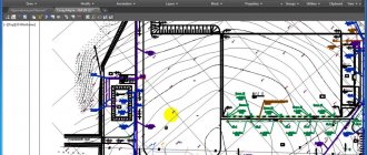
Design of utility networks in topographic survey
Often the question “how are sewers indicated on a topographic survey” implies an interest in the color of the lines. There is a lot of controversy regarding the color of communications on topographic surveys. On the one hand, there is a special manual: “Rules for drawing symbols on topographic plans of underground communications on scales 1:5000 ... 1:500” Moscow, “NEDRA” 1989.
The handbook states that all signs are painted in black, and even prescribes the recommended thickness of these lines. At the same time, the reference book allows “for greater clarity” to convey the lines in a different color.
Liquid properties
Liquids are those substances that are in a liquid aggregate state. It, in turn, is intermediate between the solid and gaseous states of aggregation. The liquid also has a property that is not found in any other state of aggregation: it is capable of changing its shape under the influence of tangential mechanical stresses within almost unlimited limits. In this case, mechanical stresses can be very small, and the volume of liquid remains unchanged.
Another important property inherent in all liquids is surface tension. Neither gases nor solids have it, but it is explained by the following reasons: due to the fact that the balance of forces acting on the surface molecules is disrupted, a certain new resultant force appears, directed into the substance. This is precisely what explains the fact that the surface of a liquid is always “tensioned”. If we consider this situation from the point of view of physics, then it can be argued that surface tension is nothing more than the force due to which the molecules of a liquid do not move from its surface to the deep layers. It is the force of surface tension that explains the shape of falling drops of any liquid.
Free library of regulatory documentation
The generally accepted ones are:
- the designation of the water supply system on the topographic survey is in green;
- the designation of the sewerage system on the topographic survey is in brown;
- gas pipelines - in blue;
- heating networks - in blue, etc.
Often in practice there are discrepancies between the designations on the topographic survey and the general plan - the colors of communications are drawn with lines of different colors. Thus, the designation of a communication cable on a topographic survey, according to cartography standards, should be black, but in general plans, for convenience, it can be drawn in yellow, red or another color convenient for visualization.
Power supply and communication cables are designed as follows:
| Standard cable designation for topographic surveys |
| To distinguish between existing and project lines, additional markers are used |
| Designed network |
| Active line |
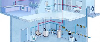
What does the water supply and sewerage diagram contain?
When drawing up a project, you need to take into account a lot of different points. Here, as a rule, not only the layout diagrams of various components, pipes, valves and traps are indicated, but also a considerable amount of other information important for the performers. It is necessary to make it easier and more convenient for craftsmen to read the drawings. Conventions are used here, but mainly in alphanumeric form.
The design documentation must contain a communications layout plan, namely hot and cold water supply and sewerage systems. Well table data, project specifications and a lot of other information are indicated that may be useful during the execution of the planned work. Only with the correct preparation of all documents can you be sure that the system will function correctly and will not cause inconvenience to the people who will live in the designed building. It will be impossible to cope with this task without certain knowledge and experience, therefore, if you have doubts about your own abilities, you should entrust this work to professionals.
Information about the designation of the sewerage system and water supply is usually included in project documents using alphanumeric symbols. They are common to all plumbing piping diagrams and drawings.
The general designation of the water supply system is marked as B0, pipes for domestic and drinking water will be registered as B1. If the diagram shows a water supply for the fire-fighting system, then B2 is indicated, and water for production needs is supplied through pipe B4.
Thus, everything that has o relates to the water supply system. The sewer sign is marked with the letter “K”. If the diagram needs to indicate a household drainage system, K1 will be indicated. For rainwater drainage, the symbol K2 is used. To create a drainage system in an industrial building, mark K3 will be used.
All numeric, alphabetic and graphic symbols must be used correctly. It is not allowed to use in water supply and sewerage drawings those elements that are not regulated by GOST and SNiP. It must be remembered that with the help of appropriate signs a formula is created according to which the performers then work. If you write the diagram and draw up the drawing incorrectly, this can lead to excessively rapid wear and tear of the network, frequent breakdowns, or even make the building unsuitable for human life. Correct symbols and conventions guarantee that the contractor will read the document as expected, and the quality of construction and installation work largely depends on this. If all GOST requirements are met, it is possible to develop an effective sewerage and water supply system, which will guarantee their long and uninterrupted operation.
Additional signs and explanations
With the help of topographical surveys, all the nuances of the area are displayed on paper: from natural caves to completely man-made gas stations, so to complete the picture, graphic elements are combined with letter ones. Decoding a topographic survey is considered objective only if all the elements “signs plus letters” are taken into account. Some elements, such as the designation of wells on a topographic survey, can be presented in several versions.
Letter symbols on topographic surveys often give schematic images a new meaning, for example, an ordinary rectangle will simply indicate non-scale residential buildings - only complete with letter explanations does the map make sense. So, the designation on the topographic survey TP inside this rectangle will mean that the building is a transformer substation.
Storm sewer K2
To remove rainwater, a storm drainage system is installed - K2. It represents a plumbing system of funnels, gutters, pipes, filters for purifying wastewater from sand. Open type structures are most often used. Drainage is carried out using open gutters or channels.
Sewage scheme K2
They transport water flows to the underground part of the complex. For drainage, PVC pipes are used, including corrugated pipes with a smooth inner surface, and asbestos-cement pipes.
Properly arranged and designed in accordance with technical regulations, K2 sewerage will protect the building from subsidence and cracking of walls. Upon completion of installation, the system must be tested by an organization that has the appropriate license.
Graphic elements
Conventional graphic symbols on topographic surveys are used to reflect various phenomena and objects on the ground.
To people far from geodesy and cartography, many symbols on topographic surveys will seem like a meaningless set of geometric figures. This should include symbols and a coordinate grid.
Two types of coordinates are accepted on topographic plans or maps:
- rectangular;
- geographical.
Coordinates give specialists information about the exact distance between objects.
Classification of conventional signs
On maps and plans, all terrain elements are indicated by symbols. They are usually divided into 3 independent groups:
- scale or outline;
- off-scale;
- explanatory.
In order to make the depicted signs more visual, all elements of the same type are painted with the same paint, i.e., any hydrographic element is indicated in blue.
Objects of the same type on maps with different scales are indicated the same way and differ only in size. The larger the scale of the map, the more objects can be plotted and information indicated on it. Small structures of secondary importance, as a rule, are not depicted on them, thereby increasing the clarity of the image.
This technique is called cartographic generalization. Filling a map or plan with terrain elements depends on the characteristics of the territory. The more complex it is and the more saturated with objects, the more elements will be applied to the plan and the more difficult it will become to read. An area that is replete with lakes, rivers and other bodies of water is topographed without small features unless they are major landmarks. For example, in such terrain, wells are not of significant importance, but in steppe areas they must be marked on the plan.
Along with elevation marks, they are good reference points. In desert areas, the main source is indicated by a larger icon, and explanatory inscriptions are placed next to it. To the left of the symbol, the ground level is indicated in black font, and to the right is the depth of the source in meters and the filling capacity in l/hour.
When taking a map of the area in populated areas, water supply, sewer and gas systems must be identified. At the locations of water supply and sewer wells, the diameters of the pipes, the direction of movement of the medium and the type of structure are indicated. In gas wells, in addition, the pressure in the pipelines is relieved. In addition to these structures, gas distribution points must be designated with appropriate explanations.
In addition, on the ground, the distance of the underground pipeline from buildings and other objects is marked on special signs. This sign is applied to electrical poles, fence posts, etc., indicating the direction and distance of the pipe from a specific landmark.