Scope of application and benefits
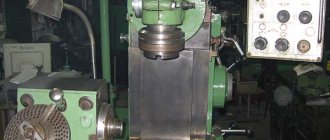
In addition to milling equipment, the rotary table is installed on drilling, boring and other machines, the table of which, together with the part, moves only in a horizontal or vertical plane relative to the spindle with the cutting tool.
The rotary table allows you to process workpieces on a milling machine along the contour, creating a complex configuration, spiral grooves, grooves and holes. Depending on the type of rotary table, the machine can cut grooves into the part at any angle to the base surface, drill and bore holes without reinstalling the part with an accuracy of tenths or even hundredths of a degree.
Using a rotary table on a milling machine offers the following advantages:
- milling of the top and side surfaces;
- creating polyhedra from one installation;
- drilling around the perimeter and at an angle to the table surface;
- Boring on all surfaces is straight and at any angle;
- creating spiral grooves on the surface of the part;
- cutting grooves of any configuration.
The rotary table allows you to process complex parts on a milling machine from one installation.
Important!
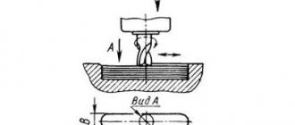
When the table rotates automatically, rotating bodies, such as rings and cylinders, are made by milling - high-performance roughing.
LONGITUDINAL AND TRANSVERSE TABLE MG-2A with a rotating base.
The longitudinal-transverse table with a rotating base MG-2A is a multifunctional accessory for a wide range of applications, mainly on milling, drilling and other machines. The use of longitudinal and transverse movement together with rotation around the base makes it easier and faster to process parts.
l
TECHNICAL CHARACTERISTICS OF TABLE WITH ROTARY BASE MG 2A:
| MG-2A | |
| Table size, mm | 254x444 |
| Amount of longitudinal movement of the table, mm | ± 114 |
| Amount of lateral movement of the table, mm | ± 76 |
| T-slot width, mm | 15.875 |
| Distance between T-slot, mm | 80 |
| Minimum readable dial value | 0.001” |
| Maximum permissible weight of the workpiece relative to the center of the table, kg | 250 |
| Maximum permissible force relative to the center of the table, N | 7000 |
| Surface deviation along the length of the table, mm | 0.03 (-) |
| Permissible deviation of perpendicularity, mm | 0.03/100 |
| Parallelism of the table surface to the base surface, mm | 0.05 |
| Permissible deviation when rotating the table 0-360°, mm | 0.08 |
| NET WEIGHT, kg | 70 |
| GROSS weight, kg | 90 |
| Packaging dimensions, mm | 600x600x265 |
| PRICE for cross table MG-2A, rub. | 40 100 |
Classification
Rotary tables are classified according to different parameters:
- the location of the grooves is radial and parallel;
- number of rotation axes: one or two perpendicular;
- dimensions - standardized sizes;
- faceplate rotation drive is manual and automatic.
For mass production, devices with expanded functionality are used, combined with a dividing head, and complex designs for CNC machines.
Round
The simplest design of a rotary table. The workpiece rotates around an axis located vertically.
The device allows you to process side surfaces, create polyhedra, chamfer and make grooves and boring.
Reference! The simplest design of a rotary table. You can do it yourself at home.
Vertical-tilt
The table rotates around its axis and tilts 45⁰ in a perpendicular plane. Used for milling complex reliefs, drilling and boring holes at an angle to the base. The device provides high accuracy of the spatial location of holes.
Used on milling and drilling machines.
Vertical-tilt with rotating disks
The rotary disks included in the turntable set are used as a dividing head. Usually there are 3 of them. with different hole ratios. They mechanically rotate the workpiece to a certain angle in accordance with the number of teeth. The use of devices allows you to cut gears and gears with straight and oblique teeth.
Horizontal
The surface of the faceplate is located in the plane of the Z axis. The device allows for circular milling, processing of ledges, grooves, and boring.
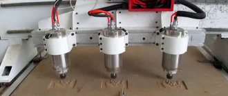
With vacuum grip (for CNC units)
On CNC machines, pneumatics are used to quickly fix and center the part. The fastening is tightened by vacuum when air is pumped out. The compressor turns on automatically according to the program. If necessary, the workpiece quickly changes its position, being clamped into the spindle chuck and vice versa.
Important!
Pneumatics are also used to fasten workpieces made of thin sheets, aluminum, and non-ferrous soft alloys, which are deformed when the bolts are tightened.
Equipment classification
It is customary to divide rotary tables according to several parameters. Firstly, in terms of working position. The equipment can be horizontal, vertical and universal, that is, it can work in two planes.
Secondly, in terms of size. The size of the faceplate is taken into account. It can vary from ∅ 110 mm to ∅ 630 mm. Tables of other sizes are possible, but these are special products made to order or for specific operations.
Thirdly, according to the method of adjustment and configuration. The equipment can be equipped with a simple mechanical handle, driven by the main machine and equipped with its own electric motor.
And finally, fourthly, a rotary table with expanded functionality. For example, it may have not one axis of rotation, but two, vertical and horizontal.
Tools that expand the capabilities of metalworking equipment
The milling machine work table moves linearly in 2 or 3 directions. The rotary table rotates the workpiece, turning it towards the spindle with the cutting tool, different faces and tilting it at an angle. This allows you to perform several operations from one installation, and more accurately maintain center-to-center dimensions and the distance from protrusions and grooves.
Sinus
The sine table is highly accurate. Rotates with an accuracy of one second. Helical gears and spiral grooves are installed due to the synchronous rotation of the faceplate and its tilt at an angle. For manual control there is coarse and fine adjustment, 2 dials for each movement.
For drilling machine
Overhead rotary tables are installed on the drilling machine table with a radial arrangement of holes. Uniform rotation of the part allows the drill to make holes at an equal distance from the center of rotation, eliminating constant rearrangements. A table with an inclination of up to 45 degrees is designed for drilling at an angle to the surface of the part.
Round, magnetic
Magnetic electric coils are excited when current is applied to them, several times faster than conventional mechanical fastening. The part lying on the working surface is instantly attracted or released. The machine operator does not have to turn the screws or wait for them to be mechanically tightened. This prevents overtightening of the bolts.
The advantages of a magnetic table are the quick fixation of parts without dents or deformations. The disadvantage of installing in a limited number of materials is that only carbon and alloy steels are magnetized.
Reference! Non-ferrous alloys, stainless steel, aluminum and copper cannot be fixed on a magnetic table.
ROTARY TABLES HORIZONTAL-VERTICAL TK13EL, CNC.
Horizontal-vertical tables with a through hole in the spindle of the TK13EL CNC series are an excellent solution for using them on CNC milling machines and machining centers. They are used in combination with the machine's CNC controller or with an independent controller on non-CNC machines. To ensure work with a wide range of applications, there is a faceplate with a through hole, as well as other devices that allow you to fix the part between the table and the tailstock. With their help, operations can be performed particularly accurately. The presence of a through hole in the spindle allows the use of hydraulic (pneumatic) powered collets and chucks when processing long shafts and other products.
TECHNICAL SPECIFICATIONS OF TK13EL, CNC:
| TK13200EL | TK13250EL | TK13315EL | |
| Faceplate diameter, mm | Ø210 | Ø250 | Ø315 |
| Center height, mm | 140 | 160 | 210 |
| Diameter of passage hole, mm | Ø60H6 | Ø70H6 | Ø90H6 |
| Width of the fixing groove-key, mm | 14 | 18 | 18 |
| Width of fixing T slot, mm | 4-12 | 6-12 | 6-12 |
| Worm gear ratio | 1:90 | 1:90 | 1:90 |
| Gear ratio | 1:90 | 1:180 | 1:180 |
| Maximum rotation speed, rpm | 16.6 | 11.1 | 11.1 |
| Table rotation angle per pulse | 0.001″ | 0.001″ | 0.001″ |
| Servo drive power, kW | ≥0.9 | ≥1.0 | ≥1.0 |
| Servo drive torque, Nm | ≥3 | ≥5 | ≥5 |
| Division accuracy | 30″ | 30″ | 30″ |
| Positioning stability | 8″ | 6″ | 6″ |
| Clamping force at oil pressure 15x105Pa, Nm | 450 | 1000 | 1800 |
| Clamping force at air pressure 5x10⁵Pa, Nm | 150 | 300 | 500 |
| Max. weight of the workpiece in a horizontal position, kg | 200 | 250 | 350 |
| Max. workpiece weight in vertical position, kg | 75 | 150 | 175 |
| Maximum torque, Nm | 90 | 300 | 700 |
| NET WEIGHT, kg | 75 | 110 | 200 |
Certified models
The presence of a certificate indicates that the product meets all standards and safety requirements. Only after checking the list of characteristics, a quality certificate is issued. Such models include the following.
PROMA OS-250 250001
Used for milling, drilling, threading.
Characteristics:
- installed vertically and horizontally;
- rotation angle 360⁰;
- T-slots 6 pcs.
Installed on small milling machines for the production of single parts and small batches.
Homge HUT-300 universal
Tilt angle 90 degrees. Installation of the workpiece is simplified due to the presence of 2 locking bolts.
TSK 200 tilting rotary table
Used for circular milling, boring, creating corners and complex configurations.
Characteristics:
- rotary table with an inclination of up to 45⁰;
- mechanical control;
- high processing accuracy.
In addition to these devices, Vertex, Encore Corvette, Purelogic R&D products and many others are certified.
ROTARY TABLES HORIZONTAL TS (160-1250 mm).
TECHNICAL CHARACTERISTICS OF ROTARY HORIZONTAL TABLES TS:
| TS 160A | TS 200A | TS 250A | TS 320A | TS 400A | TS 500A | TS 630A | TS 800A | TS 1000A | TS 1250A | |
| Faceplate diameter, mm | Ø160 | Ø200 | Ø250 | Ø320 | Ø400 | Ø500 | Ø630 | Ø800 | Ø1000 | Ø1250 |
| Center hole taper | KM2 | KM3 | KM4 | KM5 | KM6 | — | ||||
| Hole diameter, mm | Ø25x6 | Ø30x6 | Ø40x10 | Ø50x12 | Ø75x14 | |||||
| T-slot width, mm | 10 | 12 | 14 | 18 | 22 | |||||
| Angles of convergence of T-slots | 90° | 60° | 45° | |||||||
| Fastening groove width, mm | 12 | 14 | 18 | — | — | — | — | — | ||
| Worm and worm gear modules | 1.5 | 1.75 | 2 | 2.5 | 3.5 | 4.5 | 5.5 | 5 | ||
| Worm gear ratio | 1:90 | 1:120 | 1:180 | |||||||
| Graduation | 360° | |||||||||
| Rotate the table with one turn of the worm | 4° (1′ division) | 3° (1′ division) | 2° | |||||||
| Minimum scale value | 10 « | |||||||||
| Reading accuracy | 80″ | 60″ | 30″ | |||||||
| Maximum workpiece weight, kg | 100 | 150 | 200 | 250 | 300 | 550 | 700 | 1250 | 2000 | 3000 |
| Weight, kg | 16.5 | 22.5 | 33.5 | 65 | 125 | 215 | 345 | 800 | 1300 | 1900 |
| Price, rub. | 25 700 | 28900 | 30 900 | 42 300 | 65 100 | 125 500 | 290 000 | 592 300 | 938 500 | 1 573 000 |
DIMENSIONS OF ROTARY TABLES HORIZONTAL TS:
| TS160A | TS200A | TS250A | TS320A | TS400A | TS500A | TS630A | TS800A | TS1000A | TS1250A | |
| A | 260 | 290 | 330 | 410 | 530 | 640 | 820 | 1000 | 1170 | 1400 |
| B | 196 | 236 | 286 | 360 | 450 | 560 | 700 | 890 | 1080 | 1300 |
| C | 332 | 369 | 422 | 493 | 612 | 753 | 898 | 1080 | 1295 | 1420 |
| D | Ø160 | Ø200 | Ø250 | Ø320 | Ø400 | Ø500 | Ø630 | Ø800 | Ø1000 | Ø1250 |
| G | 12 | 14 | 18 | 22 | 22 | — | 22 | |||
| H | 75 | 80 | 90 | 110 | 140 | 158.5 | 160 | 215 | 250 | 283 |
| J | 12 | 14 | 18 | 22 | 30 | — | 30 | |||
| K | 76 | 91.25 | 102.5 | 128.5 | 180 | 230 | 295 | 364 | 364 | 487.5 |
| L | 194 | 211 | 241 | 273 | 337 | 393 | 468 | 535 | 654 | 690 |
| M | KM2 | KM3 | KM4 | KM5 | KM6 | — | ||||
| P | 27 | 27 | 30.5 | 44 | 60 | 65 | 68 | 76 | 106 | 116 |
| Q | 125 | 160 | 180 | 220 | 250 | |||||
| d | Ø25 | Ø30 | Ø40 | Ø50 | Ø75 | |||||
| h | 6 | 10 | 12 | 14 | ||||||
Homemade tilt-rotary machine for metal and wood machines
In a home workshop where there is a milling machine, it is good to have a rotary table among the devices. They are sold in stores if you need to make a lot of parts. Hobbyists can make the device themselves.
Required tools and materials
The easiest way to make a device yourself is from a lathe chuck. To do this you will need the following tools:
- screwdriver;
- Bulgarian;
- hex and socket wrenches;
- welding machine.
The rotary table consists of parts:
- scroll chuck;
- base with 2 ears;
- limb from the drawing board;
- clamps;
- bolts;
- 2 disks.
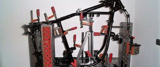
Ears with holes for bolts are welded to the base for fastening to the working surface of the machine. The limb is installed between 2 washers above the base. An inspection window is cut out in the body of the cartridge to see the divisions. The part is clamped into the jaws and rotated manually.
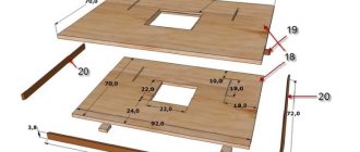
Drawings and calculations: When making a device yourself from scrap materials, a calculation is made of the stroke of the worm shaft and the number of teeth on the disk through its radius. Then a tap with the required pitch for cutting the disk is selected.
Step-by-step instruction
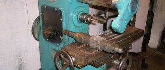
The disk is fixed on the workbench and put on the axle. Fasteners are installed. A screw is screwed in near the edge, against which the tap inserted into the electric drill rests. On its side it rests against the surface of the disk. When rotated, it cuts the tooth. The worm is installed in the housing in engagement with the cut teeth on the disk. A dial with a handle is attached to its end. Everything is attached to the base.
Safety precautions
When making a device, it is necessary to check the condition of the tool and the wires of the electric drill and welding machine, the grounding of the equipment and sockets. Even in a home workshop, you should wear overalls with long sleeves and safety glasses. The workplace must be cleared of unnecessary objects and well lit.
A rotary table for a milling machine increases the functionality of the equipment and allows you to make more complex parts with less time. For home use, you can make the device yourself.
REAR STOCK ADJUSTABLE WZK.
Adjustable rear headstocks WZK are designed for use with vertical rotary tables. They are used to hold and center cylindrical and other parts during machine processing. The height of the center and the angle of inclination can be changed and adjusted as needed. The design allows the center to be pulled inward to perform part changes and repeat the operation. For safe operation, the center is fixed with a clamping handle.
TECHNICAL CHARACTERISTICS OF WZK TAILSTOCKS:
| WZK140 | WZK180 | WZK224 | |
| Applicability | TSL160 | TSL200, TSL250 | TSL320 |
| Height from base MIN to center MAX | 100 140 | 140 180 | 180 224 |
| Center cone | KM | KM2 | |
| Fastening groove width, mm | 14 | 18 | |
| Center inclination angle, degrees. | +/- 11 | ||
| Center displacement, mm | 25 | ||
| Dimensions, mm | 284x230x194 | 353x308x223 | 398x308x223 |
| Weight, kg | 8 | 14,5 | 16,5 |
| Price, rub. | 6 500 | 6 900 | 7 600 |
| Designation | A | B | C | D | E | F | G | H | I | J | K | L | M | N | O | P |
| WZK140 | 169 | 34 | 50 | 45 | 18 | 110 | 140 | 100-140 | 18 | Ø14 | 14k7 | 162 | 98 | 20 | Ø18H7 | — |
| WZK180 | 281 | 36 | 87 | 80 | 38 | 130 | 172 | 140-180 | 28 | Ø14 | 14k7 | 200 | 125 | 24 | Ø28H7 | KM2 |
| WZK224 | 281 | 36 | 87 | 80 | 38 | 130 | 178 | 180-224 | 28 | Ø18 | 18k7 | 210 | 125 | 28 | Ø28H7 | KM2 |