An external water supply system is a complex of networks, structures and equipment designed to supply water to the consumer from a source or centralized communications. An additional task is to bring fluid parameters to standard values. To protect against freezing, most of the elements of the external system are underground.
Our company carries out comprehensive work on laying and installing external water supply systems. We provide assistance in coordinating excavation work and connecting to networks. Fast, high quality, inexpensive!
Call! ☎️
Types of water supply systems
Depending on the purpose, external water supply can be divided into several types:
- External water supply of a private building. Usually it is a section of the network from the source of water supply (well or borehole) to the house. Its features are the laying of pipes at a sufficient depth, although it is also possible to use heating of the water supply using electric cables and draining water during the period of non-use of the system.
- System for a detached apartment building. Usually it is a water supply from a well to a centralized network to consumers. A special feature of the network is the installation of a common water meter for the entire building.
- Water supply for a complex of buildings. It is distinguished by the presence of separate pipes for domestic and drinking water supply and fire-fighting water supply.
- Outdoor system for an industrial enterprise. It includes not only fire-fighting and drinking water supply, but also industrial water supply.
The degree of purification of water supplied to consumers depends on the type of system. In the domestic drinking water supply it must be of drinking quality; in the fire-fighting and irrigation water supply, technical liquid is usually used. To meet production needs, water can undergo either a full or partial purification cycle, including clarification and softening.
Pipeline installation methods
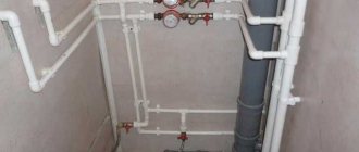
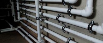
Polyethylene pipes can be connected to each other using a special soldering iron by welding or crimp fittings. The soldering iron guarantees a reliable connection and after assembly, all pipes will form one solid product. Most often, welding work is carried out on the surface. The pipes are combined into sections, which are then lowered into the trench and welded using the same method. They do this because it is more convenient to perform welding work on the surface.
Laying of polypropylene analogues can also be done by welding. But unlike polyethylene, in order to connect polypropylene pipes, the soldering iron must be heated to a temperature of 260-270 degrees. When performing welding work, the heating time must be observed. If the pipe diameter is 25 millimeters, then the joint must be heated for approximately 9-10 seconds. If the diameter is 32 millimeters, you need to heat it a few seconds longer. Temperature loads must be observed; overheating will damage the surface of plastic products.
Low heating of the connecting parts is also considered a gross mistake; the connection will not be strong and a leak may form in these places. The inner surface of the connecting fittings and the outer surface of the pipes must be cleaned of dust and moisture, otherwise the quality of soldering may deteriorate. During operation, plastic smears appear, which do not need to be removed immediately, since you can accidentally deform the heated pipe. Even if you follow the soldering technology, you should not immediately fill up the constructed pipeline. First you need to pressure test it for a few days. If no leaks have appeared during this time, then everything is securely connected to each other and the trench can be filled up.
Composition of the external water supply system
The list of external water supply elements depends on the source of water supply. However, most of the devices and equipment are the same for both autonomous and centralized systems.
The main elements are considered:
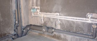
- Pipes and fittings . For external water supply, steel pipelines and connecting parts are often used. If the water pressure is high, the pipeline can be cast iron, and for supplying water from an autonomous source to a private house, it can be copper.
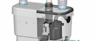
- Pumps and pumping stations . They provide a sufficient level of pressure in the system and usually operate in automatic mode.
- Armature . It can be shut-off and regulating. Water-folding elements such as taps are part of the irrigation system, and hydrants are part of the fire water supply system.
- Wells . Must be located in areas where fittings and fittings with flange connections are installed. The well consists of a working chamber and a descent. It is not allowed to install a water supply system, even an autonomous one, without inspection wells.
The availability of a water treatment system depends on the quality of the supplied water. When used as sources and wells, the removal of mechanical impurities is ensured by coarse filters. Equipment for removing chemical and biological contaminants is usually installed inside a building and already belongs to internal water supply systems.
Types of local water supply networks
Taking into account the type of system being installed and the method of its installation, delivery of drinking water in different containers is allowed. This water supply option is considered temporary, until the permanent water supply network is completed.
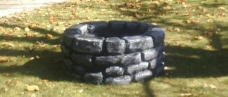
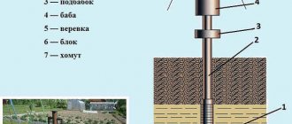
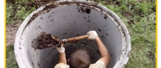
Since water lies at different depths, preparatory work will be required to “extract” it. To bring it to the surface and use it for personal purposes, experts recommend building a well or well.
If a well is used as a permanent water supply, you will need to dig, removing liquid from the surface layers of the soil. Such waters are distributed unevenly. They can flow along the contour of the earth's surface or lie at different depths.
The water supply method under consideration is inexpensive to install and operate. Its disadvantages include seasonal filling of the well, if during the digging process you get to the lower or upper section of the groundwater flow. On a flat area, the well will fill regardless of the season and weather conditions.
To simplify the process of operating the well, a submersible or surface electric pump is used. He lifts and delivers water to the house. In this case, you can collect water with a bucket.
To construct such a system, different pipes are used. The well itself is constructed as a monolithic structure equipped with a lid. You can make it from a log or special rings.
It is possible to equip an external water supply network by drilling wells of various capacities:
- at the dacha, the approximate liquid consumption is 2 cubic meters per hour;
- in a house with permanent residence, the approximate consumption is 3 cubic meters per hour.
Before drilling begins, you will need to obtain permission for the work being carried out. Groundwater is a strategic reserve of the country, which is protected by the legislation of the country. The received passport for the well contains technical information, including the diameter of the well. Upon completion of installation work, the water is sent to the laboratory for testing.
Gasket features
External system pipes can be laid in different ways:
- on overpasses and supports (with mandatory insulation);
- underground in trenches, for digging which, depending on the diameter of the pipeline, special equipment or manual force is used;
- underground using a trenchless method.
The depth of installation of pipes for an external water supply system is selected depending on the level of soil freezing in a given region. In the central part of the country, it is recommended to lay the water supply system 1.6-1.8 m underground. In the southern zone this depth can be 1-1.5 m, in the northern zone - up to 3 m or more. The requirements are the same for external water supply in private houses and for centralized water supply.
The trench for laying pipes usually has a trapezoidal cross-section with a base at ground level. Its width should be at least 50 cm at the bottom and 80 cm at the top. The trench is laid with a slope of 5 degrees towards the source. If there is insulation, pipes can be laid to a shallower depth. Summer pipelines used at the dacha do not need to be insulated, but when preparing the external system, water must be drained from it.
For external water supply, insulation is required. For this purpose, special cylinder insulation or rolled heat insulators are used. It is allowed to use shell thermal insulation, which has a high level of tightness. The use of rigid insulation such as polystyrene foam or expanded polystyrene is not recommended.
General and individual requirements for pipelines
Like any construction project, the external water supply pipeline is installed in accordance with the project, which in this case is briefly referred to as PPR.
Laying and connecting pipes
Work on laying and connecting pipes begins after the compliance of the dimensions of the trenches, their bottom marks and the strength of the walls has been checked. If this is a main water supply pipeline, the installation of which is carried out above ground, then the strength of the structures on which the pipes will rest is checked. The results of all checks must be recorded in the PR (work performance) log.
Ground laying of pipelines
- The slope of water supply pipelines is very important for non-pressure systems, and is calculated during their design process. In such water supply systems, socket-type pipes are usually used, and one of the main requirements for their installation is their laying along a slope with the socket up.
- Where the project provides for strictly straight sections, between adjacent inspection wells they are viewed using a mirror. If the visible circle is not deformed, then the pipeline is straight. Deviations in the shape of a circle are allowed only horizontally, no more than 5 cm in one direction or another.
- By the way, not so long ago a laser device appeared, with the help of which the straightness of cylindrical channels is monitored in a non-contact manner. You can see it in the photo below. The check is carried out twice: immediately after laying the pipes, and then after filling the trenches.
Device for testing cylindrical threaded pipes with a diameter of 55 mm or more
- On straight sections of the water supply route, the ends of the joined pipes must be centered so that the width of the gap in the sockets is uniform around the circumference. As for the axes of the pressure pipeline, their displacement should not exceed 10 cm from the position provided for in the plan of the water supply pipelines. Vertically, the maximum permissible deviation is only 3 cm.
- When pipelines are laid along a curve and no shaped elements are used, then for socket pipes joined on rubber seals, the angle of rotation at the joint should not exceed 2 degrees. If their diameter exceeds 600 mm, then this tolerance is halved.
- To avoid clogging of the pipeline, during breaks in installation, it is recommended to close the holes in the pipes and shut-off valves with plugs (plugs). When joining pipes, sealants and sealants must be used to connect them.
Plastic plug for pipe
Since the material of water supply pipelines varies, the methods of connecting the pipes are also different. This can be a threaded connection, welded (butt or socket), with union nuts or flanges, which have special requirements.
Note! It is very important to ensure that the flanges are perpendicular to the pipe. The flange planes must not have any curvature, and all fastenings must be made on one side. When tightening the bolts, you should not follow the sequence - it must be done in parallel, crosswise. The tightening force must be the same. If the flange is skewed when making fastenings, it cannot be aligned by tightening the fastenings.
What works are activated
Since underground water supply pipelines are covered with soil, all stages of their construction must be documented in hidden work reports.
Here is their main list:
- work related to foundation preparation;
- measures to protect pipes and fittings from corrosion;
- methods of sealing joints;
- construction of wells;
- sealing pipe entries into enclosing structures;
- fastening of water supply pipelines;
- backfill with compaction.
In this chapter we have described the requirements that are common to all types of pipelines. Below, brief instructions will be given for each type separately.
Input of external water supply into the building
The following methods are used to introduce pipes into a building:
- They run the pipelines through the foundation by drilling a hole in the concrete. To simplify the work, it is recommended to provide the input in advance, at the stage of manufacturing the strip or monolithic base.
- Pipes are laid between the supports of a columnar or pile foundation. The turn when entering the building must be insulated.
If it is impossible to make a hole in the foundation, another entry method is used - laying under the base. To do this, it is recommended to use a piece of pipe of larger diameter, which is buried under the building. There is running water inside it.
Pipe filling calculation
Filling - the ratio of flow depth to the internal diameter of the pipe (h / d) - can be complete or incomplete (expressed as a dimensionless number from 0.1 to 1.0 or as a percentage).
The sewer pipeline is often designed for free-flow operation with a partially filled cross-section (maximum 0.95). A reserve in the cross-section of a closed channel is needed to pass a flow rate exceeding the calculated one for ventilation.
The flow rate is also important, which will not allow the formation of indelible deposits.
The calculation of sewer pipelines is carried out by assigning a speed of movement of the waste liquid (v) of at least 0.7 m / s, filling - at least 30%, and so that the condition is met:
- v ∙ (h / d)-2 ≥ 0.5 - for plastic, fiberglass;
- v ∙ (h / d)-2 ≥ 0.6 - for other materials.
If the water flow is so small that it is impossible to fulfill this condition, then the calculated slope for a sewer with a diameter of 100 mm is assigned to 0.02. A smaller drop in meter markings is acceptable for larger diameters, but is not recommended.
The slope of an external sewer system of 160 mm in practice is taken to be no less than 0.02.
The filling, as a rule, turns out to be 0.35–0.4. At the highest design filling, the minimum speeds are:
- v min = 0.7 m/s - at d = 150–250 mm (h/d = 0.6);
- v min = 0.8 m/s - at d = 300–400 mm (h/d = 0.7).
Installation work
To lay the external pipeline and carry out all measures to protect it, you should contact professionals. By choosing the services of our company, the customer receives high quality work, strict adherence to deadlines and affordable prices. Our specialists help in obtaining permits and preparing other documents for the external water supply system, using special equipment and modern tools. If necessary, we will perform horizontal drilling, dismantle elements of the old pipeline and install inspection wells.
Call! ☎️
Minimum slopes of external sewerage
Wastewater received by the internal sewer system of the building (domestic, drainage) passes into the external one. The drainage in the building is discharged by gravity. The outlet lines of the yard network can also be pressure, but only if the terrain and soil do not allow creating the necessary slope of the pipeline (to create a flushing speed in particular) or if it is necessary to drain the basement.
The most important stage in sewer design is drawing up its diagram. Tracing comes down to drawing sewerage elements onto the plan of the sewer object: networks, septic tank (storage tank), wells, etc.
The solution to the scheme is individual for each case, since it is influenced by many local factors:
- configuration, size, object;
- the location of the street sewer or reservoir relative to it;
- terrain;
- ground conditions;
- sanitary requirements;
- economic considerations.
Usually the route is oriented in the direction of large slopes to local treatment facilities, or along the shortest path to the street sewer, parallel to the outer wall of the house, no closer than 3 meters from it.
If the slope of the area is insufficient, then increase the diameter of the pipeline. If the relief falls unevenly, a zone scheme may be required, in which runoff from an elevated area of the terrain is drained by gravity, and from a lower area by a pressure pipeline.
The gravity sewerage pipeline is straight. Only in wells (rotary) can you change its horizontal direction, slope and diameter.
Inspection wells (for cleaning and inspection of sewers) are installed both in straight sections, if their length reaches four to five tens of meters, and at the point of connection to the street network. They are made of brick, reinforced concrete, polymer materials, with a diameter of at least a meter, and are equipped with a tray connecting the pipes.
Connections of gravity sewerage pipeline parts:
- detachable bell-shaped;
- glued (seam pipes);
- welded (resistance welding), or on threaded metal connections (synthetic pipes).
The thermal elongation of the pipe is less if the water supply is pinched by the soil (due to friction). Temperature deformation is compensated by socket joints (with soft sealing rings). At the edge of the trench, permanent connections are preferred.
The trench along the bottom is made at least 40 cm wider than the diameter. A sand cushion (no thinner than 10 cm) is especially needed for dense, hard soils. The base can also be natural soil (undisturbed, dry during installation).
In order for a hollow horizontal cylinder to withstand greater pressure, it is important to organize a bed that follows its contour - so that it is in close contact with the ground along its entire length, at least a quarter of its circumference.
If the bearing capacity of the soil is weak (or if there is a risk that it will decrease), artificial foundations are needed:
- a layer of crushed stone, gravel, coarse sand 15–20 cm thick (with drainage trays in it) - in water-saturated soil, on a rock;
- pile foundation - in quicksand, peat bogs.
The backfill must be preceded by covering it with soft soil or sand, a layer no thinner than 0.3 m. The backfill is compacted with a hand tool - above the pipe, with a hand mechanized one - at the walls of the trench, every 10 cm.
Atmospheric water can be discharged together with domestic waste and separately - through trays, ditches, ditches. The semi-separated network contains spillway chambers. When rainwater flows are low, they are transferred to the domestic sewer system, and during a rainstorm, they are discharged into the street drainage system or reservoir.
The pipeline is insulated if it is located above the freezing depth: with slag, expanded clay, heat-insulating sleeves.
Documents regulating the installation of external networks
The main document according to which the installation of external water supply is carried out is SNiP No. 3.05.04/85.
In addition to this, it is necessary to take into account the provisions of the following collections:
- SNiP No.III/4/80;
- SNiP No. 3.01.03/84;
- SNiP No. 3.01.01/85;
- SNiP No. 2.04.02/84.
Ready communications must be accepted for operation in accordance with SNiP No. 3.01.04/87.
According to the standards, water pipes for external water supply and sewer analogues can be:
- asbestos-cement;
- steel;
- reinforced concrete;
- cast iron;
- ceramic;
- plastic.
Plastic pipes for external water supply.
Note! Nowadays, polymer pipe products are most often used. They must have markings that allow outdoor installation. Such pipes are usually black with a blue stripe.