Drill button device
Well, at the end of this article, I would like to address the issue that many of you will encounter in the process of dismantling the old drill button. In order to perform high-quality dismantling of the button, you will need minimal knowledge of the design of modern drill start buttons.
The video above shows how the button works when you press it. If the reverse lever is set to tighten bolts, nuts, etc., then both lower terminals are closed. If you turn on the reverse in the opposite direction, then only one lower terminal is connected to the network, the second when this doesn't work. As a rule, in all modern drill buttons, the wire clamping devices are designed from durable steel and are not very convenient for dismantling.
The fact is that button manufacturers are concerned about increasing productivity when assembling their products. They design buttons in such a way that it is as convenient, easy and quick as possible to install electrical equipment, but at the same time the convenience of replacing and repairing buttons suffers.
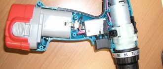
Photo-3. The design of electrical wiring clamp terminals in modern drill buttons
In other words, the prepared wire of a winding or other drill part for installation can easily be inserted into the hole provided for it in the button body, but pulling it back out is problematic - this requires skill and ingenuity. The clamp terminals in the button body itself are installed at an angle of 45 degrees, and made of hardened steel.
If you look carefully at photo 3 presented in this article, you will agree with me that in order to pull out the wire you just need to push out the clip inside the button body and release the mounting cable. To do this, you will need a thin large needle or a thin strong awl, which you need to insert into the hole reserved for mounting the wire and push the clamp inside, thereby freeing the wire from the grip. That’s all, in conclusion I can say that the method I told you works very well (I checked it myself more than once). You can safely get to work and replace the drill button yourself with your own hands. That’s all for today, I’m waiting for your comments below, bye, see you next time!
Electronic screwdriver speed control
The rotation speed of the screwdriver attachment can be adjusted mechanically or automatically. Automatic speed control occurs using a processor. You can set the desired operating parameters using the speed selection toggle switch. It is located on top of the body. In many models, speed control is realized through the start button. The stronger the finger pressure on it, the higher the speed will be.
After reading this article, you received information on how to assemble a screwdriver speed controller with your own hands, became familiar with the design of the force regulator, and understood the function of electronic adjustment of the tool. We hope you found the article useful.
Source
Possible faults
If the drill's performance begins to deteriorate, it is worth having it diagnosed. First you need to check the drive for various damages. Also, first of all, the presence of voltage in the network from which the device is powered is checked.
Battery models can be diagnosed using a special device - a tester. The voltage specified by the manufacturer must correspond to the value given by the testing device.
If the voltage is lower, the battery should be replaced. The most common drill malfunctions:
- problems arising when the button mechanism malfunctions;
- engine breakdown;
- brush wear.
If you know how to connect the tool button, you can easily deal with damage associated with this part. It should also be remembered that many problems that arise when operating a drill are associated with dustiness of the device. It should be cleaned after each use. Otherwise, the tool will last much less.
Electrical faults
The principle of operation of the regulator is based on changing the moment of the switching-on phase of the circuit closure triac relative to the transition of the mains voltage through zero of the beginning of the positive or negative half-wave of the supply voltage.
Therefore, by simultaneously pressing the button, all terminals are tested. Despite the fact that this process is quite complicated, you can do all the work yourself, following some important rules. At the same time, calculating power is a fairly simple task.
The stator is changed as follows: First, carefully disassemble the device body; Remove the wires and all internal parts; After finding out the causes of the breakdown, we replace the spare part with a new one and close the housing again.
This device may have a diagram showing which wires are connected internally. If the battery is working normally, the power supply is normal, look for hardware problems.
Diagnosis of failure
This simple-looking device, during use, gives signals to the user that he will soon need repairs, but not everyone understands them. If the drill begins to work with temporary interruptions, or the button requires pressing harder than before, then these are the first symptoms of incorrect operation of this part.
When you use a cordless drill, the first thing you need to do is measure the battery voltage with a tester - if it is less than the nominal value, then it needs to be charged.
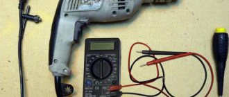
In this case, we are especially interested in the condition and functionality of the product’s on/off button. Let's look at the procedure for checking a key using a classic impact drill as an example. To remove the casing, you will need a Phillips and flathead screwdriver, and for direct diagnostics, a standard tester (multimeter).
Be sure to unplug the power cord from the outlet before disassembling the instrument.
Removing the button:
- Unscrew the bolts on the drill body.
- Loosen the screws holding the network cable.
- Disconnect the reverse.
- Carefully remove the starting block.
How to select spare parts for replacement
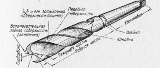
Electric drill structure: 1 - stator, 2 - stator winding, second winding under the rotor, 3 - rotor, 4 - rotor commutator plates, 5 - brush holder with brush, 6 - reverse, 7 - speed controller.
It shows the existing electric motor speed controller with a rotor reverse control and reverse. This unit becomes clogged with dust during work.
If the light comes on, everything is fine with the button, but if you notice a malfunction, it’s time to replace the button. The stator is made of electrical steel with high magnetic permeability. There are many cases when the parameters of the buttons match, but when installed in the drill case they simply do not fit.
When replacing a button, it should be taken into account that the circuit may have a fairly simple structure, or it may be made in reverse. When these components wear out, the reduction gearbox pair experiences increased loads.
This means that you should take care to clean the device after each use - this is the only way to reduce the risk of malfunctions due to contamination of the tool. Drills are different in type, but in terms of power, by the way, when buying a new drill button, you need to take into account the power of the tool, otherwise the button will not last long.
This article will help eliminate this gap. WEIGHT without power supply cable, socket and additional accessories.
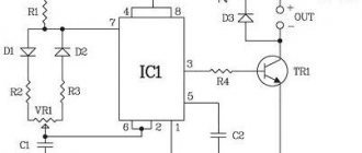
Schematic Electrical Diagram of a Screwdriver
Now you have to use a soldering iron and unsolder the two elements from each other, as shown in the figure. Screwdriver design: 1 - speed controller with reverse, 2 - electric motor, 3 - gearbox.
Resistor Rx sets the highest current.
The graph shows how the temperature of the element temperature, the voltage at its terminals voltage and the relative pressure relative pressure change during charging. It can monitor battery parameters and, if necessary, reduce the current automatically. WE MAKE A SIMPLE BATTERY CHARGER with auto shutdown when fully charged
The electrical signal is supplied directly to the engine rotor through the commutator. Next, you need to carefully assemble the screwdriver button, install it in place and test it. When the breakdown occurred, I was on business in Orenburg and therefore contacted the service center for repairs there.
Replaceable battery.
The rather miniature size of this tool assembly is achieved using microfilm technology.
We visually inspect the condition of the button for dirt and damage. repairing a screwdriver, replacing the power button with your own hands
How to connect the drill button yourself?
For the procedure you will need a flat and Phillips screwdriver, as well as an awl. In the absence of the latter, a bag needle or any other thick needle will do. If the model is small in size, then for greater convenience you can also take tweezers.
Button replacement:
- Loosen a couple of screws holding the network cable.
- We insert the awl into the stator next to the wire and carefully remove the core.
- We pull out the second cable in the same way.
- If the button is not on the clips, then unscrew the screws and take it out.
- We put the new key in place and connect the wires using an awl.
- We install the block on the drill, not forgetting about reverse.
- Carefully lay the wires and press them with screws.
- Close the casing.
Interskol drill power button
In a good half of cases, the wires coming from the stator differ in color. If they are the same, then they will need to be marked so as not to be confused when connecting.
Drill button diagram
Picture 1. Reverse button connection diagram
Drill button connection diagram
The drill button shown in photo -1 is equipped with a built-in electric motor speed controller as well as a built-in rotor rotation direction controller - reverse.
Screwdriver speed controller
An electric screwdriver operates either from a 220 V network or from a rechargeable battery. Its power depends on the battery voltage. The screwdriver rotation speed starts at 15,000 rpm. In addition, a powered screwdriver has 2 rotation speeds: a slower one for screwing, a higher one for drilling. The speed control is located inside the power button. The rather miniature size of this tool assembly is achieved using microfilm technology. Its main part is a triac. The operating principle of the regulator is as follows:
- When the button is turned on, an alternating current having a sinusoidal phase is supplied to the control electrode of the triac.
- The triac opens and current begins to pass through the load.
The response time of the triac depends on the amplitude of the control voltage. The greater the amplitude, the earlier the triac is triggered. The amplitude value is set using a variable resistor connected to the start button. The button connection diagram differs in different models. It is possible to connect a capacitor to the speed controller.