Features of installation work
The pipe is used for laying underground at a depth of no more than 15 m. The minimum laying depth should not be less than 1 m.
When backfilling a trench, fine-grained material should be used, such that the particle size easily fits between the ribs of the corrugation. The size of particles of earth, stones or gravel should not exceed the width between the projections of the corrugated ribs.
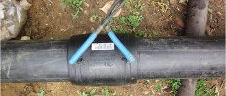
Butt welding connection. A welded connection is made possible due to the large wall thickness of the Korsis pipe and the sufficient width between the stiffeners. The technology for using welding techniques is no different from joining smooth polyethylene pipes.
When using butt welding machines, the parameters of pressure, time and temperature are set, which are set based on the pipe wall thickness.
The welding mode is selected based on the wall thickness. There are pipes that are delivered to the installation site with a welded expansion and connecting socket. For ease of installation, many manufacturers send a batch of products to the site along with spacer rings, couplers and heating elements.
Connection with couplings and O-rings. If the ring is installed in the first grooved groove, then the ring diameter is 120–250 mm; if the connection occurs at the level of the second stiffener, then the circle size is 110–1200 mm.
It is recommended to install the coupling with a constant and evenly distributed force in the longitudinal direction. Do not use impact forces with sledgehammers and jackhammers, which can easily damage O-rings and couplings. Lever devices are used to facilitate installation.
Features of installation of the Korsis pipeline
Korsis corrugated products are suitable for equipping manholes and are lightweight and easy to install. When connecting structural parts of a pipeline, certain requirements are adhered to.
Installation of inspection wells "Korsis"
Inspection wells are divided into types:
- tray - for use in housing and communal networks;
- trayless - for use in road and storm drainage systems;
- inspection;
- differential - provide for a height difference between the incoming and outgoing pipes;
- tangential - large in size with the installation of an observation deck and stairs.
Well shafts are made from pipes:
- "Corsis PRO" with a diameter of 630-1200 mm;
- "Corsis PLUS" with a diameter of 1200-2200 mm.
The well shaft is mounted to the neck using a pipe O-ring, and to the underlying tray using a cuff. An adapter is connected to the neck to exit the well at an angle to the shaft.
Basic requirements for pipeline installation
Installation of Korsis pipes - instructions:
- Installation must be carried out by specialists.
- Do not go beyond the permitted installation temperature range.
- Clean the pipeline connections from dirt.
- To lubricate the planes connected to each other, substances containing oils should not be used: they lead to the destruction of the polymer and reduce the service life of the products.
- Use connecting elements - couplings, O-rings and collars - from the same manufacturer as the pipes themselves.
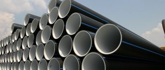
Today, for gravity drainage systems without pressure, there is no need to use heavy steel pipes, since there are Corsys polymer corrugated pipes with increased degrees of rigidity for installation in soils at a depth of up to 15 m. The products are easy to install, have an affordable price and good performance characteristics.
Have you ever had to install sewerage in a country house? Tell us in the comments what polymer pipes you used.
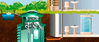
Installation of inspection wells
These independent structural elements are an integral part of the sewer system.
Wells can be made of polyethylene or concrete. Polyethylene structures are divided into two main types. The first type contains a monolithic cast element at the base, which is connected to a vertical section of the pipe. To connect a sewer pipe to it, rubber seals in the form of rings are used, ensuring a waterproof connection.
The second type is different in that it consists of pipe sections welded together. The connection to the main elements occurs using couplings.
If a concrete well is installed, then it is necessary to ensure that the hole in the well corresponds as closely as possible to this indicator of the pipe. All connections are coated with cement mortar.
During the work, a support should be installed for the free end of the polyethylene pipe, which is intended to enter the well wall. First, the work of concreting the well is carried out and only after hardening the pipe is connected.
It is impossible to do two jobs at the same time, as this can cause deformation of the highway under the influence of heavy concrete masses.
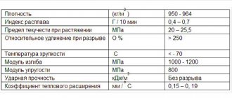
Technical characteristics of polypropylene material
- Polypropylene melts at a temperature of 168ºC.
- Density is 910 per kg.
- The tensile strength is 25–28 MPa.
- The elongation limit at break is more than 200%.
- The material becomes brittle at 20ºC below zero.
- The bending modulus is taken to be 1250–1650 MPa.
- The hardness of the pipe material according to the Rockwell scale is assumed to be 55–75 α.
- Thermal conductivity coefficient is in the range of 0.17–0.23 W per meter.
- The coefficient of specific heat capacity at a temperature of 20ºС is 1.95 kJ per kg.
Abrasion testing is usually carried out using two systems. The first is to determine the amount of material that has been subjected to abrasion and wear after the advancement of abrasive particles. The second indicator indicates the time during which the particles were worn out under the specified conditions.
Abrasion by abrasives occurs due to friction during the rolling of certain abrasive particles, cutting off material components by them, if the flow consists of uneven, sharp and hard elements.
A number of studies conducted by specialists indicate that the mechanism of self-cleaning and deposition of microparticles on the walls of the pipe are directly related to the process of material abrasion.
Sewer underground and above-ground pipeline systems made of polyethylene with a ribbed outer surface are developing and are gradually replacing all other materials for drainage devices. Because of their high performance qualities, they are popular among builders.
Design methods
In matters of designing polyethylene highways, the final decision depends on the final cost of materials, installation and operation together with proper maintenance of complex structures.
The customer, designer, contractor and operational service must work in close tandem and optimize all issues when choosing a route diagram, material, using installation methods and technology, and the mode of use of the finished sewer main.
For work, they use the provisions defined in SNiP for external networks and structures of water supply and sewerage and the standards for the design and installation of sewer and water supply systems.
For gravity sewers, it is recommended to calculate the speed of movement of wastewater in the range from 1 to 4 m per second; for rainwater, a flow of up to 7 m per second is recommended.
Korsis pipe series produced for consumers:
- type PRO is made of polypropylene with a multilayer construction and is produced with rib stiffness SN 16;
- ECO type is made from polyethylene after recycling and recycling;
- the APM type includes products with reinforced mesh in the pipe walls, has a ring stiffness of SN 16, according to the customer’s individual instructions this figure increases to SN 24;
- type PLUS is used in case of requirements to increase the flow diameter of pipes, the internal diameter is from 1200 to 2400 millimeters, rigidity - SN 2, 4, 6, 8;
- type SVT for external sewerage with spiral ribs.
Characteristics of Corsis
Made from low-pressure polyethylene, due to their lower stiffness class, they are used only for laying sewer and storm pipelines. Maximum laying depth:
SN4 – 6 – 6 m; SN8 – 10 m. Characteristics:
Resistance to pressure in the pipe wall: 3.9 Pa at 80° C – 165 h
2.8 Pa at 80° C – 1000 hours.
Resistance to thermal effects at 200° C – 20 min. Density – 950 kg/m³. Mass fraction of carbon – 2 – 2.5. Advantages:
installation at a temperature of −20° C; impact resistance; resistant to chemical and mechanical influences; possibility of bending when laying; durability; simple installation, transportation and storage; low cost.
Corsis pipe diameters.
| Ext. dia.DE in mm | Internal dia. DI in mm | Wall thickness E 4 in mm | Corrugation pitch t in m.m | Width B of corrugation protrusion i | Calc. mass of 1 m in kg. SN 4 | Calc. mass of 1 m in kg. SN 8 |
| 125 | 107 | 1,1 | 12,5 | 6,5 | 1 | 1,2 |
| 160 | 138 | 1,2 | 13,1 | 6,5 | 1,5 | 2,1 |
| 200 | 176 | 1,4 | 16,5 | 8,5 | 1,8 | 2,5 |
| 250 | 216 | 1,7 | 37 | 23 | 2,9 | 3,7 |
| 315 | 271 | 1,9 | 42 | 27 | 4,6 | 5,7 |
| 400 | 343 | 2,3 | 49 | 30 | 7 | 8,7 |
| 500 | 427 | 2,8 | 58 | 38 | 12 | 13,2 |
| 630 | 535 | 3,3 | 75 | 47 | 17,7 | 20,3 |
| 800 | 678 | 4,1 | 89 | 56 | 24,5 | 33,1 |
| 1000 | 851 | 5 | 98 | 60 | 40,5 | 51,7 |
| 1200 | 1030 | 5 | 110 | 80 | 56 | 66,9 |
Description of the Korsis pipe
These products compete quite successfully with reinforced concrete and cast iron pipelines, which are gradually losing their leading positions in the market of plumbing devices and materials.
Polyethylene pipes also have some operational features that must be studied before purchasing and installing a line from a Korsis pipe. To increase strength characteristics, increase reliability and durability, polyethylene is mixed with active additives.
The result is products that have undeniable advantages over reinforced concrete analogues:
- have significantly less weight while maintaining 75% strength indicators;
- do not belong to materials that absorb moisture, therefore they do not respond to freezing and thawing cycles;
- they retain their performance qualities and characteristics throughout their entire service life; even after 40–50 years, quality and ductility indicators remain at the same level;
- the properties of polyethylene make it possible to produce products with resistance to impact and abrasion;
- the material makes it possible to produce products with high levels of ring stiffness;
- due to their low weight they can be easily transported and quickly installed;
- the characteristics of the material make it possible to create and successfully use large-diameter Korsis pipes;
- Compared to metal and reinforced concrete products, they are low cost and permanently resistant to corrosion.
For sewer systems that are installed deep within the earth’s surface, the ability to lie for a very long time without destruction or corrosion is the main indicator of reliability.
Professional builders and private developers confidently pay attention to it
The products are durable, resistant to chemical destroyers and have sufficient strength. The last indicator gains value when a mass of soil presses on the Korsis pipe, laid at great depths. The ribs of the corrugated surface are located in such a way that they accept and redistribute the load, thereby increasing the compressive and bending strength.
Korsis pipes provide all the small details and details, for example, the black wall on the outside resists the effects of ultraviolet rays, and the light inner surface visually facilitates diagnostics during preventive work.
Korsis pipes are produced in two types of geometric shapes with ring stiffness (SN 6, SN 6), which makes it possible to use them at different depths. They produce pipes of the PRO series, which have a rigidity rating of SN 16. Standard sections of products on sale have a length of 12 and 6 meters. At the end of the Korsis pipe, a standard socket with a length of 300 to 1200 mm is welded.
Pipes of all specified strength classes differ only in the thickness of the outer wall, and all overall dimensions are the same. This allows design calculations to be made in the same way for all classes of pipes and to use connecting elements of the same type.
Requirements for the sewer line
The proliferation of double-layer corrugated pipes made of thermoplastics is proceeding at a rapid pace, but it is difficult for non-specialists to select material for laying sewers. To do this, you need to consider the requirements for sewer pipes:
- Long-term ability to maintain hydraulic performance.
- Stability when accepting external loads.
- The ability to maintain sealed properties of suture joints for a long time.
- Resistant to corrosion and destructive chemicals.
- Low ability to accumulate various types of deposits on the internal walls.
- Simplicity and speed of installation and connection.
- Low cost compared to other materials.
The disadvantages of corrugated products include:
- It is difficult to connect pipes using the standard welding method due to the uneven surface.
- It is impossible to repair a damaged place on a pipe by welding an overlay or cutting a hole for a new input.
Laying sewer pipes Korsis
Most often, sewer pipes are laid underground.
Installation requires a laying plan, an excavator and hand tools for backfilling and cleaning the bottom of the trench. The width of the trench is made up to 2.5 m; a sand cushion is made at the bottom, on which the pipes are subsequently laid. They are assembled together using couplings or simple welding. After the final connection and leak testing, the trench and pipe are backfilled with fine pebbles or coarse sand. The height of the protective layer should be such as to completely cover the highway.
If the work is carried out correctly, a warning tape will be laid so that during subsequent excavation the excavator operator can stop in time and not damage the Korsis pipe. After this, the trench is filled with soil and compacted.
- Corrugated polyethylene pipe can be laid at various depths underground.
- Regardless of the rigidity indicator, the pipes are produced with the same dimensional parameters, the outer diameter is 110–120 mm.
- A short-term temperature fluctuation downwards and upwards up to values from -40ºС frost to 65ºС heat is acceptable.
- If the pipeline is used correctly and all operational standards are observed, the service life is determined to be fifty years.
Products
Sewerage » Korsis corrugated pipes » Laying KORSIS pipelines
Construction of a trench
The following trench dimensions are recommended: width - no more than 2-3 pipe diameters, depth between the pipe and the ground surface - at least 1 m. The walls of the trench should be as vertical as possible and reinforced, if necessary, with supports or shields. After filling the pipe, before compacting the backfill soil, the supporting structures must be removed and the bottom of the trench must be leveled. If there are stones and other inclusions in the soil that can damage the rough, the base of the trench must be made of sand or fine gravel so that the ribs of the corrugated outer wall of the pipe do not touch the ground. The use of detrital neo-rolled material is prohibited. When laying pipes in a trench or on supports It is necessary to take all measures to prevent damage to the pipes. When installing pipes, you must make sure that no debris or foreign objects have gotten into them, and that their internal surface is not damaged. It is strictly forbidden to adjust the laying of pipes inside the trench using stones, bricks, etc. Pipes must be provided with stable support , and in those places where pound settlement is possible, it is necessary to use appropriate types of connections or carry out special treatment of the bottom of the trench [10].
categories and general deformation
Let's consider three categories of pipe installation with different types of soil compaction.
Category 1,
Thorough compaction : C f= 1.0
The bottom of the trench is leveled, and stones and other solid objects are removed from the trenches. In the case where the bottom of the trench is hard (for example, in muddy soils), a bedding about 200 mm thick is made from uncompacted sand (if the base soil is sandy, then the use of bedding is not required A pipe is laid on the bottom of the trench prepared in this way, and both sides of the space are filled with Natural soil or sand brought to the construction site. Sprinkling is done in layers to the top of the pipe while simultaneously compacting the sand being filled so that the pipe has good support. Then sand on both sides The pipe is compacted mechanically to a value of at least 9B% according to Proctor. A further layer of about 300 mm thick is poured over the pipe and compacted in the same way. This procedure is repeated until a layer is formed with a thickness of at least 0.7 times the nominal diameter of the pipe. Further filling of the trench is carried out with natural soil.
Category 2.
Moderate compaction : C f = 2.0
This installation category is only applicable when laying in sandy soils. In this case, the pipe is filled with sand to a height of approximately BOV mm above its upper mark, after which it is compacted. Attention should be paid to carefully distributing the sand on both sides of the pipe.
Category 3.
No seal : C f = 3.0
When using this installation category, no special work is required. The bottom of the trench, as well as the compaction of the soil filling the trench, is carried out only with the help of an excavator. Compaction is not carried out layer by layer, and after filling the trench, heavy equipment (for example, an excavator) drives through it. In clayey soils, care must be taken to ensure that large pieces of clay do not damage the pipe,
The applied installation category must take into account the installation conditions of the pipeline. When laying is carried out under a road, then, based on the requirement for the magnitude of soil compaction, installation of category 1 must be used. When the pipeline is laid in an undeveloped area where there is no traffic, installation of category 3 is allowed. For KORSIS pipes with a stiffness class of at least B kPa (5№B) the initial deformation of the pipes immediately after completion of installation work can correspond to the values indicated in Table 16.
Over time (from 3 months to 1.5 years), the pipe continues to deform before the amount of deformation reaches a constant value. The magnitude of this increase in Cf depends on the installation conditions and. in case of installation of category 3, on the type of soil used to cover the pipe (Table 17). The final deformation value is the sum of the indicated values;
(δ/D)end = (δ/D)begin+Сf
where Cf is the time component of the relative deformation, %.
The following maximum values of pipe deformation are allowed (ISO TR 7073):
- for initial deformation - no more than 8%;
- for Cf - no more than 4%;
- for total final deformation - no more than 12.5%.
Table 16. Initial deformation value
| Installation category | Pipe deformation amount | |
| Average | Maximum | |
| 1 | 0,5% | 1 ,0% |
| 2 | 1,0% | 2,5% |
| 3 | 2,5% | 6,0% |
Table 17, Additional deformation value Сf
| Installation category | Soil type | |
| Loose | Dense | |
| 1 | 1 ,0% | 1,0% |
| 2 | 2,0% | 2,0% |
| 3 | 3,0% | 4,0% |
Rice. 22. Permissible pipe deformation after installation
A - ring stiffness, kN/m2; B—initial deformation%; I - thoroughly compacted soil; II - moderately compacted soil; III - no seal
Note: The average strain values immediately after pipe installation are represented by the lower interface of each region, the maximum values by the upper interface. The graphical chart data is valid under the following conditions:
a) laying depth from 0.8 m to 10 m; b) the depth/diameter ratio is at least 2.0. c) developers must establish the permissible, average and maximum deformation values, guided by national requirements, production standards, etc.; d) pipes comply with [2]; e) the quality of the work must guarantee the required degree of soil compaction (installation category), in which the designer must be confident.
As a result of a 25-year study of the dynamics of rough deformation under various conditions, the following patterns were identified, presented in graphical form in Fig. 22.
Recommendations for laying
KORSIS pipes can be welded both in the trench and on the edge. The coupling connection can be installed directly in the trench. Due to the low weight of KORSIS pipes, it is most convenient to connect long straight sections at the edge. However, due to the fact that the collector may be interrupted by shut-off devices or inspection wells, it is not always possible to carry out work outside the trench.
During installation, it is necessary to pay attention to possible thermal expansion, despite the fact that under variable temperature conditions the thermal expansion of KORSIS pipes is significantly (approximately 50%) lower than that of conventional pressure polyethylene pipes.
The connections must provide the necessary hydraulic characteristics and static loads provided for by the design and installed by the manufacturer. When butt welding pipes, the pipe wall thickness e4 provides sufficient resistance to possible stress caused by shrinkage. When couplings are used to connect pipes at air temperatures above 20°C, it is recommended to partially backfill the pipe at small (30-40 m) intervals, and complete it in the coolest part of the day [10].
However, it must be remembered that if the backfill is carried out properly, then the possible longitudinal movement of the KORSIS pipes is compensated by the compacted soil of the backfill. The tightly filled corrugations of the profile “hold” the pipe).
After installation, it is necessary to carry out physical tests of the installed pipe. Hydraulic testing of KORSIS pipes can be carried out by sealing individual sections of the pipe using fixing plugs and applying a test pressure of 0.05 MPa. However, it should be borne in mind that during hydraulic tests, due to the linear expansion of the pipe, the test pressure may decrease slightly, even if the pipe being tested is hermetic. A correctly installed CORSIS pipe with coupling connections can easily withstand the test pressure even for a long time. When installing KORSIS pipes, as well as when installing conventional polyethylene pipes, the requirements [2], [4], [11] must be met.
Pipeline installation in water-saturated soils
The KORSIS pipe, like other polyethylene pipes, floats when immersed in water. It is appropriate to recall that backfill, even if it is dry material, can deform the pipe. Therefore, you must be extremely careful when carrying out this work. Installation in water-saturated soils should be carried out on a dry trench bottom. This ensures the correct construction of the base and slope.
It is necessary to use water reduction systems to remove excess water, which allows pipes to be laid in compliance with the above requirements.
The backfill material must be used to prevent soil movement near the surface of the pipe. The granulometric composition and compaction of the backfill material must be such that the pipe is rigidly fixed and the deformation of the working section of the pipe does not exceed critical.
The particle size of the backfill material should not exceed the width of the corrugation profile. When laying in water-saturated areas, it is recommended to use crushed stone and pebbles of the required size as backfill material.
Acceptance of work
Commissioning of the finished network of KORSMS pipes must take place in accordance with the requirements of the Project and SNiP 3.01.04-37, SNiP III-3-81 “Acceptance into operation of completed construction facilities”, [3] taking into account the “Rules for the execution of work on laying and reconstruction of underground structures."
These rules, published at the beginning of the EO-ies, mainly relate to the construction of sewer networks from traditional materials: ceramic, cast iron, concrete and reinforced concrete pipes. The subject mention of thermoplastic pipes is approximately two years ago. For this reason, a number of provisions of the above-mentioned regulatory documents are not applied during the construction and acceptance of sewerage from plastic pipes or there are no corresponding requirements. During the period of the release of new regulatory documents taking into account the conditions for the construction of sewerage from plastic pipes, acceptance of work must be carried out in accordance with the provisions of these instructions. Tests of gravity sewer pipelines KORSIS must be carried out in accordance with the design and with mandatory consideration of the basic requirements of the above-mentioned regulatory documents and [4]. There are two types of tests for plastic pipelines upon acceptance:
- Test for exfiltration of water from the pipeline (no water leaks from the pipeline);
- Test for water infiltration into the pipeline (no groundwater entering the pipeline).
The exfiltration test is basic and is carried out first. Pipeline tightness tests are carried out between inspection wells by closing the channel using temporary mechanical valves - plugs or pneumatic plugs, filling the channel with water and measuring the pressure drop.
Before carrying out leak tests, the pipe must be sprinkled and partially backfilled. Coupling connections of pipes and connections to wells remain free and not backfilled.
All openings of the pipeline under test, together with the connecting channels, must be hermetically sealed during the test period and protected from water pressure by a stop. When using tees and bends on the route, as well as long connecting channels, coupling connections must be temporarily protected from disconnection during pressure tests.
During testing, the groundwater level must be reduced to at least 0.5 m below the bottom of the trench. Plugs for the period of testing of the pipeline section under study must be equipped with fittings with valves to allow:
- water supply,
- drainage of water from the canal after testing,
- removing air,
- connecting a measuring device.
Water for the sewer pipeline to be tested must be supplied from an open reservoir using gravity. Under no circumstances should the supply duct be directly connected to a duct supplying water under pressure. The canal is filled slowly from the well at the bottom of the canal. After filling the pipeline with water and obtaining a water level in the upper well 0.5 m above the upper edge of the supply hole, it is necessary to stop the water supply and leave the completely filled section of the pipeline for 1 hour in order to remove air and stabilize the water level in the wells. Air is removed from the channel through the highest point. The filling time of a pipeline section should not be less than 1 hour for smooth filling and removal of air from the pipeline.
KORSIS pipes are tested to a pressure of 5.0 m water column. The test pressure may be lower if this results from the deepening of the pipeline, as well as intermediate wells along the channel route. The test time should be:
- 30 minutes for a channel section up to 50 m,
- 60 minutes for a canal section longer than 50 m.
There must be no drops of water on the coupling connections. The pipeline is considered tight when the additional amount of water into the pipeline during testing (minimum 15 minutes) does not exceed 0.02 l/sq.m of the internal wetted surface of the pipe.
According to [11], the permissible volume of water added to the pipeline (water inflow) per 10 m of the length of the tested pipeline during a test of 30 minutes for KORSIS pipes with a coupling type connection on a rubber cuff should be determined by the formula
q = 0.06 + 0.01 D (6.5.1)
Where:
D is the outer diameter of the pipeline, dm;
q is the permissible volume of added water, l.
Storm sewer pipelines are also subject to preliminary and acceptance testing for tightness in accordance with the requirements of this subsection, if provided for by the project.
If the connection is not sealed, it must be replaced and the test repeated. After checking the connections for leaks, they are covered with sand using appropriate tamping.
Infiltration tests are carried out if the groundwater level is higher than the bottom of the pipeline. Rubber sealing rings used when installing KORS1/1S pipes using a coupling have a two-way, equivalent effect. A pipeline leak test to a pressure of 5.0 m of water column protects the pipeline from infiltration of ground water by the same amount. If necessary, tests can be carried out. Infiltration tests are carried out on a completely completed pipeline in a certain area of the sewer network without dividing it into segments, as before, which is associated with the cessation of drainage of the trench. The permissible amount of water during infiltration must correspond to [3, 11].