Currently, when laying underground and above-ground pipelines, not only fixed supports are used, but also sliding ones. This solution allows you to hold the pipeline in the desired position, eliminating the possibility of obstacles due to natural displacement. The main objective of the design is to accept weight loads that are created by the overall system during operation, as well as to protect the thermal insulation coating from damage during installation and further use.
The sliding support option for pipelines has become very popular in areas where there is a need to compensate for seasonal temperature changes. In addition, it ensures maximum stability and immobility of pipes, compensating for longitudinal movements during all kinds of deformations caused by unpredictable temperatures.
Operating principle
It is no secret that a pipeline system can place a large load on spans and supporting engineering structures. This impact is explained by the large weight of fittings, connecting fittings, pipes and other elements that are an integral part of heat supply systems, as well as main and technological transportation lines.
In most cases , pipes are made of metal, which is necessary to ensure maximum structural reliability . However, the use of such material significantly increases its size. And if the pipe contains technological products that use a liquid coolant (if we are talking about heating mains), the weight of a linear meter of pipe increases rapidly. The load becomes maximum when pumping liquid substances, including drinking water and hot water supply, water with antifreeze of heating mains, process solutions, suspensions.
In addition to statistical loads, the operation of the system is accompanied by thermal changes in the linear dimensions and diameters of the component . This is due to seasonal temperature fluctuations and climatic factors. Also, the transported product itself, which fills all the internal spaces, has a special influence on the pipeline. To understand, hot steam can lengthen one linear meter of the steam pipeline by 1.2 millimeters, resulting in a longitudinal displacement of some sections of the system.
The pipes are also affected by torques, transverse and axial loads when pumping a liquid substance. Transportation is complicated by gusts of wind, water hammer, vibrations and other unpleasant incidents.
What are pipeline supports needed for?
To ensure maximum reliability and safety for the pipeline system, not only high-quality components are used, but also reliable support in the designed position. Such a product perceives and correctly distributes the acting loads on the ground or any other base.
An important advantage of the supports is the protection of pipes from bending and disconnection of connecting elements at joints . The structures are equipped with elastic gaskets that are sandwiched between the pipeline and the support.
Sliding devices are characterized by one unique feature: their base is not fixed to the concrete surface, but moves freely along a horizontal plane . To support the pipes, embankments, trenches, racks and shelves are used, on which there are special support shoes. Sometimes the pipeline is also attached to the walls using brackets.
When laying heating mains, a support pad is mounted under the base of the pipes in the tray before routing the heating plants. The solution protects the structure from abrasion and deformation when temperature changes and other climatic factors occur.
Design and its varieties
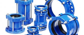
The pipeline support includes several separate parts. Among them:
- base made of channel or corner;
- fastening of holders;
- paronite gaskets;
- semicircular holders;
- special skating rinks;
- connecting nuts, bolts and washers.
These days, the following types of supports are widespread:
- roller;
- clamp
Representatives of the first group ensure efficient sliding of pipes along the guide elements due to the roller. Such structures will be indispensable when connecting pipes in tunnels, where there is a need to support the pipeline along the axis. Movement is limited using special stops. Single-roller and double-roller sliding bearings are available in the market.
As for clamp models, they are capable of providing high system stability to unexpected loads. The hangers used in the design are necessary for efficient movement of pipes.
As SNiP standards state, the supports of a pipeline system can be movable or fixed. As for mobile species, they are represented by:
- sliding clamps - necessary for moving pipes in a specific direction;
- dielectric - characterized by the presence of dielectric gaskets made of paronite, providing the system with reliable protection from the possible effects of static electricity;
- roller - move along their own axis when thermal deformation occurs;
- ball - capable of performing axial and transverse displacement of pipes;
- clamps with a bracket - designed to move pipes in a specific direction.
When choosing the appropriate option for your purposes, pay attention not only to the design characteristics of a particular model, but also to the calculation results obtained by certain general measurements.
Types of structures
For obvious reasons, different products with different characteristics are used for gas and oil pipelines, for technical systems and for supplying hot water or compressed air. Therefore, the first requirement that supporting structures must satisfy is the suitability of the material. This doesn't always mean a perfect match, but it does mean it's fit for purpose: hold, vibration damping, temperature resistance, and so on.
There are 2 main types of structures: movable and fixed.
Movable - or sliding, are used to absorb vertical loads. In addition, they help to evenly distribute thermal deformation. This type of structure allows you to change the position of the pipeline relative to the support. For calculations, it is not so much the purpose - the transmission of gas or compressed air - that matters, but rather the total weight of the pipe with its contents.
There are several types of models:
- roller – rollers are built into the structure, which ensures linear mobility of the steel pipeline;
- clamp - or welded. It is a pendant with which communications are fixed to the ceiling;
- spring - equipped with a spring shock-absorbing block. Can be combined with a clamp;
- support ring is a version of a sliding system in which mobility is ensured by the material of the structure. This is a frameless support, which is made of polymer, that is, it has a high coefficient of thermal expansion.
Fixed - unlike movable ones, they completely eliminate linear or angular displacements. Sometimes they are structurally very similar to sliding ones - clamp ones, for example, but thanks to rigid fixation they guarantee the immobility of the pipeline.
There are the following options for fixed supports:
- body welded - structures are connected to pipes by welding. The device may be different, but with the pipeline, in fact, they form a single whole;
- body clamps - fixed to pipes using flat or round clamps;
- yoke - a type of clamp: the models are equipped with additional stiffening ribs, which improves their performance;
- steeply curved - special structures designed for fixing pipes at bend areas;
- vertical fastenings - are strong paws welded to a vertical surface;
- panel - similar in design to vertical ones, but are used when communications pass through walls.
Different arrangements of supporting structures require different distances between them. However, the latter is determined not only by the type of product, but also by the characteristics of the pipes. For calculations, all these factors must be taken into account.
Features of sliding type supports
In most cases, thermal shrinkage does not affect the operation of the piping system. Sliding elements provide a quick solution to many shrinkage problems. They can support the pipe, leaving only vertical loads. Thus, partial fixation protects the system from unexpected stress when temperature changes. True, for fixed structures, even a small voltage can be fatal and lead to damage.
Despite the contradiction presented above, sliding structures are fixed directly to the pipe, where they slide along its base. In this case, the intensity of abrasion of the pipe during transportation is reduced. There are a number of factors that can lead to permanent or minor shifts. We are talking about:
- changes in pressure inside the system;
- systematic temperature shrinkage;
- vibrations.
If the support is not attached securely enough, dust and dirt, which have characteristic abrasive properties, will begin to appear in the gap formed. Over time, they begin to thin the pipe wall, creating a stress riser. Ultimately, she simply can’t stand it.
Currently, sliding supports for pipelines are sold as a complete set, which includes all related elements. Therefore, you can independently choose the appropriate solution for a specific installation height and pipe diameter. It is better to entrust the installation of the structure to a qualified specialist, since it is problematic to take into account many subtleties on your own without skills and experience. A professional employee will take into account all non-obvious aspects and minimize the likelihood of accidents, reducing the cost of system maintenance.
Advantages
The popularity of sliding supports is due to many advantages and design features. Among them:
- no installation difficulties;
- long service life, regardless of operating conditions;
- reliable and durable design that can withstand maximum loads;
- the presence of various standard sizes, which expands the possibilities for finding a suitable solution for a specific case.
The support is one of the most indispensable components of any heating system. Its absence significantly reduces the life of the pipeline and increases the risk of all kinds of damage under the influence of certain factors.
When choosing the appropriate solution for an individual case, do not forget that a good design maintains the basic position of the pipe on the support sheet as accurately as possible, preventing the aggressive influence of wind or seismic shocks. It also guarantees support for pipes of any weight and diameter with minimal wall stress. As a result, there is no chance of dents or damage. Sliding type supports have high load-bearing capacity at relatively low resource costs.
The market offers a large range of standardized designs, which expand the possibilities of choice and allow you to find any modification that is ideal for your conditions.
When choosing the type of support structure, experts pay attention to both the calculated indicators of the expected forces and the process of interaction between the components. In most cases, designers give preference to support shoes with an anti-friction coating (fluoroplastic), which rest on a support pad (a concrete slab can be used as it). This solution has a positive effect on the sliding of the conventional steel-concrete combination, providing a friction coefficient of 0.5. It makes sense to use roller or ball type supports with a friction coefficient of 0.1.
A high-quality sliding structure can protect main pipelines from unexpected damage and loads, compensating for thermal expansion, vertical and lateral loads, as well as smoothing torque and leveling other physical impacts. As a result, the client is provided with colossal financial savings on repair work, and the likelihood of any unpleasant “surprises” is reduced.
Given these characteristics, sliding supports are an indispensable part of any modern pipeline. The cost of products varies and ranges from several hundred rubles to tens of thousands. It all depends on weight, length, dimensions, design and operational properties, as well as some other aspects.
As for the areas of application, they are indeed very extensive and are constantly expanding. Most often, sliding support is used in:
- metallurgy;
- mechanical engineering;
- oil refining industry;
- construction;
- thermal power engineering;
- housing and communal services;
- gas production
Distances between pipeline supports according to the SNIP table
A correctly selected distance between the support fasteners is one of the operating conditions for the system. The supports allow you to distribute the load, minimize stress, and in certain cases - when arranging heating mains, for example, distribute the temperature load.
SNiP standards include requirements for the distance between supports for pipelines with different diameters, wall thicknesses and purposes. Such data is entered into special tables, which greatly facilitates calculations. It is worth remembering that the table does not contain recommended data, but an exact indication, corresponding to SNiP, how many and what structures are needed.
The table of distances between pipeline supports given in the article concerns sliding structures for steel pipes.
| Outer diameter, mm | Wall thickness, mm | Maximum distance between supports, m | Accepted distance for above-ground and underground installation, m | Accepted distance for underground installation in impassable channels, m |
| 25 | 2,5 | 2.5 | 1,9 | 1,9 |
| 32 | 2,5 | 3,2 | 2,7 | 2,7 |
| 40 | 2,5 | 3,9 | 3,0 | 3,0 |
| 57 | 2,5 | 4,9 | 3,8 | 3,8 |
| 76 | 3,0 | 6,4 | 4,9 | 3,8 |
| 89 | 3,0 | 6,9 | 5,3 | 4,1 |
| 108 | 3,5 | 8,3 | 6,4 | 4,9 |
| 133 | 4,0 | 9,6 | 7,4 | 5,6 |
| 159 | 4,0 | 10,4 | 8,0 | 6,1 |
| 219 | 4,0 | 12,8 | 9,8 | 6,4 |
| 273 | 4,5 | 14,7 | 11,3 | 7,9 |
| 325 | 5,0 | 16,6 | 12,8 | 8,3 |
| 377 | 5,5 | 18,3 | 14,1 | 9,2 |
| 426 | 6,0 | 19,8 | 15,2 | 9,9 |
| 530 | 7,0 | 22,7 | 17,5 | 11,4 |
| 630 | 8,0 | 25,6 | 19,7 | 12,8 |
| 720 | 8,5 | 27,7 | 21,3 | 13,9 |
| 820 | 9,5 | 30,3 | 23,3 | 15,2 |
| 920 | 10,0 | 31,9 | 24,5 | 16,0 |
| 1020 | 11,0 | 33,6 | 25,8 | 16,8 |
The distances between the supports of steel pipelines with equal wall sizes are determined by the diameter. The characteristics of the soil during underground installation also influence. In addition, when installing thermal routes in accordance with SNiP, the distance is affected by temperature deformation. For heating mains, only movable supports are used in order to create an installation offset to compensate for thermal expansion.
Installation features
In order to correctly calculate the optimal distance between future supports, you need to take into account a number of features, including the purpose of the pipeline. To understand, hot water pipes must be equipped with a large number of supporting structures at a short distance from each other. As for cold liquid supply systems, the principle operates in the opposite way.
The installation of such elements on pipelines begins before the pipes begin to be pulled into the cases. Pay attention to maintaining the integrity of the system's factory insulation.
A seamless waterproofing material is fixed between the supports and metal cases, and graphite lubricant is applied to their surface, under the conditions that the pipes will be subject to friction. At the last stage, the clamps are fixed and a high-quality screed is performed. If during installation some parts of the supports are damaged, they should be painted.
The installation of such sliding elements begins simultaneously with the laying of the linear part and without the use of special equipment. Electric arc welding is used for fastening. At different stages of installation work, technical safety measures should be taken into account.
Thus, the sliding support is an essential element that is indispensable in the construction and further use of pipeline systems. In order to draw up the correct project for a future structure, it is better to consult in advance with highly professional specialists, since a low-skilled engineer cannot always accurately calculate the basic characteristics and features of the upcoming work.
Types and differences
If we consider the classification of supports by design, we can distinguish the following types of products:
- Spring fastenings of pipelines. Necessary to absorb loads on the structure. Often combined with other types of designs. Supports and clamp pendants can be adjusted in height and are used for fixation to ceiling beams.
- Products for fastening vertical pipelines and panel supports are usually attached to ceilings or to metal beams. Panel products are necessary to pass the main line through the wall over a short distance.
- Elements of steeply curved bends are used where there is a bend in pipes. In this case, one type is designed for bent bends, the second - for welded ones.
- Clamp sliding body mounts can have a round or flat clamp. The first ones are used for fixing steel products, the others - for steel and polyurethane foam pipes.
- Welded fixed body products. They are quite simply made of steel, are inexpensive, and you can get different fixed structures: from a box to complex elements made for specific needs. Fixation occurs by welding over a certain distance.
- Frameless supports are essentially clamps. In the case of rigid fastening, these are stationary clamp supports; in case of loose attachment to the pipe, these are sliding (movable) supports.
It should be noted that all types, due to their combination with each other, can represent movable and fixed fastenings for pipelines.
Fixed
Fixed-type products allow you to maintain pipeline shifts in the transverse or longitudinal direction. It is the fixed supports that will allow for the most reliable fastening, preventing the pipeline from moving.
They are used in the formation of both underground and above-ground systems.
For channelless underground installation, products with a polyethylene (or polyurethane foam) shell are used for high-quality waterproofing. Above ground systems involve the use of galvanized steel waterproofing.
The fixed support includes the following elements:
- steel pipe;
- hot rolled steel sheet;
- thermal tape and galvanized shell;
- polyurethane foam (PPU);
- centralizer and polyethylene shell.
For such products, only strong steel is used - the calculation is regulated by the table from GOST for pipeline supports 14911-82. There are three types of steel sheets:
- standard quality;
- low alloy;
- high-quality construction.
In this case, the quality of finishing can be normal or increased.
Centralizers are a device that simplifies the centering of pipe ends during installation. There are two types: external and internal. External ones, accordingly, perform alignment from the outside.
They are:
- with hydraulic jack;
- eccentric;
- link
To manufacture the latter type, frost-resistant steel is needed. The design consists of interconnected links that, thanks to a thrust screw, center pipes with a diameter of 57 mm to 2.224 m.
Eccentric centralizers can be used for products of any diameter. With a hydraulic jack, they are used to center deformed or heavy pipes.
Internal centralizers have to be moved using lifting equipment because they are massive. However, their advantage is the use of welding from the inside, which makes it possible to achieve high quality seams.
Fixed supports are used in northern regions where large temperature fluctuations occur.
Sliding
Sliding (movable) support for pipelines is widely used in the above-ground method of laying pipelines. The main task of the design is to ensure permissible movement of pipes along the vertical and horizontal axes, and clamp supports protect the pipeline from abrasion.
Such movable supports are used in cases where the calculation involves frequent and large temperature changes, which means that the material contracts and expands.
Such suspensions ensure the stability and immobility of the entire system and compensate for changes caused by deformations. The design of the fixed support is as follows:
- base - channel or corner;
- metal holders;
- nuts;
- gaskets;
- bolts.
GOST OST 24.125.156-01 for sliding supports of pipelines regulates the parameters of the components.
The following movable types can be distinguished among structures of this type:
- constant effort;
- elastic;
- hard.
There are hard ones:
- sliding fastenings;
- hard suspensions;
- mounting guides.
The former do not allow the pipe to move vertically downwards. If the calculation uses rigid suspensions, the system will be the most mobile. Mounting guides limit horizontal movement in a certain direction or downward.
The greater the load on the elastic support, the higher the displacement of the pipe will be. Constant force sliding fasteners are able to withstand permanent loads.
As a rule, the movable support is pre-painted with primer-enamel or simply primer in several layers. Sometimes a zinc or powder (PPU) coating is applied.
Carbon steel is often used for the manufacture of such elements; low-alloy steel is used for low-temperature applications.
We can distinguish the following types of sliding supports, making calculations on their design:
- ball;
- roller;
- on brackets;
- dielectric;
- sliding clamp support for pipelines.
Roller supports reduce friction between the base and the surface of the pipeline during its movement. Dielectric elements are used for low carbon or carbon steel pipes. The insulation is made from polyurethane foam or a mixture of powder particles, asbestos and rubber.
Ball bearings are used if non-standard fastening is expected, for example, in thermal power plants. The support ring for pipelines allows the pipes to move along the transverse and longitudinal axis.
Products are characterized by durability, which, of course, is determined by the material of manufacture.
The distance between the movable pipeline fasteners must be provided for when designing the system. The calculation is carried out individually: it depends on the material, diameter, length of the pipes, properties of the coating (PUF) of the supports, parameters of the transported medium, and the required height of the line.
Using supports (video)
About design and calculation
All work on arranging supports for pipes must be carried out in accordance with the requirements of the project. Otherwise, actions can lead to an emergency situation. The distances between the supports of steel pipelines should not exceed the calculated data.
The elements must be installed tightly to the pipeline, so the spacing of pipeline fastenings should be minimal. A table of distances between pipeline supports can be used to obtain data.
These data are calculated based on the obtained parameters for strength, deflection, and depend on the diameter of the pipes, the characteristics of the coolant and the method of laying the pipeline.
Supports for fastening pipelines are installed at the bottom of the channels, but without obstructing the flow of water. Sometimes foundations are built for pipeline supports, so their calculation is also necessary.
Reinforced concrete pipeline supports require preparation of the base for installation. Fixed products are often installed near shut-off valves and near PPU pipeline branches.
Calculation of pipeline support is a necessary measure when designing a line. The procedure is performed using external forces and moments. The latter are determined when calculating the pipeline to compensate for thermal changes, taking into account the friction force, internal pressure and force from compensators.
In addition, loads caused by the weight of the structure, transported substances, dust, ice, and so on should be taken into account. You also need to take into account dynamic and wind loads.
Since in each case the calculation will be individual, we give as an example some average figures (for steel pipes):
- for pipe DN 15, uninsulated/insulated - 2.5/1.5 m;
- DN 25, uninsulated/insulated - 3.5/2 m;
- DN 50 - 5/3 m;
- DN 100 - 6/4.5 m;
- DN 150 - 8/6 m.
The above figures are maximum.
Permissible loads are determined taking into account a temperature of twenty degrees. Other cases involve the use of a special coefficient.
As for the cost, the price of pipeline supports with polyurethane foam coating starts at 100-200 rubles (for a guide structure).
The price of a sliding support for pipelines is from 300 rubles.
The cost of installing pipeline supports with polyurethane foam coating is from 500 rubles for 1 structure (also relevant for small-diameter lines and taking into account the fact that it is not necessary to perform work at high altitudes).
Modern science cannot yet calculate real pipelines based on strength calculations. Therefore, when using the most modern software systems, you have to deal not with the actual design of the pipeline, but with its computer model - the design diagram. An inexperienced designer usually sees his task as reproducing as accurately as possible a drawing of a real pipeline on a computer screen. At the same time, it is overlooked that there is a big difference between the pipeline drawing and its design diagram. The design scheme is a pipeline design freed from features that are not significant from the point of view of strength assessment. For the same design, several design schemes can be selected, depending on which aspect of the pipeline operation interests the designer. The use of a calculation scheme is necessary, since a full account of all the properties of a real structure is impossible.
For example, the resistance of soil to pipeline movements along and across its axis is modeled by elastic bonds, the rigidity of which depends on the magnitude and direction of movement of the fixed point on the pipeline axis, soil properties, laying depth and a number of other factors. Moreover, these dependencies are nonlinear and are determined on the basis of experimental studies. The properties of sand are the most studied today. This apparently explains the requirements for ductless installation of heating networks in a trench - the underlying layer and backfill must be made with compacted sand. In other soil environments, the results may not be reliable.
In the Start
a continuous soil environment is modeled (and this is another schematization of reality) by elastic supports placed at a fairly close distance from each other, , . If the section is located in a horizontal or almost horizontal plane (the angle of inclination to the horizon is no more than 10°-12°), then a support with three connections is placed (Fig. 14a), and the connection along the pipe axis simulates the friction force. If the section has an inclination angle from 12° to 90°, then the friction force along the pipe axis can be neglected, and the soil can be modeled with two elastic bonds that prevent movement across the pipe axis (Fig. 14b). The connections may not be applied at all if the length of the inclined section is small compared to the length of the pipeline, since its influence on the distribution of forces will be negligible. As we can see, the computer model is a certain approximation to reality, which takes into account only the most significant factors affecting the distribution of forces in the pipeline.
To correctly select a design scheme, you need some experience. Below are some typical examples.
Example 1: Figure 15 shows a ductless pipeline that runs partially in a duct. If there are no lateral (transverse to the axis of the route) movements at points A and B, then the design scheme will correspond to that shown in Fig. 15b – there are sliding supports along the entire length of the section in the channel. If lateral movements at the entrance and exit of the channel can occur and a limiter is installed to prevent them (for example, a round hole with a sleeve), then two options are possible:
When the design of the limiter does not prevent the rotation of pipeline sections in the horizontal plane (short sleeve), we have a design diagram shown in Fig. 15c – two guide supports at points A and B. The operating diagram of the guide support, which ensures freedom of movement along the pipe axis, is shown in Fig. 15v;
When the design of the limiter prevents such rotation (for example, the length of the sleeve is greater than the diameter of the pipeline), instead of guide supports, non-standard fasteners with a two-way rigid angular connection in the horizontal plane are installed (Fig. 15d). Finally, if the AB section is located on a long straight route and has a relatively short extent, it can be ignored altogether, considering it in the same way as underground sections outside the boundaries of the canal.
Example 2. When reconstructing a heating network, part of a pipeline with polyurethane foam insulation runs in an old channel, which is covered with sand (Fig. 16a). In the absence of lateral movements at the inlet and outlet of the channel, the entire pipeline can be calculated as pinched in the ground (Fig. 16b). The difference will only be in the calculated depth: to the left and right of segment AB it will be equal to h
1
(from the surface of the earth to the axis of the pipe)
,
and between points A and B –
h 2
(from the axis of the pipe to the bottom of the channel floor slab), since the weight of the soil above the channel slab is not transferred to the pipe.
The described model is correct in relation to solving the problem of strength assessment. If the stability of the AB section is checked - the possibility of loss of the rectilinear form of equilibrium as a result of axial compression, then it is necessary to additionally take into account not only the weight of the soil lying above the channel, but also the weight of the channel floor slabs.
Example 3. The pipeline is laid in a casing under the road. Since all loads from transport, overlying soil, etc., are absorbed by the case, and stresses from the weight of the pipeline laid in the case cannot lead to its destruction due to almost continuous support, section AB can be considered weightless (Fig. 17a) .
At the inlet-outlet, it is enough to apply horizontal friction forces P
tr
collected from half the length
L.
Such a scheme, although different from the real one, takes into account the most significant features of elastic work and provides a certain margin of safety in relation to sections of the pipeline pinched in the ground. If diaphragms are placed at the ends of the case to prevent lateral movements from adjacent underground sections, then this is modeled by guide supports (Fig. 17b). Other options for a computer model for this case can be the calculation schemes shown in Figures 15b and 15c. True, such a complication, in our opinion, will not be compensated by the accuracy of the obtained calculation results.
Example 4. Insertion into an existing AG channelless pipeline (Fig. 18), which was installed with pre-stretching (starting compensator at point B). A common mistake made by designers in this case is a joint calculation of the old and new sections of the heat pipeline with the inclusion of a starting compensator in the calculation model. This is true only if the stretching of the AG section using preheating is carried out again.
Rice. 18. Scheme of insertion into an existing pipeline
If the branch is inserted without re-laying the existing route, then point B will remain motionless and the pipeline from point A to point D will be constantly in a tense (stretched) state. mm , using preheating
(deformation of the starting compensator at the moment of its closure). Tension uniform along the entire length can be modeled by displacements of fixed supports at points A and D, and these displacements should be equal in magnitude
,
mm
and are directed in opposite directions along the axis of the AG section (shown in the figure by red arrows).
Thus, the use of any software system for calculating the strength of pipelines does not relieve specialists of the need to think a lot and seriously about how to correctly perceive a real structure and how to choose a computer model for it to evaluate the strength.
When installing sanitary installations, it is necessary to ensure: a) tight connections between pipes, with fittings and appliances; b) strength of fastenings of system elements; c) straightness of laying and absence of kinks in pipeline sections; d) proper operation of fittings, equipment, safety devices and instrumentation; e) the ability to remove air and drain water from systems; f) compliance with the design slopes of pipelines; g) reliable fastening of drive guards at pumps and fans. Pipes must be checked for blockages before installation; The ends that are temporarily left open should be closed with inventory plugs. Dismountable connections on pipelines are made at the points where they are connected to the fittings and where this is necessary according to local conditions. All dismountable pipeline connections, as well as fittings, inspections and cleaning must be in places accessible for maintenance. Demountable connections are not allowed to be located in the thickness of walls, partitions, ceilings and other building structures. In places where dismountable joints, fittings, inspections and cleanings are located during hidden installation of pipelines, it is necessary to install access hatches. On risers and branches, the distance from the main line to the fittings on them is taken to be no more than 120 mm. The deviation from vertical pipelines should not exceed 2 mm per 1 m of pipeline height. When laid in furrows or shafts, pipelines should not be adjacent closely to the surface of the building’s construction parts. Pipelines, heating devices and air heaters at coolant temperatures above 105° C must be separated from combustible building structures at a distance of at least 100 mm, or these structures must have fireproof thermal insulation. Fastening pipelines to wooden plugs is not allowed. Connections (joints) of pipelines are not allowed to be placed on supports. The designs of hangers, fastenings and movable supports must allow free movement of pipelines when the temperature of the coolant and the environment changes. The distance between supports for steel pipelines in horizontal sections is taken in accordance with the data in Table. 177, if there are no special instructions in the project.
Table 177. DISTANCE BETWEEN SUPPORTS OF STEEL PIPELINES
In residential and public buildings, risers made of steel pipes are laid at a floor height of up to 3 m without fastenings, and with a floor height of more than 3 m - with the installation of fastenings at half the height of the floor. In industrial buildings, risers are fixed every 3 m. Fastenings for horizontal cast iron sewer pipes are installed every 2 m, and for risers - one fastening per floor, but no more than 3 m between fastenings. The fastenings of cast iron pipes are located under the sockets. Steel pipelines with a coolant having a temperature of 40-105 ° C, where they intersect ceilings, walls and partitions, must be enclosed in sleeves for free movement of the pipes during temperature changes. When the coolant temperature is above 105 ° C, pipelines passing through combustible or difficult-to-burn structures are enclosed in sleeves made of non-combustible material. The gap between the sleeve and the pipe must be at least 15 mm when filled with asbestos and at least 100 mm without filling. The sleeves should protrude 20-30 mm above the finished floor level. The edges of the sleeves must be flush with the surfaces of walls, partitions and ceilings. On the risers of single-pipe heating systems with displaced closing sections, sleeves are not installed in the ceilings. In this case, the distance from the riser to the heating device in flow-through (without closing sections) heating systems or to a displaced closing section must be at least 180 mm. Places where pipelines pass through firewalls should be sealed with non-combustible material (asbestos). Cold water pipelines where they pass through wooden building structures must be wrapped with roofing felt. Sanitary and heating appliances are installed plumb and level. Same type sanitary and heating appliances and fittings located within the same room must be installed uniformly and at the same height. When placing hot water tanks on wooden structures, gaskets made of asbestos cardboard 5 mm thick should be installed in places where metal comes into contact with wood. Sanitary cabins are installed on a leveled base. Before installing the cabins, check that the top of the sewer riser of the underlying cabin and the prepared base are in the same plane. The axes of sewer risers of adjacent floors must coincide. The ventilation ducts of the cabins must be connected before laying the floor slabs for this floor. External inspection, as well as hydraulic testing of pipelines with hidden installation are carried out before they are closed, and insulated pipelines - before applying insulation. Heating systems and water supply systems must be thoroughly flushed with water before commissioning. In winter, internal water supply systems and heating systems are connected to external networks immediately before starting up the systems.
The pipeline is not always laid underground. Sometimes, especially when it comes to large highways, this option turns out to be unprofitable. And in order to hold the pipeline in a given design position or even move the system if necessary, special supports are used, located at a precisely calculated distance from each other.