Important notes.
Displacement of the initial contour when cutting teeth is used to restore worn surfaces of wheel teeth, reduce the depth of penetration on gear shafts, to increase the load capacity of a gear transmission, to perform transmission with a given center distance not equal to the pitch distance, to eliminate undercutting of the legs of gear teeth and tooth heads wheels with internal teeth.
Displacement of the generating circuit in practice is usually used in the manufacture of spur gears and very rarely helical gears.
This is due to the fact that in terms of bending strength, an oblique tooth is stronger than a straight one, and the required interaxial distance can be ensured by an appropriate angle of inclination of the teeth. If height correction is rarely used for helical gears, then angular correction is almost never used.
Helical gears operate smoother and quieter than straight gears. As already mentioned, oblique teeth have higher bending strength and a given interaxial distance can be ensured by the angle of inclination of the teeth and without resorting to displacement of the generating circuit. However, in gears with oblique teeth, additional axial loads appear on the shaft bearings, and the wheel diameters are larger than spur gears with the same number of teeth and module. Helical wheels are less technologically advanced to manufacture, especially wheels with internal teeth.
Subscribe
to article announcements in the windows located at the end of each article or at the top of each page.
Link to download the file: modul-zubchatogo-kolesa (xls 41.0KB).
How is the precision of gear manufacturing indicated?
When manufacturing, any of their types have a number of errors, among which there are four main ones:
- kinematic error, mainly associated with the radial runout of the gear rims;
- error in smooth operation caused by deviations in the pitch and profile of the teeth;
- the contact error of the teeth in the gear, which characterizes the completeness of contact of their surfaces in engagement;
- lateral gap between the non-working surfaces of the teeth.
To control the first three errors, the standards establish special indicators - degrees of accuracy from 1 to 12, and manufacturing accuracy increases with decreasing indicator. To control the fourth manufacturing error, there are two indicators:
- type of gear coupling - indicated by the letters A, B, C, D, E, H;
- side clearance tolerance - indicated by the letters x, y, z, a, b, c, d, e, h.
For both indicators of lateral clearance, the designations are given in descending order of its magnitude and tolerance.
Conventionally, the accuracy of gears is indicated in two ways. If the degree of accuracy for the first three errors is the same, then one common numerical indicator of the degree of accuracy is set for them, followed by letters indicating the type of mating and the tolerance for lateral clearance. For example:
8-Ac GOST 1643 – 81.
If the accuracies for the first three errors are different, then three numerical indicators are put in the designation sequentially. For example:
5-4-3-Ca GOST 1643 – 81.
Circle diameters
Consideration of the geometry of gear pairs is impossible without determining the diameters. Several of them stand out on each detail. A widely used diameter is the diameter of the circle along the ridges, sometimes called the diameter of the vertices. It determines the maximum dimensions of the wheel rim. Its opposite is the diameter of the circle of the depressions. The difference between these values, divided in half, gives the total length of the tooth. But this parameter is not used in its pure form. When making calculations, it is customary to highlight the height of the head and stem of the tooth. The boundary separating these two concepts is called the pitch circle of the gear. The diameter of this circle serves as a reference parameter when performing geometry calculations, since it is by it that the circumferential pitch and engagement modulus are determined. Another diametrical parameter, called the basic circle, describes the theoretical curve, which is the basis for constructing the involute. The diameter of the base circle is used to construct a specific tooth profile.
Ticket No. 31
1. Basic parameters of gearing.
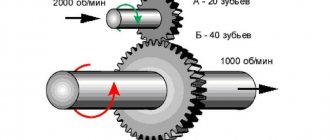
A single-stage gear train consists of two gears—driver and driven. The smaller number of teeth in a pair of wheels is called a gear.
and the larger one
is a wheel.
. When designating the parameters of the gear (drive wheel), odd indices are assigned (1, 3, 5, etc.), and the parameters of the driven wheel are assigned even indices (2, 4, 6, etc.). The main elements of a gear wheel are teeth, each tooth consists of a tooth head and a stem: The teeth are located on the rim of the wheel and together with the rim they form a gear ring: the thinner part of the wheel - the disk connects the hub to the rim; inside the hub a hole is made for the shaft with a groove for the key .
Gearing is characterized by the following main parameters:
Normal step Pn Pn = π ⋅ m
d a
— diameter of the teeth tips; da = m ⋅ (Z + 2)
d r
— diameter of the tooth cavities; df = m ⋅ ( Z − 2.5)
d a
—
initial diameter;
d
— pitch diameter; d = Z ⋅m
p t
— circumferential step;
h
— tooth height; h = 2.25 ⋅ m
h a
is
the height of the tooth stem; ha = 1.25 ⋅ m
With
— radial clearance; C = 0.25 ⋅ m
b
— crown width (tooth length); bb = (6 ÷ ⋅ m
e t
is
the circumferential width of the tooth cavity;
s t
— circumferential thickness of the tooth;
— center distance;
A
— pitch distance between axes;
Z
- number of teeth.
Pitch circle
- the circle along which the tool is rolled when cutting. The pitch circle is connected to the wheel and divides the tooth into a head and a stem.
The tooth module m is the part of the pitch circle diameter
per tooth.
Modulus is the main characteristic of tooth sizes. For a pair of meshing wheels, the module must be the same.
A linear value, one time smaller than the circumferential pitch of the teeth, is called
the circumferential module of the teeth and is denoted m:
The dimensions of cylindrical spur gears are calculated by the circumferential module, which is called the design module of the gear, or simply the module;
denoted by the letter t.
The module is measured in millimeters. Modules are standardized
Definitions of other gearing parameters are given below.
Initial circle -
each of the intertwining circles of the transmission gears belonging to the initial surface of a given gear.
The initial circles
are conjugate, i.e.
this concept refers to a pair of wheels in mesh (to gear). When the interaxial distance changes, the initial diameters also change accordingly, since they are equal to the sum of the radii of these circles. Thus, a pair of wheels in mesh can have any number of initial circles, while for a single gear wheel the concept of an initial circle is generally meaningless.
By pitch diameter d
the circumferential steps correspond to the standard module
t.
For spur gears,
Main
are called the circles along which the involutes unfold, outlining the profiles of the teeth.
Circles of protrusions and depressions
are called circles that bound the peaks and valleys of the teeth.
Line of engagement
is called the geometric location of the contact points of the teeth in the mesh. In involute gearing, the engagement line is straight, normal to the profile of the teeth in the engagement pole and tangent to the main circles.
Engagement angle
called the angle between the line of engagement and the perpendicular to the line of centers.
Spiral angle
of the teeth of helical gears is the angle between the axis of the tooth and the generatrix of the pitch cylinder or cone.
To determine the main parameters of the gear transmission, the pitch radius is taken. If the center distance in the gear is equal to the sum of the pitch radii, then the initial and pitch circles in this case coincide. In the following we will consider just such a special case of linking.
Tooth height
h
is the radial distance between the circles of the tops and bottoms of the gear:
Tooth head
— its part located between the pitch circle of the cylindrical gear and the circle of the tops of the teeth;
h
is the height of the tooth head. hf = m
Tooth stem
- part of the tooth located between the pitch circle and the circle of the cavities (height of the tooth stem
h f ).
Radial clearance
- the distance between the surfaces of the tops of the teeth and the cavities of the gear and wheel:
The circumferential thickness of the tooth
s t is
the distance between opposite tooth profiles along the arc of the concentric circle of the gear wheel.
Ring width
b
is the greatest distance between the ends of the teeth of a cylindrical gear along a line parallel to its axis.
Center distance -
the distance between the axes of the transmission gears. aw = (Z wheels + Z gears)m/2
Basic linking theorem
can be formulated as follows:
the general normal to the profiles of the teeth at the point of their contact intersects the center line at point P, called the engagement pole and dividing the center distance into segments, inversely proportional to the angular velocities.
Consequence: to ensure a constant gear ratio, the position of the P
on the line of centers must be constant.
2. List of potentially dangerous and harmful production factors using the example of a workshop for machining parts. Regulatory legal documents establishing maximum permissible values for parameters of hazard sources.
Hazardous production factor
(OPF) is a production factor, the impact of which on a worker under certain conditions leads to injury or another sudden sharp deterioration in health. Trauma is damage to body tissues and disruption of its functions by external influence. An injury is the result of an industrial accident, which is understood as a case of exposure to a hazardous production factor on a worker while performing his job duties or tasks of a work manager.
Harmful production factor
(VPF) is a production factor whose impact on a worker under certain conditions leads to illness or decreased ability to work.
Diseases arising under the influence of harmful production factors are called occupational.
Hazardous production factors include, for example:
• electric current of a certain strength;
• hot bodies;
• the possibility of the worker himself or various parts and objects falling from a height;
• equipment operating under pressure above atmospheric, etc. Harmful production factors include:
• unfavorable meteorological conditions;
• dust and gas contamination of the air;
• exposure to noise, infra- and ultrasound, vibration;
• the presence of electromagnetic fields, laser and ionizing radiation, etc.
All hazardous and harmful production factors in accordance with GOST 12.0.003-74 are divided into physical, chemical, biological and psychophysiological.
To physical
factors include electric current, kinetic energy of moving machines and equipment or their parts, increased pressure of vapors or gases in vessels, unacceptable levels of noise, vibration, infra- and ultrasound, insufficient illumination, electromagnetic fields, ionizing radiation, etc.
Chemical
factors are substances harmful to the human body in various conditions.
Biological
factors are the effects of various microorganisms, as well as plants and animals.
Psychophysiological
factors are physical and emotional overload, mental overstrain, monotony of work.
Existing safety standards are divided into two large groups: maximum permissible concentrations
(MPC), characterizing the safe content of harmful substances of a chemical and biological nature in the air of the working area, as well as
maximum permissible levels
(MPL) of exposure to various hazardous and harmful production factors of a physical nature (noise, vibration, ultra- and infrasound, electromagnetic fields, ionizing radiation etc.).
Psychophysiological hazardous and harmful production factors are specifically regulated. They can be characterized by the parameters of labor (work) loads and (or) indicators of the impact of these loads on humans.
The classification of harmful substances by degree of danger includes four classes. Extremely hazardous substances, MPC < 0.1 mg/m3 (for example, lead, mercury have MPC = 0.01 mg/m3). Highly hazardous substances, MPC = 0.1-1.0 mg/m3. Moderately hazardous, MPC = 1.0-10 mg/m3. Low hazardous, MPC > 10 mg/m3.
Based on the nature of development and duration of the course, two main forms of occupational poisoning are distinguished - acute and chronic.
Chemical substances, based on the nature of their effects, are divided into general toxic, irritating, synsibilizing, mutagenic, carcinogenic, and affecting reproductive function.
Initial data and measurements
In practice, engineers are often faced with the task of determining the modulus of a real-life gear in order to repair or replace it. At the same time, it also happens that design documentation for this part, as well as for the entire mechanism into which it is included, cannot be found.
The simplest method is the running-in method. Take a gear for which the characteristics are known. Insert it into the teeth of the part being tested and try to roll it around. If the pair engages, then their step coincides. If not, continue the selection. For a helical cutter, choose a cutter suitable for the pitch.
This rule of thumb works well for small gears.
For large ones, weighing tens or even hundreds of kilograms, this method is physically impossible.
Calculation results
Larger ones will require measurements and calculations.
As is known, the module is equal to the diameter of the circle of the protrusions divided by the number of teeth plus two:
m=De/(z+2)
The sequence of actions is as follows:
- measure the diameter with a caliper;
- count the teeth;
- divide the diameter by z+2;
- Round the result to the nearest whole number.
Wheel tooth and its parameters
This method is suitable for both straight and helical gears.
Calculation of the parameters of the wheel and gear of a helical gear.
Let's move on to the example with a helical gear and repeat all the steps that we did in the previous section.
It is practically very difficult to measure the angle of inclination of the teeth with the required accuracy using a protractor or protractor. I usually rolled the wheel and gear on a sheet of paper and then made preliminary measurements using the protractor prints of the dividing head of the drawing board with an accuracy of a degree or more... In the example presented below, I measured: β a 1 = 19 ° and
β a 2 = 17.5 °.
Once again, I draw your attention to the fact that the angles of inclination of the teeth on the cylinder of the vertices
β a 1 and β a 2 are not the angle β involved in all basic transmission calculations!!! Angle β is the angle of inclination of the teeth on the pitch diameter cylinder (for transmission without offset).
Due to the small values of the calculated displacement coefficients, it is appropriate to assume that the transmission was performed without displacement of the producing contours of the pinion and gear wheel.
Let's use the Excel service “Parameter Selection”. I once wrote about this service in detail and with pictures here.
In the main menu of Excel, select “Tools” - “Select parameter” and fill in the window that appears:
Set in cell: $ D $33
Meaning: 0
Changing cell value: $ D $22
And click OK.
We get the result β =17.1462 °,
x Σ( d ) =0, x 1 =0.003≈0, x 2 =-0.003≈0!
The transmission was most likely made without displacement, the module of the gear wheel and pinion, as well as the angle of inclination of the teeth, we have determined, we can make drawings!
Main settings
To ensure mobility and operability, the design of individual parts of the mechanical transmission must be consistent in size and geometry. For this purpose, when describing such devices, it is customary to use a system of special parameters. These include geometric, weight, size and strength values, fixed by standards. The use of standard parameters makes it relatively easy to calculate standardized gears and ensures guaranteed interfacing of all products with each other. Naturally, for different types, the parameters will be slightly different. The following discusses the terms associated with the design of an involute cylindrical wheel. These parameters, for the most part, describe the main characteristics of other wheel options.
The tooth section of most gears is based on an involute profile, which is obtained on the basis of the curve of the same name. Its use is easily standardized, characterized by high manufacturability and low requirements for the assembly quality of the mechanism. The main parameters of an involute gear are the engagement module and the number of gear teeth. With the same outer diameter of the parts, the values of these quantities can differ significantly in different design options.
The number of teeth determines the gear ratio and the geometric dimensions of the teeth. On the drive wheel of the gearbox it is smaller than on the driven wheel. As a result, one normal revolution of the drive gear leads to the rotation of the driven wheel only at a certain angle. The ratio of the number of teeth of two wheels gives the value of the gear ratio. The size of the teeth is determined as the ratio of their number to the circumference of the wheel. In order to simplify calculations and guarantee engagement between different wheels, an additional parameter is provided, called the engagement module. Any gears with the same module ensure interaction with each other and can be used to build mechanisms, without additional processing.
The sum of the tooth width and root width together gives the pitch of the gear. Taking into account the unevenness of the profile along the radius and the dependence of the arc length on the diameter, an infinite number of values of this parameter can be determined in each wheel. For the purpose of standardization, it is customary to consider a step along a pitch circle, also called a circular step. The ratio of this step to pi gives the engagement modulus. In some cases, angular pitch, measured in degrees, is used to describe gears. The standards also provide for several other angular values. For example, to simplify equipment setup when making wheels, the angular width of the tooth and the angular width of the cavity are considered. They are also determined on the basis of the dividing circle.
Advantages and disadvantages
A feature of the worm gear is the presence of braking torque and a large range of gear ratios and torque. Positive characteristics include:
- gear ratio within 8–100;
- works quietly;
- rotation starts and stops smoothly;
- high precision of movements;
- possibility of displacement by a small amount;
- compactness of the unit;
- self-braking transmission.
Transmission of motion in a pair of worm and worm wheel is possible only in one direction. When the driven part tries to rotate, a braking torque occurs. This is used in swing drives and lifting mechanisms.
The main disadvantage is the power loss associated with high friction. This leads to rapid wear of parts, especially the wheels. Disadvantages include:
- low efficiency;
- friction;
- high heat;
- making a crown from expensive materials;
- frequent eating;
- rapid wear;
- constant adjustment of engagement by tightening the worm;
- complex manufacturing.
Worm gearing requires high precision in the manufacture of screw gearing and cleanliness of processing. The transmission does not tolerate dust and other debris entering the work area. Requires intensive lubrication and cooling.
What is the difference between a sprocket and a gear?
The biggest difference between a sprocket and a gear is how each operates on a functional level. Both tend to be the grooved wheels used on cars, and their basic appearance is often very similar indeed - but how they work and what exactly they do tends to be really different. In general, a gear is a gear designed to engage other gears and transmit motion to them, which in turn can cause motion elsewhere. A sprocket, on the other hand, is a gear designed to engage and directly move a flexible, dented or perforated object, such as a chain or belt. Each application differs as a result. Sprockets are most common when they contain a moving belt or chain, as is common in bicycles, conveyor belts, and film projection reels. Gear drives are generally preferred in all other scenarios, including automobiles and heavy equipment. Not only are the mechanisms more universally useful, but they also don't need to be repaired or retooled as often.
Calculation of worm gear ratio
The driving part that transmits rotation, the worm, has no teeth. Threads are cut on it with the number of starts: 1, 2, 4. Worms with 3 turns are not provided for by GOST. They can be considered and calculated only theoretically. When calculating the gear ratio, instead of the number of gear teeth, the number of thread starts is taken.
Calculate the gear ratio of the worm gear, the formula is similar to other gears:
where U is the gear ratio; Z1 – number of passes on the worm; Z2 – number of teeth on the wheel.
Reverse transmission of torque from the wheel to the worm shaft is impossible. Due to strong tooth friction and low transmission efficiency, the wheel cannot be a drive wheel. This allows you to avoid using brakes in lifting mechanisms. It is enough to regulate the rotation of the worm shaft.
Gear ratio calculation
The gear ratio of a worm gear is calculated by the ratio of the sliding speed of the worm and the shaft.
Where V1 is the sliding speed of the worm; V2 is the sliding speed of the worm wheel. Similar to w1 and w2 angular velocities; dδ1, dδ2 – diameters.
By substituting the formulas for the values of sliding speeds and mathematical abbreviations, the formula for the gear ratio of the worm gear is obtained:
Where i is the gear ratio. In a worm gear it is equal to the gear ratio.
The characteristics of worm gears are standardized according to GOST 2144-76. For a worm with 1 and 2 starts, the gear ratio can be 8-80. For 4-way worms the range of values is smaller, in the range of 30-80.
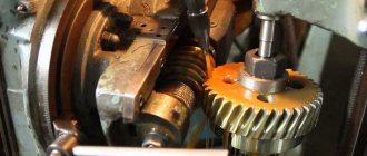
Gear shafts
The disadvantage of the combined design is that the shaft must be made from the same material as the gear, often higher quality and more expensive than required. In addition, when replacing a gear, for example, due to wear or breakage of the teeth, the shaft must also be replaced. Despite this, in gearboxes the gear is often made integral with the shaft and even with a thickness significantly exceeding the specified standards. This is due to the greater rigidity and strength, as well as the manufacturability of the gear shaft, which ultimately justifies its cost.
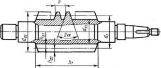
Rice. 1. Conditions for cutting teeth on the gear shaft
In some cases, the ring gear goes deeper into the shaft body. When deepening a tooth into the shaft body, the entry and exit areas of the cutter should be taken into account (Table 1). The possibility of the cutter coming out should also be taken into account when cutting adjacent crowns on the gear shaft (Fig. 1; a, b).
Table 1. Length of track a, mm, for cutter exit (Fig. 1)
| m, mm, cutters | 2 | 3 | 4 | 5 | ≥ 6 |
| a/m | 15 | 14 | 13 | 12 | 10 |
Typically, the teeth of the gear shaft are located on a protruding rim. In this case, to allow the cutter to come out, it is recommended to maintain the following ratio of the dimensions of the internal diameter of the gear or worm with the seating diameter for the bearings (Fig. 2):
The remaining structural elements of the gear shaft are determined in the same way as the structural elements of shafts.
Rice. 2. Main dimensions for cutting: gear shaft (a, b); worm (in)
Construction of an involute gear
There are several methods for constructing the involute gearing used to make gears, which can be done manually or using automatic construction systems.
When designing gear engagement, not only geometric parameters are taken into account, but also the manufacturing process, as well as the desired dynamic and strength characteristics of the finished mechanism.
The construction of a gear involute consists of several stages:
- Graphic construction of a circle of radii (determined based on the required number of teeth and strength characteristics of the finished mechanism).
- A straight line is drawn through the engagement pole in the current of contact with the original circles (built at the required engagement angle).
- The circles of the wheels must touch along the resulting straight line. Rolling it around the circumference of the first wheel, the point coinciding with the pole, forms the first involute. The same manipulation with wheel 2 allows us to obtain a second involute.
In the production of gears, teeth are produced using several methods: copying and rolling. If it is necessary to produce a small part, they resort to the forming method, in other words, hot rolling. This method is less accurate, but the shape of the cutter when copying does not allow making miniature cuts.
The copying method involves rotating the cutter along the surface, forming teeth. It cuts one cavity in one pass between adjacent teeth. Then the cutter returns to its base position while simultaneously rotating the workpiece to the required pitch angle. This manufacturing method is quite accurate, but its productivity is low.
A more advanced method is the running-in method. It is based on an enveloping motion corresponding to the desired movement of the gear when engaged. The manufacturing process is similar to the movement of gears at work. This type of engagement is called machine engagement. The working tool in this case is made in the form of a round, toothed cutter or tool rack.
Preparation of drawings
The manufacturing process begins with the immediate preparation of the drawing. In this case, production is significantly simplified, and the accuracy of the resulting product is significantly increased. When developing a drawing, the following information is indicated:
- Bore hole diameter. For gears, corresponding shafts are made, which have a certain mounting diameter. This indicator is standardized and is selected depending on the size of the product and the amount of force applied.
- Key sizes. The key hole can be very different; the dimensions are selected depending on the loads that will be applied. It is worth considering the fact that the sizes of the keys are standardized.
- Module. This parameter is considered the most important, since an erroneous module can reduce the performance of the mechanism.
- The outer and inner diameters that determine the size of the tooth. It is worth considering that this element of the product is characterized by a fairly large number of features.
- The angle of the tooth relative to the axis of rotation. There are gears with straight and oblique teeth.
The production of gears of any size is possible only with the use of special machines that are designed to solve the task.
Technological tasks in the production of the product in question may differ significantly. Important points include the following:
- Dimensional accuracy. The hole that acts as a seat for the shaft has the most accurate dimensions. In most cases, it is manufactured according to the 7th quality if there are no more requirements for the product.
- Form accuracy. In most cases, when manufacturing gears, there are no special requirements for shape accuracy. However, the mounting hole must be located in the central part of the product, since even a slight displacement can lead to the inability to use the product.
- Relative position accuracy. The greatest demands are placed on the way the teeth and other structural elements are positioned relative to each other. If the geometric shape is violated, there is a possibility of a runout effect and other problems during the operation of the product.
- Hardness of the working surface. The main requirements are related to the hardness of the working surface. The gears are constantly in contact, the frictional force can cause rapid wear of the surface. To obtain the required hardness index, heat treatment is carried out. The recommended value is HRC 45...60 with a cementation depth of 1-2 mm. As studies have shown, the hardness of the unhardened surface is HB 180-270.
- Choosing the right material also matters. Depending on the application of the product, they can be made of carbon, alloy steels and plastics, and in some cases cast iron. Alloyed ones, in comparison with carbon ones, are characterized by greater hardenability, as well as a lower tendency to deformation. The material used must be characterized by a homogeneous structure, due to which the strength significantly increases after heat treatment. In the manufacture of high-precision products, alternating mechanical and thermal processing is carried out.
All main parameters are determined at the time of creation of the technological map. Creating a map yourself is quite difficult, since it requires having the appropriate skills and knowledge.
Application of gears
The areas of application of gears are very extensive. Today, similar mechanisms are used in various industries. Studies indicate that several million copies of such products are manufactured per year. Considering the application and purpose, we note the following points:
- A spur gear is used to increase or decrease the transmitted force. Examples of their application include internal combustion engines or gearboxes, drilling and metallurgical rigs, and mining equipment.
- Bevel gears are used much less frequently. This is primarily due to the fact that they are quite complex to produce. Application area: complex mechanical transmission with variable angles and load changes. An example is the drive axles of vehicles, as well as conveyors and other devices used in the agricultural sector.
The scope of application depends on the design features of the mechanism, as well as the type of material used in production.
During operation, a monotonous moderate noise is heard. If extraneous sounds appear, this may indicate significant problems, for example, severe surface wear. Maintenance is carried out as follows:
- A visual inspection is required to eliminate the possibility of cracks or chips on the surface.
- Particular attention is paid to ensuring that the wheels engage correctly during operation. Too much clearance can cause excessive wear and other problems because the load is not distributed evenly. The gap is changed by adjusting the position of the shaft and bearings.
- At the time of work, attention is paid to ensuring that there is no end runout or other uneven movement.
- To determine the correct movement, marks are applied to the teeth using special paint. Until they dry completely, the shafts are turned several times. The shape of the fingerprint determines how correct the connection is.
- After the paint has dried, care is taken to ensure that the point of contact is in the middle of the tooth height. The position can be changed by installing special pads under the bearings.
- At the time of maintenance, the required amount of lubricant is added. As previously noted, without it the degree of surface wear increases significantly.
Periodic maintenance can significantly increase the service life of the device. At the time of inspection of the device, attention is also paid to the condition of the shaft, bearings and other elements that ensure stable and reliable operation. For example, a slight bend of the shaft causes increased wear on a certain part of the wheel. In the most difficult cases, it breaks.
Main parameters of cylindrical gears
The standard applies to cylindrical external gears for gearboxes and accelerators, including combined ones (bevel-cylindrical, cylindrical-worm, etc.), made as independent units. The standard does not apply to gearboxes of special purpose and special design gearboxes. For built-in gearboxes, the standard is recommended
Center distances
| 1 row | 40 | 50 | 63 | 80 | 100 | 125 | — | 160 | — | 200 | — | 250 | — | 315 | — | 400 |
| 2nd row | — | — | — | — | — | — | 140 | — | 180 | — | 225 | — | 280 | — | 355 | — |
| 1 row | — | 500 | — | 630 | — | 800 | — | 1000 | — | 1250 | — | 1600 | — | 2000 | — | 2500 |
| 2nd row | 450 | — | 560 | — | 710 | — | 900 | — | 1120 | — | 1400 | — | 1800 | — | 2240 | — |
1st row should be preferred to 2nd
Nominal gear ratios
| 1 row | 1,0 | — | 1,25 | — | 1,6 | — | 2,0 | — | 2,5 | — | 3,15 | |
| 2nd row | — | 1,12 | — | 1,4 | — | 1,8 | — | 2,24 | — | 2,8 | — | |
| 1 row | — | 4,0 | — | 5,0 | — | 6,3 | — | 8,0 | — | 10 | — | 12,5 |
| 2nd row | 3,55 | — | 4,5 | — | 5,6 | — | 7,1 | — | 9,0 | — | 11,2 | — |
The 1st row should be preferred to the 2nd. The actual values of the gear ratios should not differ from the nominal ones by more than 2.5% when the nominal is less than 4.5 and by 4% when the nominal is more than 4.5
The gear width coefficient (the ratio of the gear width to the center distance) must correspond to: 0.100; 0.125; 0.160; 0.200; 0.315; 0.400; 0.500; 0.630; 0.800; 1.0; 1.25
Numerical values of the width of gears are rounded to the nearest number from the Ra20 series according to GOST 6636
With different widths of mating gears, the value of the gear width coefficient refers to the narrower of them
Safety factor when working a tooth on both sides
for example: reverse gear teeth or pinion teeth in planetary gears
| Wheel material and heat treatment | Steel and cast iron castings without heat treatment | Steel and cast iron castings with heat treatment | Steel forgings, normalized or improved | Forgings and castings of steel with surface hardening (ductile core) | Steel, normalized or tempered, as well as surface-hardened | Volume hardened steel | Steel, subjected to carburization, nitriding, cyanidation, etc. | Cast iron and plastic wheels |
| Coeff. | 1,9 | 1,7 | 1,5 | 2,2 | 1,4 — 1,6 | 1,8 | 1,2 | 1 — 1,2 |
Center distances for two-stage non-aligned general purpose gearboxes
| High-speed stage | 40 | 50 | 63 | 80 | 100 | 125 | 140 | 160 | 180 | 200 | 225 | 250 | 280 | 315 |
| Low speed stage | 63 | 80 | 100 | 125 | 160 | 200 | 225 | 250 | 280 | 315 | 355 | 400 | 450 | 500 |
| High-speed stage | 355 | 400 | 450 | 500 | 560 | 630 | 710 | 800 | 900 | 1000 | 1120 | 1250 | 1400 | 1600 |
| Low speed stage | 560 | 630 | 710 | 800 | 900 | 1000 | 1120 | 1250 | 1400 | 1600 | 1800 | 2000 | 2240 | 2500 |
Center distances for three-stage non-aligned general purpose gearboxes
| High-speed stage | 40 | 50 | 63 | 80 | 100 | 125 | 140 | 160 | 180 | 200 |
| Intermediate stage | 63 | 80 | 100 | 125 | 160 | 200 | 225 | 250 | 280 | 315 |
| Low speed stage | 100 | 125 | 160 | 200 | 250 | 315 | 355 | 400 | 450 | 500 |
| High-speed stage | 225 | 250 | 280 | 315 | 355 | 400 | 450 | 500 | 560 | 630 |
| Intermediate stage | 355 | 400 | 450 | 500 | 560 | 630 | 710 | 800 | 900 | 1000 |
| Low speed stage | 560 | 630 | 710 | 800 | 900 | 1000 | 1120 | 1250 | 1400 | 1600 |
Content
- 1. History
- 2 Spur gears 2.1 Longitudinal tooth line 2.1.1 Spur gears
- 2.1.2 Helical wheels
- 2.1.3 Chevron wheels
- 2.1.4 Wheels with circular teeth
- 7.1 Run-in method 7.1.1 Run-in method using a comb
- 8.1 Tooth trimming
Application
The high properties of gears are reflected in a wide range of applications. Many industrial mechanisms use gearboxes designed to reduce the speed of rotation of the motor shaft for transmission to process equipment. In addition to changing the speed, such a device also increases the mechanical torque. As a result, a low-power engine with a high rotation speed is capable of driving a slow and heavy mechanism.
In order to reduce the size of the gearbox, it is often made multi-stage. A large number of gears engage in sequential engagement with each other, providing a high gear ratio. A classic example of such a device is a conventional mechanical watch. Thanks to a variety of specially selected gears, the speed of movement of the second, minute and hour hands differ from each other by exactly 60 times.
By changing one set to another, you can get different output shaft speeds. This principle of operation formed the basis of gearboxes widely used in the automotive industry, machine tool industry and other industries.
A regular gear can also be used to increase the speed of the output shaft relative to the input. In general, to do this, it is enough to rotate the gearbox or swap the connection points of the motor and the final mechanism. This device is called a multiplier. Among the features of its application, it is necessary to take into account the engine power reserve comparable to the gear ratio of the mechanism.
Gears are also used to change the direction of movement. Two cylindrical gears with the same number of teeth implement the function of changing the direction of rotation of the shaft. Gears of a conical or crown design are used if it is necessary to change the position of the axis in space. The driving and driven gears in such mechanisms are rotated relative to each other at any angle, the value of which can reach 90 degrees. In this case, the gear ratio is often equal to unity, which ensures the same shaft speeds.
In addition to simple gear variants containing gears, several special models have been developed. In order to reduce material consumption, in mechanisms with a limited rotation angle, only part of the gear is used. This sector, having all the basic properties of gearing, is characterized by lower weight and cost.
Another option, called planetary gear, is also characterized by low weight and dimensions. At the same time, the device provides a high gear ratio and a reduced noise level during operation. Structurally, such a transmission consists of several gears with different degrees of freedom. Due to this, the mechanism can not only transmit rotation, but also add or separate the angular velocities of different shafts located on the same axis. Today, a large number of planetary gear options have been developed, differing in the type and relative arrangement of gears. Planetary gears are widely used in automotive and aviation equipment, and heavy metal-cutting equipment. Among the disadvantages that hinder the spread of gears of this type, it should be noted the low efficiency and high design requirements for the precision of manufacturing of individual parts.
Toothed bevel wheels
The design of bevel gears (Fig. 9) differs from the design of cylindrical gears in the relationships in the part of the ring gear.
Rice. 9. Design of bevel gears: a, b, c – turned; c, d – stamped; g, e – cast; e – composite (prefabricated)
Classification
In the direction of the turn, transmissions are mostly right-handed. Sometimes the left direction of the thread is found.
Worm gears are classified according to the shape of the outer surface of the worm:
- cylindrical;
- Globoid.
The concave surface of the drive part increases the number of teeth that are in mesh at the same time. As a result, efficiency and transmission power increase. The disadvantage of globoid worms is that they are difficult to manufacture. The coils must be of the same height with a concave outer surface.
Worms are distinguished by the shape of the thread:
- Archimedean;
- convolute;
- nonlinear.
The Archimedes worm is distinguished by a straight involute in cross-section. The convolute has a convex configuration, close to the shape of a regular gear. Nonlinear profiles have a convex and concave surface.
The gear wheel has an inclined tooth of a reverse configuration, the shape of which coincides with the cavity between the threads.
The location of the worm relative to the wheel can be:
- top;
- lateral;
- lower.
The upper one is optimal for high-speed gears. The side one is the most compact. With the crankcase lubrication method, the oil is in the sump and the lower part, rotating, lubricates the rest; the lower location of the worm is more convenient.
Worm wheels are helical gears. The axes of the parts are usually located at an angle of 90°. In heavily loaded mechanisms, the angle can be 45°.
Gear wheels are divided according to the tooth profile:
- roller;
- concave;
- straight.
By type they can be:
- with continuous rotation – full;
- gear sector.
The sector can be of different sizes, from half a circle to a working length shorter than a worm.
Design
The worm gear gets its name from the driving part that transmits torque. The driven part has a tooth with an oblique cut. Along the rim there is a radial understatement of the surface. This increases the line of contact between the thread and the tooth.
The rotation axes of the parts are located at an angle. Usually it is 90°, but can be 45°. This arrangement of parts is used in heavily loaded low-speed gears, with a point speed on the outer surface of less than 5 m/sec.
When the gear interacts, the thread surface does not push the teeth in the direction of rotation, but slides along the involute, as if pushing it aside. As a result, strong friction and heating of parts at the point of contact occurs.
The worm pair must be well lubricated, cooled and have anti-friction properties. The material of the worm cannot be changed; it is cut from chromium steel and undergoes hardening, grinding of the thread surface or sugaring - processing with a plate with a shallow depth of cut. The tool pushes the surface of the thread rather than cutting it. A hardening is created on the top layer, strengthening the working surface and making it smooth.
Material for the crown
The gear ring is made of a relatively soft material with high abrasion resistance. Tin bronze and brass are mainly used. For low-speed manual transmissions, the crown can be made of gray cast iron. Depending on the rotation speed, the ring gear is made of the following material:
- 5 – 25 m/sec – tin bronzes OF10-1, ONF;
- ≤ 5 m/sec – Br.AZh9-4, aluminum-iron bronze;
- ≤ 2 m/sec – the crown can be made of cast iron.
Bronze is much more expensive than steel and is softer. Parts are made entirely from it, the dimensions of which are within 160 mm. Large parts are machined from steel and only the crown is bronze. It is hot seated on the shaft and secured with pins along the connection line so that the crown does not rotate. After cooling, the wheel is finished and the tooth is cut.
Diameter calculation
The diameter of the wheel is calculated along the centerline of the tooth - the width of the tooth and the cavity are equal. The outer radius used for manufacturing and calculations is determined theoretically. Once the processing is completed, it is located outside the actual wheel rim.
Sliding occurs along the line of the pitch diameter - the middle of the tooth in height. It is calculated by the formula:
where d2 is the pitch diameter of the gear; m – module; z2 – number of wheel teeth.
The outer radius of the tooth has one center with the axis of the worm.
Ring gear width
The width of the worm wheel crown is determined by the number of turns of the screw using the formula:
where b2 is the width of the crown; 0.315 and 0.355 – calculated coefficient; Z1 – number of screw thread starts; a – center-to-center distance; aw is the distance taking into account the displacement of the worm relative to the gear.
The offset distance determines the size of the gap between the working elements of the parts.
Gear (gear):
A gear or gear is a part that, depending on the application, can have a different number of teeth, made in different shapes, located on a cylindrical or conical surface, and which meshes with the teeth of another gear.
Gears or gears , due to the meshing of teeth, perform the following tasks: transmitting rotational motion from one part to another with changing torque, increasing or decreasing speed, as well as converting rotational motion into translational motion using a gear rack.
Technological process
The gear manufacturing process on large production lines is as automated as possible. The classic technical process is characterized by the following features:
- To begin with, the basic parameters of the product are determined, for example, the number of teeth, modulus and degree of accuracy of geometric dimensions.
- The next stage is to carry out the procurement procedure. Most often, stamping is carried out using a horizontal forging machine.
- To improve performance, normalization is performed. Such heat treatment reduces stress inside the material.
- The turning-screw-cutting procedure allows you to obtain a workpiece of the required dimensions. To do this, surface turning and chamfer boring are performed.
- After machining the spur gears, re-normalization is performed.
- The workpiece is subjected to gear hobbing. For this, a semi-automatic 5306K or other similar equipment is used.
- The next step is metalworking. The technological process determines the appearance of burrs and other defects, which are eliminated when using the 5525 semi-automatic machine. On lines with low productivity, cleaning is carried out manually.
- After obtaining the teeth, heat treatment is performed, for which a HDTV installation is often used. Hardening can significantly increase surface hardness and wear resistance.
- Surface grinding. To obtain the surface of the required quality, grinding is performed. There are quite a lot of different equipment that are suitable for sanding a wide variety of surfaces.
- Mounted gears have become widespread. They are mounted on a shaft and can be of large or small sizes. The attachment version is fixed using a key. You can obtain a keyway by using a slotting machine.
- Gear grinding is also carried out using special machines.
https://youtube.com/watch?v=KbjmqvPM-1c
In conclusion, we note that the gear hobbing procedure is quite complex and requires the use of special equipment.
Worm wheel cutting
During design, a model of a worm wheel is created. Using it you can easily determine the cutting method:
- cutter approach from below;
- end
The end one requires a tool that exactly replicates the worm. Gives good accuracy and cleanliness of processing. It is difficult to align the cutter, it is necessary that at the end of processing it has a position relative to the wheel that exactly corresponds to the worm.
Cutting teeth on the crown
The worm wheel has a semicircular recess along its outer diameter. This allows the parts to fit better along the involute and shift the axis, increasing the contact area. The center of the recess radius must coincide with the axis of the worm.
Worm wheel cutters must have the same outside diameter as the worm. Externally, it repeats the shape of the leading part, only instead of a continuous thread line there are rows of cutters. The cutting plate exactly matches the thread in shape, but is wider by the size of the gap. As a result, the configuration of the counter part - the worm wheel - exactly repeats the shape of the thread, the depressions coincide with the protrusions of the threads.
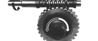
The cutter is aligned in the plane of the worm axis, touching its surface. The ring gear rotates around a vertical mandrel or its own shaft, providing tangential feed of the outer surface relative to the axis of the cutting tool. Worm wheel cutting occurs with the synchronous movement of the tool and the part rotating around their axes. The rotation speed ratio is determined by the gear ratio. With each revolution, the crown moves closer to the rotating cutter.
The cutting tool can be fed from below and from above. But in most cases, radial cutting is used as the most convenient and accurate.
Worm wheels and worms
The gear ring of the worm wheel, according to the operating conditions of the worm pair, must be made of antifriction materials (bronze, brass). Typically, worm wheels are made of components: the disk and wheel hub are made of steel or gray cast iron, and the crown is made of antifriction material.
The following methods of connecting the crown to the disk are used.
Banded wheel design , in which the bronze crown is mounted on a steel or cast iron disk with tension (Fig. 10, a). The design is simple to manufacture and is used for wheels of relatively small diameters, as well as for gear wheels that do not experience thermal loads. When heated to high temperatures due to the higher temperature coefficient of bronze, the fit may weaken due to greater linear expansion of bronze than cast iron.