Cantilever milling machines
Cantilever milling machines (KFS) are designed for processing flat and shaped surfaces of small and medium-sized parts of arbitrary shape: flat, body-type, such as bodies of rotation and figured. In addition to milling, machines can carry out drilling, countersinking, boring and reaming of holes, as well as thread cutting. The main area of use of FSC is single and small-scale production. However, when equipped with special devices and devices for automating work cycles, as well as CNC systems, machines can be effectively used in mass production. The width of the working surface of the table is taken as the main parameter by which the size ranges of machine tools are constructed. To process parts from several sides, machines can be equipped with rotary tables with a horizontal and/or vertical axis of rotation. The dimensions of the FSC (Fig. 4.41) are standardized (GOST 165-81).
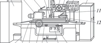
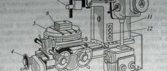
Rice. 4.41. Horizontal cantilever milling machine 6P80G. The main components of the machine: (A) - bed with gearbox and spindle assembly; (B) — trunk with suspension; (B) - table; (D) - additional connection between the console and the robot; (D) - transverse slide; (E) — console with feed box; (G) - base of the machine. Controls : 1 — handle for shifting the gearbox; 2 — handle for switching the spindle; 3 - handwheel for manual longitudinal movement of the table; 4 — handle for turning on the longitudinal feed of the table; 5 - handwheel for manual transverse movement of the table; 6 — handle for manual vertical movement of the console; 7 — handwheel for switching the feed box; 8 — feedbox shift handle; 9 - handle for turning on and reversing the transverse and vertical feed of the table.
The machine is designed for milling various parts of relatively small sizes. Machining of parts is carried out using cylindrical, disk, shaped, angular, modular and face milling cutters, both up and down milling. The machine is used in individual and mass production. If you have a dividing head, you can mill spur gears, racks, grooves, etc. Sufficient drive power and a wide range of speeds and feeds allow you to successfully operate the machine with both high-speed cutters and cutters equipped with carbide inserts. The cutting movement is the rotation of the spindle with the cutter. Feeds are movements of the table with the workpiece in the longitudinal, transverse and vertical directions. Auxiliary movements are quick movements of the table in the same directions. Principle of operation . The workpieces are placed directly on the table, in a vice or special devices. To process parts in several positions, a universal dividing head is widely used, which allows dividing turns of the workpiece into the required number of equal parts. Attachment cutters, cylindrical, disk, etc., are installed on spindle mandrels, tail cutters directly in the spindle or in a collet chuck. When installing cutters on mandrels, one end of the latter is inserted into the spindle cone, and the other into the suspension hole. Face milling heads are fixed to the end of the spindle. The machine is configured in accordance with the configuration and dimensions of the workpiece by moving table B, cross slide D and console E. Design features. The machine has a separated cutting motion drive, i.e. the gearbox is mounted in the frame as a separate unit, and rotation is transmitted to the spindle by V-belts. This ensures vibration-free operation of the machine even at the highest spindle speeds. The spindle is mounted on precision double roller bearings of the 3182100 series of high rigidity. The spindle is relieved from bending forces from the belt drive, since the drive pulley is mounted on independent bearings. To ensure more uniform rotation of the spindle, its drive gear is made massive, so it simultaneously serves as a flywheel. Quick stop of spindle rotation is ensured by the presence of a brake with an electromagnetic drive. The machine has two trunk suspensions: one on roller bearings, designed for high-speed work; the other is on a sliding bearing, ensuring work with cutters with a diameter of less than 75 mm. To increase the rigidity of the system, the trunk B can be connected to the console E by an additional connection G. The feed drive has a ball safety clutch, which eliminates the possibility of breakage of drive elements when the load increases excessively. For down milling, the table longitudinal feed drive has a mechanism for periodically eliminating the gap between the lead screw and the nuts.
Technical characteristics of the machine 6P80G
| Working surface of table (mm) | 200x800 |
| Number of spindle rotation speeds | 12 |
| Spindle rpm limits | 50 — 2240 |
| Number of table feeds | 12 |
| Table feed speed limits (mm/min): | |
| longitudinal | 22,4 -1000 |
| transverse | 16 — 710 |
| vertical | 8 — 355 |
| Table rapid movement speed (mm/min): | |
| longitudinal | 2400 |
| transverse | 1710 |
| vertical | 855 |
| Main motor power (kw) | 2,8 |
Traditionally, wide-universal milling machines (SHUIFS), which are equipped with advanced tooling, are classified as a separate group of cantilever milling machines (Fig. 4.42).
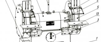
Rice. 4.42. Widely versatile horizontal cantilever milling machine: 1 - rotary head; 2 — inclined head; 3 - transverse support
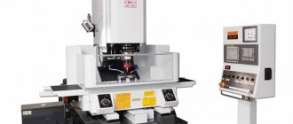
For processing low and flat parts, it is always convenient to use cantilever milling machines with a vertical spindle. The layout of such a machine is shown in Fig. 4.43.
The KFS supporting system consists of cast iron bases and racks. The stand has guides for vertical movement of the machine console.
The tables have an elongated rectangular shape with a length to width ratio of 2.5:1, which makes it possible to work with additional devices, as well as process long parts. To fasten fixtures and workpieces on tables, longitudinally located T-shaped grooves are used.
Spindle units that are stationary or located in a quill (or in a retractable spindle) experience significant loads and are mounted on radial or angular contact
Rice. 4.42. Vertical cantilever milling machine: 1 – stand; 2 – rotating device; 3 – tool clamping mechanism; 4 - spindle head; 5 – slider; 6 – vertical spindle.
roller bearings.
The tool is installed using a cone with a taper of 7:24 or at the end of the spindle with centering along its outer diameter. Torque is transmitted by a parallel key made at the end of the spindle. Manual or mechanical devices are used to clamp the tool in the spindle.
Manually controlled machines use step-controlled wires, which consist of an asynchronous electric motor and a stepped gearbox. The automated version of the main drive uses DC motors, and uses two- or three-stage gearing to provide constant power over most of the spindle speed range.
The feed drives of manually controlled machines use unregulated AC electric motors with stepped feed boxes.
In SHUIFS and vertical KFS with a slider, equipped with CNC, separated drives with an adjustable electric motor are used, which is connected through a gearbox or directly to ball mechanisms for moving the executive bodies.
Table
The main working element of a milling machine, which moves on a slide. On the surface of the table there are clamping and other fixing devices for firmly securing workpieces. For this purpose, the part has longitudinal grooves. The joint operation of the table, console and slide ensures the supply of the workpiece to the cutter. Movement in longitudinal, vertical and transverse directions is possible. Typical equipment usually has manual and mechanical feed. The use of one method or another depends on the tasks:
- For idle runs and installation movements of the table, a manual, mechanical method is used
- For working feed, mechanized feed is most often used.
Additionally, the possibility of rapid movement of the table is provided, the so-called rapid movement in all three directions. The movement is carried out at a constant speed (most of the machines are equipped with an additional clutch or high-speed motor), while the working feeds have a multi-stage shift box. The operator independently selects the mode depending on the material of the workpiece and cutter, as well as the type of processing.
Purpose and scope
The 6P82 cantilever milling machine is designed to work with all types of cutters and perform a wide range of work:
- processing of side surfaces;
- creating protrusions and recesses;
- milling straight and curved grooves.
The model is designed for processing metals of different hardness and viscosity:
- cast iron;
- steels;
- bronze;
- alloys of non-ferrous metals.
Installation of devices increases the number of technological operations. On the machine, from one installation, the upper surface is processed, the ends are milled, holes are drilled and bored.
Important!
When installing a special tool, plexiglass, polyurethane and other dense materials are processed on the 6P82 milling machine.
The main products produced on the 6P82 model are rectangular-shaped parts of varying complexity: plates, gaskets, inserts, pillows and others.
Spindle units
The spindle unit is a standard equipment mechanism that serves to fasten a part (tool) and transmit torque from the gearbox to the cutting tool. The spindle is manufactured with high precision and must have rigidity and strength. It is made from alloy steel, undergoes thermal hardening, grinding, and balancing.
Spindle units perform two types of movement: rotational and translational. Some machines can use both types of motion at the same time. For example, a milling machine both rotates the part during the cutting process and feeds. For a certain category of units, the simultaneous use of both types is provided.
All spindle units of metal-cutting machines have a similar design.
Requirements for spindle units:
- ensuring a given rotation speed;
- reliable fastening of workpieces or tools;
- the required speed of movement to the tailstock of the machine;
- maintaining high dynamic qualities;
- maintaining a constant temperature regime and not being subject to thermal deformation;
- minimal energy losses;
- constancy of dynamic characteristics.
Performance criteria:
- accuracy (characterized by radial, axial and axial runout of the spindle and for average machines is 5-8 microns. Bearings are selected approximately three times more accurately than the permissible runout. The most accurate machines have a runout of 0.1-0.02 microns),
- speed (cutting speed of workpieces made of steel and cast iron reaches 1600-2500 m/min, aluminum - 3000 - 4000 m/min, and plastics - 3000 - 10000 m/min),
- load capacity,
- static stiffness,
- dynamic characteristics,
- energy losses,
- heating of supports,
- static, dynamic and temperature displacements of the front end of the spindle,
- work resource.
Based on their bearings and motor, we can draw conclusions about the pros and cons of any spindle. They determine the scope of application - high speeds and easy cutting. For example, a small engine forces you to sacrifice torque to achieve higher speeds, and small bearings have less rigidity. Therefore, a constant compromise is required between cutting speed and cutting forces.
For the manufacture of spindle catches, tool alloy steels are used. The most commonly used: St45, St40X, 20X.
When choosing machines, you need to pay attention to their operating parameters:
Reliability.
This refers to the ability of the equipment to perform its basic functions over a certain period of time.
Durability
Durability - characterizes the service life of the machine until the first major repair or its write-off.
Maintainability
Maintainability is the ability of equipment to eliminate breakdowns through maintenance or repair.
All these and other parameters ensure the manufacturability of the machine design, which determines the optimal costs for production, repair and maintenance during operation.