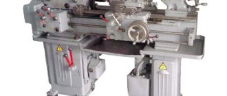
6M82 is a worthy product of the domestic machine tool industry. The key advantage of the 6M82 milling machine is versatility. It can perform a wide range of milling jobs. The table rotates around an axis, thanks to which the unit is capable of producing spiral products.
The machine is configured for several automatic and semi-automatic modes. Therefore, it is used not only in private work, but also on flows in serial industrial operations. The unit is capable of milling parts made of hard alloys.
Information about the manufacturer of the 6M82 cantilever milling machine
6M82 was developed and produced at the Gorky Milling Machine Plant. The opening date of the plant itself is 1931.
The 6H series of milling equipment, published in 1951, already won the main prize at the Brussels international exhibition in 1956.
In 1960, the manufacturer launched a new 6M series, and in its series was the 6M82 machine.
6M differs from the previous series in that the manufacturer has increased the following technical parameters:
- spindle speed,
- speed of table movements and feeds.
In addition, the handwheel has been moved to the front of the unit, making it easier to manually adjust the position of the table.
Later, the company developed such series as 6P, 6T-1 and 6T. The Gorky plant is still one of the leading enterprises in the Russian machine tool industry today.
Purpose and scope
The task of this model is to mill parts of different configurations, working universally. This “M” series machine effectively processes cast iron, low and high alloy steel, and non-ferrous metals. It is used to mill toothed circles, screw holes, frames, and narrow holes.
If you need water meters in Astana, we advise you to contact professionals who have been on the market for several years.
Whether it is external or internal processing, flat or shaped surface, this machine copes with the task flawlessly.
Increased technical capabilities and rigidity make it possible to use the potential of all kinds of carbide cutters and fast cutting tools.
This powerful unit, among other things, is automated. Thanks to the use of automation, the machine successfully copes with small- and large-scale production of parts without the involvement of highly qualified personnel.
Basic indicators
Dimensions of the working plane – 320 x 1250 mm. The maximum distance from the spindle axis to the working surface is 30 - 410. The maximum distance between the end of the spindle and the supporting bearing is 700 mm.
Electric motor power – 7 kW. The rotation speed of the main engine is 1440 rpm, the horizontal spindle is 31.5 ... 1600.
The operating accuracy of the unit is equal to class N.
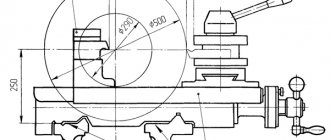
Table Rotation Options
The working surface can be moved:
- Longitudinal (700mm manually and with mechanics),
- Transversely (260mm by hand and 240mm mechanically),
- Vertically (by 380 mm using both methods).
The maximum rotation angle is set to +/-45 degrees.
Dimensions
The length of the machine 6M82 is 2260mm, width – 1745mm, and height – 1660mm.
The total weight of the installation is 2800 kg.
Limits of machine use in terms of power and power loads
The main limitations for devices with high and medium rotation speeds are related to the maximum speed of the cutting tool and the power of the engine that provides movement.
High cutting speed requires the use of high-speed operating modes. Thus, increased machine productivity and vibration resistance are achieved.
When a cylindrical high-speed cutting tool is used, feed intensification up to 1500kg is allowed.
Heavy Duty Limits
Heavy duty milling, first of all, requires high strength and stability of the cutter. Experts recommend adhering to the following conditions in such work (Table):
| Index | Face mills for steel | Cylindrical cutters for cast iron | Face milling cutters for cast iron |
| Max cutter diameter (mm) | 150 | 90 | 200 |
| Number of teeth | 14 | 8 | 16 |
| Rotation speed up to (rpm) | 40 | 50 | 63 |
| Ultimate cutting speed – (m/min) | 19 | 14 | 40 |
| Milling width no more than (mm) | 100 | 109 | 100 |
| Milling depth no more than (mm) | 4-5 | 10-12 | 9 |
| Maximum feed (mm/min) | 160 | 160 | 315 |
| Feed per tooth (mm/min) | 0,28 | 0,4 | 0,31 |
| Power limit (kW) | 6 | 6 | 7 |
The ideal balance in working on this machine:
- Full power + medium speed,
- No more than 75% power + low speed.
6m82 technical specifications | Cantilever milling machine
| Characteristic name | Unit change | Options |
| Accuracy class according to GOST 8-82 | N | |
Table | ||
| Dimensions of the working surface of the table (L x W) | mm | 1250 x 320 |
| Number of T-slots | 3 | |
| Moving the table | ||
| longitudinal (X) | mm | 700 |
| transverse (Y) | mm | 260 |
| vertical (Z) | mm | 380 |
| Maximum table rotation angle | hail | ±45 |
| The price of one division of the table rotation scale | hail | 1 |
| Moving the table one dial division | ||
| longitudinal, transverse | mm | 0,05 |
| vertical | mm | 0,05 |
| Moving the table one turn of the dial | ||
| longitudinal, transverse | mm | 6 |
| vertical | mm | 2 |
Spindle | ||
| Spindle inner taper | Morse 3 | |
| The greatest distance from the vertical guides to the support post | mm | 775 |
| Distance from spindle axis to trunk | mm | 155 |
| Greatest distance from the back edge of the table | ||
| To the end of the spindle | mm | 250 |
| Up to vertical guides | mm | 300 |
| Distance from spindle axis to table | mm | 30…400 |
Machine mechanics | ||
| Feed stops | Eat | |
| Locking manual and mechanical feeds | Eat | |
| Handle lock | Eat | |
| Automatic intermittent feed | ||
| longitudinal | Eat | |
| transverse and vertical | No | |
| Spindle braking | Eat | |
| Overload protection (clutch) | Eat | |
Electrical equipment | ||
| Main drive of the machine | ||
| Speed | rpm | 1440 |
| Power | kW | 7 |
| Feed drive electric motor | ||
| Speed | rpm | 1420 |
| Power | kW | 1,7 |
| Electric coolant pump | ||
| Speed | rpm | 2800 |
| Power | kW | 0,125 |
| Type | PD-22 | |
| Performance | l/min | 22 |
Dimensions and weight | ||
| Overall dimensions of the machine | ||
| length | mm | 2260 |
| width | mm | 1745 |
| height | mm | 1660 |
| Machine weight | kg | 2800 |
www.stanoktehpasport.ru
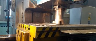
Connecting bases for milling machine 6M82. Trunk, earrings and spindle.
The connecting base consists of: trunk, earrings and spindle.
Trunk
The trunk serves to support the free end of the milling mandrel. For this purpose it is equipped with special pendants. The other end of the mandrel is attached to the spindle cone using a bolt. The trunk is attached to the guide profiles and can move along them thanks to a gear rack.
The trunk is attached to the frame at the front and back with two clamps. Both clamps must be fully tightened. The front protrusion of the trunk is usually equipped with two earrings, tightened with a nut (less often - one).
Attention! It is unacceptable to move earrings from one unit to another and “adjust” them!
Earring
Each earring has a bearing in the form of a bronze bushing. This bushing helps control the clearance in the plain bearing. It is very important to monitor the oil level in the inner recess of the earring. Sometimes, in order to give the trunk additional rigidity, it is equipped with support posts that are attached to the console. But in this case, vertical feeding is not allowed and the convenience of operation is lost.
Spindle
A spindle is a rigid shaft, hollow inside, onto which cutters are attached. The cutters are inserted into the conical hole using bushings and mandrels. The main engine of the machine ensures rotation of the horizontal spindle. It has 18 speeds (up to 1600 rpm), which are provided by a gearbox.
The vertical spindle is powered by a 2.8 kW electric motor located on the trunk. Its number of speeds is 9, maximum value is 1400 rpm. The number of rotations of the vertical shaft is regulated by the movement of gear blocks.
General form:
The standard equipment of this unit consists of the following elements:
- Bed.
- Console.
- Sled.
- Table.
- Trunk.
Upon individual order, the plant equips the installation with additional functional parts.
Location of components
bed
The basis of the cantilever milling installation is the bed. It is equipped with vertical and horizontal guide profiles. The consoles move along the first ones, and the trunk moves along the second ones. The gearbox was placed in the inner part of the body.
The side walls have closed recesses with electrical equipment. On the right is a switch with three modes:
- Automatic mode (for many identical operations)
- Handle feed (standard operation)
- Round table (for milling with platform rotation without interruption)
Console
The purpose of the console is to change the vertical position of the table. The engine built into the console is responsible for accelerated movements and feeds. The speed is controlled by the front handle.
Sled
This element can be moved with a rotating plate or with a work surface. This ensures cross feed. The table can move longitudinally along the guide profiles.
Table
The parts to be milled are mounted on the table. Moreover, they can be moved along the surface. The product is fastened with bolts screwed into the grooves of the table. In front there is also a groove for cams, which switch the longitudinal movement of the platform automatically.
Location and list of controls for the 6M82 cantilever milling machine
The installation is controlled using switches. There are three switches on a single panel:
- To rotate the spindle.
- For cooling pump.
- For input.
A separate unit for adjusting speeds is installed on the left side of the frame. The value shown on the dial means spindle rotation. Nearby there is a plateau with buttons. Three of them regulate the operation of the spindle (“start”, “stop” and “jog”). The fourth is called “Quick stop”, the fifth is the local lighting switch.
There is a handle installed under the dial that switches speeds. The sequence of actions is as follows:
The feed box control system (to the left of the console) includes a dial with table feed indicators, as well as a switching fungus.
The machine is equipped with handles and a flywheel for moving the table and console manually. There is also a mechanical feed control along and across the working platform. Quick rotation of the table is possible after the mechanical feed is turned on and the “quick stop” button is pressed.
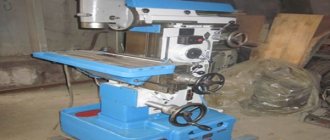
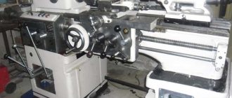
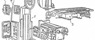
Machine 6M82 | Horizontal milling machines
Horizontal milling machines are characterized by a horizontal spindle (Fig. 35). A frame 2 is installed on the foundation plate 1, inside of which there is a main movement mechanism driven by an electric motor 3 and a gearbox 4. A console 5 is mounted in the vertical guides of the frame, which can move vertically along the frame guides. A transverse slide 6, a rotary plate 7, is installed on the horizontal guides of the console, and a longitudinal (working) table 5 is installed in the guides of the latter.
Securing workpieces on a 6M82 milling machine
Thus, a part mounted directly on a table, in a vice or fixture can receive feed in three directions. The presence of a rotating plate allows, if necessary, to rotate the desktop in a horizontal plane and set it to the required angle. Some horizontal milling machines do not have a rotary plate. In this case, they are called simple, in contrast to universal. The table feed drive is located inside the console 5 and consists of an electric motor 9, a feed box 10 and other mechanisms.
Rice. 35. Horizontal milling machine 6M82
Securing the tool on the machine
Milling chucks and short mandrels are inserted directly into the conical socket of the spindle 11 and secured with a long bolt 1 (a cleaning rod) passing through the hole in the spindle 2 (Fig. 36) 8 Long mandrels 3 Fig. 35. The horizontal milling machine 6M82 60 requires additional support, so one end of it is fixed into the spindle hole, and the second is placed in the suspension bearing 4 trunks. The trunk 12 (see Fig. 35) is located in the upper part of the frame 2. A suspension 13 with a center (on the left) or with a bearing (on the right) is installed in its guides. Two supports 14 can also be attached to the trunk, the lower ends of which are connected to the console. The supports serve to increase the rigidity of the console.
Rice. 36. Reception of securing cartridges and mandrels
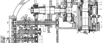
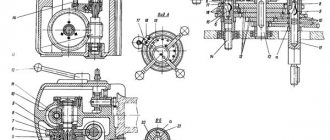
Kinemetic diagram of the 6M82 machine
In Fig. Figure 37 shows the kinematic diagram of the 6M82 universal horizontal milling machine. The drive of the main movement is borrowed from the electric motor 69 and is carried out by an 18-speed gearbox. Rotation from shaft 1 using gears 1-2 is transmitted to one of three pairs of wheels 3-4, 5-6 or 7-8. From here, one of the gears 9-10, 11-12 or 4-13 communicates movement to shaft IV, and the last one, along the chain of wheels 14-15 or 16-17, communicates to spindle V. The spindle speed is changed by switching wheels 3-5-7, 10- 13-12 and 14-16.
Rice. 37. Kinematic diagram of the universal horizontal milling machine 6M82
Feeding mechanism of the 6M82 machine
The feed mechanism drive is located inside the console. Electric motor 63, using gears 18-19, 20-21, rotates shaft VIII and then through gears 22-23, 24-25 or 26-27, 27-28, 29-30 or 31-32, rotation is transmitted to shaft X. Hence the movement shaft XI can be transmitted through a pair of wheels 33-34 (wheel 33 moves to the right to engage clutch 75) or through a bust consisting of wheels 35-36, 37-33 and 33-34 (in this case, wheel 33 occupies the position shown on the diagram). The wide wheel 34 is freely mounted on the shaft and transmits rotation to it when the clutch 64 is engaged. When the disc friction clutch 67 is engaged, the shaft XI can receive the rapid rotation necessary for rapid movements. The fast rotation chain consists of gear groups 18-19, 19-52 and 52-53. Clutches 67 and 64 are interlocked and have one control; When the first clutch is turned on, the second one is turned off and vice versa. The table feeds are carried out using screw mechanisms: longitudinal 54-55, transverse 56-57 and vertical 58-59. Nut 55 is fixed in the upper slide, nut 57 is in the console, nut 59 is in cabinet 66. The longitudinal feed chain connects shaft XI with lead screw 54. It consists of gears 38-39, 40-41-42, 43-44, 45 -46 (in the diagram, screw 54 is rotated 90° relative to the axis of wheels 44 and 45; its axis is perpendicular to the plane of the drawing).
The cross feed chain consists of gears 38-39, 40-41-42-47. The vertical feed chain includes gears 38-39, 40-41, 48-49 and 50-51. To turn the feeds on and off, couplings 62, 65 and 70 are used.
Similar materials
www.metalcutting.ru
Kinematic diagram
An electric motor is mounted in the console, which drives the gears. Gear wheels in the feed box adjust the working feeds. This is a mechanism of two blocks with three rims and one mobile gear equipped with a claw coupling. To prevent the mechanism from being overloaded, one of the shafts is equipped with an adjustable spring ball clutch.
Stages of making innings:
- The gearbox makes the console move.
- When the dog clutch is engaged, the revolutions are transmitted to the propellers through the wheels.
Each of the three lead screws is responsible for a specific feed direction (vertical, transverse and longitudinal). For the accelerated movement of the slide, console and table, intermediate wheels are responsible, which transfer revolutions to the gear wheel of the accelerated clutch. The clutch is located on one of the feedbox shafts.
Kinematic diagram of the 6T82G milling machine
The feed drive is carried out from a separate flange electric motor mounted in the console. Working feeds are adjusted using switchable gears of the feed box, consisting of two three-crown blocks and one movable gear with a cam clutch. On the last shaft of the box in the kinematic chain of working feeds, an adjustable ball spring clutch is provided, which protects the feed mechanism from overload.
From the last shaft of the feed box, the movement is transmitted to the console. Then, through a series of cylindrical and bevel gears mounted in the console and slide, one of the three lead screws is rotated by engaging the corresponding jaw clutch, and thus longitudinal, transverse or vertical feeds are carried out.
Switchable gears of the feed box allow you to get 18 different feeds with different gears.
The kinematic chain for accelerated (installation) movements of the table, slide and console is performed by transmitting motion from the engine through parasitic gears directly to the gear of the high-speed clutch mounted on the last shaft of the feed box.
The specified clutch is interlocked with the working feed clutch, thereby eliminating cases of their simultaneous activation.
Description of the electrical equipment of the 6M82 machine
The electrical appliances of the standard 6M82 machine provide three-phase power, voltage 380V and frequency 50Hz.
All electrical appliances are presented in the form of four panels and are hidden in the recesses of the frame.
The electrics are connected to the network using a handle on the left wall of the frame. The spindle is started by a button, and the direction of its operation is regulated by a switch.
The installation has two command devices. The first (1KA) is responsible for the longitudinal feed of the table (left-right), the second (2KA) is responsible for the vertical and transverse feed in five modes.
Changing operating modes occurs when the position of the handle is shifted. The system provides autonomous control of the cooling pump and local lighting of the installation. The coolant is supplied by an electric pump with a power of 0.125 kW and a rotation speed of 2800 rpm.
The high speed clutch is driven by a built-in electromagnet. As soon as rapid running is started, this magnet stops the dog clutch.
The electrical diagram of the machine shows that the existing electric motors are provided with zero protection, protected from short circuits and overload. The system also contains a number of blocking elements that protect electrical equipment from incorrect operation and, as a result, breakdown.
Description of electrical equipment
The electrical equipment of the 6M82 machine model operates on a current of 380 V with a frequency of 50 Hz. To power the control circuit, the current was reduced to 127 V, the lighting operates from a 36 V network. Overload protection is installed at the zero phase of the electric motor. Fuses prevent short circuits in the machine network.
Reference! Equipment for 220 V and 500 V voltages was produced for individual enterprises and for export.
There are niches in the frame for electrical equipment. Each has two panels connected into a common circuit. On the left is the handle to turn on the power to the entire unit. The spindle has a push-button control with a reversible rotation direction switch. The feed motor is activated by two control devices:
- longitudinal movement;
- lateral and vertical movement.
Operating modes are started in the electrical circuit of the control unit - by a start switch having 3 operating positions:
- automatic cycle;
- feed from handles;
- round table.
The electric pump pumping coolant is switched on. There is a switch for the light bulb on the local lighting lamp. The EB electromagnet is located on the high-speed friction clutch and turns it off when the mechanical feed is turned on.
Braking is carried out by a bias current directed by a selenium rectifier to the electric motor. Quick engagement of gear wheels is accomplished with a “push”. When switching speeds, a short-term reverse movement of the spindle occurs until the teeth engage.