Sometimes, during soldering, an extra pair of hands is not enough to hold the parts being soldered. For this purpose, you can use the so-called third hand (this is the name of a special soldering clamp). A third hand helps a lot, but soldering tools with loops sold in countless online stores lack flexibility. This article will teach you how to make a DIY third soldering arm with four clamps.
Here is a list of required parts and materials with links:
• Flexible bracket - link. • Alligator clip - link. • Epoxy glue - link. • Spray paint - link (optional). • Spade wood drill with a diameter of 12 mm - link. • Wood glue - link. • MDF board - link. • Clips or clamps.
If you don't want to read the article, you can watch a video that shows all the steps to make a solder holder.
Soldering fixtures, clamps and holders - making a third hand
Sometimes, during soldering, an extra pair of hands is not enough to hold the parts being soldered. For this purpose, you can use the so-called third hand (this is the name of a special soldering clamp). A third hand helps a lot, but soldering tools with loops sold in countless online stores lack flexibility. This article will teach you how to make a DIY third soldering arm with four clamps.
Here is a list of required parts and materials with links:
• Flexible bracket - link. • Alligator clip - link. • Epoxy glue - link. • Spray paint - link (optional). • Spade wood drill with a diameter of 12 mm - link. • Wood glue - link. • MDF board - link. • Clips or clamps.
If you don't want to read the article, you can watch a video that shows all the steps to make a solder holder.
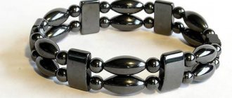
A selection of “third hands” - tripods and devices for holding small electronics, etc.
Hi all!
Electronics have recently become very shredded and it is not always convenient to do it yourself when working with small circuit boards, wires, etc. Sometimes outside help is needed to hold the board, solder a wire to it, replace some component, or take measurements. You can do without outside help using the so-called “third hand” - a device in the form of a tripod with clamps, magnifying glasses, lamps and other amenities collected in one place.
This collection contains only such devices, but in different interpretations.
So, let's begin.
1. The simplest device, but often found on the tables of craftsmen.
You can buy it here
An axis with two clamps and a magnifying glass are attached to the cast-iron frame with hinged joints. The connections allow you to rotate the crocodiles and the magnifying glass with five times magnification (diameter 60 mm made of glass) at the desired angle. The device is not the most advanced in terms of functionality, but probably due to its low price, it is often found on specialists’ desks in electronics repair shops. Approximate dimensions: 125*70*50
2. The next "third hand" is similar to the previous one, but gives one more degree of freedom - both the clamps and the magnifying glass can be raised and lowered along the tripod, adjusting the desired position and magnification.
You can buy it here
The lens here is also glass, but with a diameter of 90 mm. There is parking for a soldering iron and a tray for all sorts of small items.
3. Tripod with two swivel clamps, two interchangeable lenses, soldering iron parking and LED light on a flexible leg.
Link here
The lenses here are plastic, there are two of them. Diameter 90 and 21 mm, magnification 3.5 and 10 times, respectively. The five backlight LEDs can be powered either from 3 AA batteries or from the included 5 Volt power supply. The axle with clamps is movable - you can move it closer to the central post or move it forward.
4. It's an interesting third arm, but it doesn't allow you to mount the board vertically.
Check price
There is adjustment of the reach and tilt of the lamp and the axis with clamps. Two acrylic lenses with a diameter of 75 and 20 mm. The backlight is powered by 3 AAA batteries or USB. Dimensions 200*95*170 mm. For stability, a steel plate is built into the base. There is parking for a soldering iron.
5. The next fixture is the next version of the previous third arm.
Check current price
There are already three acrylic lenses and trays have been added for all small things, which is sometimes convenient. Lens diameters 72, 30 and 20 mm. By combining lenses and the distance between them, you can achieve good magnification. Illumination is provided by 10 LEDs powered by 3 AAA or USB elements
6. A tripod with a backlight on a flexible leg, hinged clamps and the ability to install the board at any angle.
Link to product page
The set includes three acrylic lenses. Lens diameters 90, 34 and 34 mm. Magnification 2.5, 7.5 and 10 times. Backlight power -3*AAA or supplied power supply. They come with two lenses, and the third is made in the form of an influx on the largest one.
7. The next device is distinguished by a powerful backlight group and a neat appearance.
You can buy it here
Here, 18 LEDs and three lenses with a diameter of 108 mm (main), 21 mm (second interchangeable) and 30 mm (third interchangeable), giving magnification of 2.5, 6 and 10 times, will help you see small components. Illumination in both the upper and lower lamps with lenses. Included in the kit is a power supply for the backlight or 2*AA, you will have to buy it yourself.
8. The next “third hand” does not have a backlight or magnifying glass, but allows you to fix the board or part in almost any position. It looks futuristic, but the reviews are positive.
Find out the price
Six flexible holders with crocodiles are fixed to the frame. There are trays for small fasteners. The base is made of aluminum alloy, the weight of the structure is 550 grams.
9. A similar option, but with a more reliable attachment to the table and adjustable backlight.
You can buy it here
There are four holders here instead of six. Lens diameter 60 mm, magnification three times. As many as 42 LEDs were used, and the light control has 11 positions. Powered by USB 5V/1.5A. The length of the holder legs is 240 mm, the length of the lamp leg is 400 mm.
10. The selection ends with a device that I have been using myself for two years now. It often helps a lot.
Find out the price
The axle with three clamps can be raised, lowered vertically, pushed towards the rack or pushed forward, and also changed the angle of inclination of all three clamps at the same time. There is parking for a soldering iron and it is done correctly, the soldering iron does not fall through. There is a backlight and most importantly: the kit includes three lenses and a handle. The lenses can be mounted on a tripod, or they can be connected to the handle and get three full-fledged magnifiers. In addition, the handle itself contains a pair of LEDs and a compartment for two AA batteries. Sometimes it's very convenient. Acrylic lenses with a diameter of 90, 75 and 37 mm. Magnification 2.5, 5 and 16 times. The tripod is very stable and comes with a power adapter for illumination or can be powered by 4 AA batteries. The lints are of good quality, without sagging, deformation, etc.
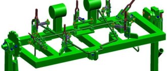
Universal clamping angle - the welder's third hand
Good day, lovers of making something with their own hands. In today's article we will take a closer look at how to make a useful construction tool. Namely, we will assemble a special clamp that allows you to connect various objects at an angle of 90 degrees, for convenient fastening (for example, for welding objects together). This homemade product is simple in structure, which makes it easy to build and incredibly reliable and durable. Yes, there are also budget factory analogues, but in our case, a homemade product will be both more practical and much more reliable than any factory analogue. Therefore, I recommend that at least every welder and carpenter assemble it. Well, well, I think there’s no need to delay with a long preface, let’s go.
For this clamp you will need the following, namely:
— Metal corner — Metal plate 3-5 mm thick — Thick hairpin — Nuts for the hairpin — Metal washers — Bolt — Some kind of enamel paint — Paper clip (clip) The following
tools will also be needed:
— Grinder with cutting and grinding discs — Welding machine with all necessary welding accessories for working with it - Drill with drills - Construction corner - Tape measure or ruler - Marker - Vise
Making a universal clamping tool:
First of all, you need to select a metal corner. In fact, the larger the corner you choose, the better, but a tool that is too heavy will be very inconvenient to handle, but a tool that is too small will not be able to cope with large tasks. Therefore, decide for yourself which things you work with more.
Having selected the necessary metal corner, you need to saw off a couple of segments of the same length from it. They should be approximately 20 centimeters long each; this size will be sufficient for any task, and the finished tool will not be bulky. Using a marker and tape measure, we mark the places to cut, then use a grinder to saw off the planned sections.
After you have sawed off the corners, it would be advisable to immediately sand them thoroughly to remove burrs and any corrosion that has formed on the metal, since this will be very problematic to do later after assembly.
Next you need to cut out a metal rectangle. It can be cut from a sheet of metal, the author had a suitable straight metal plate and used that. Here I would like to note that this part itself should be relatively thick and durable. Since it is this part that will bear most of the load, and if it bends, it will be very unpleasant and the tool will lose its functionality. We also grind this rectangle, like the corners earlier.
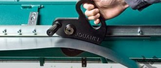
We proceed to welding the existing workpieces. The first step is to weld two corners together, or, to be more precise, not weld them, but simply fix them. This assembly stage is the most critical, since this unit requires increased precision. The two corners should touch each other with their tips at an angle of 90 degrees, as shown in the photo below. For this you also need a construction angle, thanks to which it is very convenient to check the angle.
The next step is to weld our metal plate to the corners. It is necessary to weld at the junction of two corners, so that this plate comes out of this 90 degree angle, and divide it in half (see photo). As you probably already guessed, it is impossible to weld our rectangle at such an angle, or it is possible, but then it will be on a different plane relative to the corners, and it will not look very good. Therefore, one of the ends of this plate must be trimmed so that it fits into place as required.
We apply the plate to the corners, using a marker we mark the corners that need to be cut. Then we clamp this very plate in a vice, take the grinder in our hands and saw off the marked corners on the plate.
Next, we weld the already prepared plate to its seat. In this case, it is necessary to weld as carefully as possible, thereby welding all the joints of the workpieces. Then you should definitely grind the welds so that it looks like a monolithic part.
We smoothly move on to the manufacture of the clamp itself, or more precisely, the “clamping head”, it is this that will reliably fix objects. For it you will need a small piece of metal corner and the same metal plate. We place a metal plate on our structure, as shown below, then place a corner on top perpendicularly, in the corner of the structure. As you can see, the plate sticks out beyond the corner; these extra parts need to be marked and then sawed off with a grinder.
We immediately measure the required length of the metal corner; it should be the same as the width of the corner used at the very beginning. Mark and saw off the excess length of the corner you took. As a result, we get two more blanks that need to be welded together and this should be done exactly as the author did it (see photo).
Let's move on to the next stage of assembling our homemade product, and for it you will need a hairpin, something thick and reliable (again, thick, but in moderation). It is necessary to ensure the operation of the mechanism thanks to this pin, and this should be done as follows. Namely, it is necessary to make a through hole at the edge, and due to the fact that the pin taken by the author is too wide, it came to narrow this end.
Next, assemble the sandwich. Namely, from the side where we turned the pin, we put on a washer, then a small metal rectangle, then another washer. And in order to prevent the last washer from flying off, we insert a paper clip or a so-called clip into the hole made in the pin. As you can see, the metal rectangle itself rotates freely around its axis, regardless of the pin, which is what was required.
After which this metal rectangle itself, mounted on a stud, must be welded to the corner made earlier, as it is shown below. Immediately after this, screw a couple of nuts onto the stud. These nuts must be welded to our base so that the stud rotates freely. As a result, we get the following, namely, when the pin rotates, the clamping angle moves forward and backward (depending on the direction of rotation).
For more convenient operation of the homemade product, it is necessary to make a handle. Our handle will be made of a long bolt of suitable diameter. In order to secure it to the stud, you need to do the following. We screw a couple of nuts onto the stud at the very end, weld them and then drill a hole in them with a diameter slightly larger than the diameter of the bolt.
Then we insert a bolt into the hole made and, so that it does not fall out from the back side, we screw a nut onto it and fix it with a weld point. As a result, we get a handle that can move longitudinally if necessary.
Let's move on to the last final stage of assembling our homemade product. Namely, for painting and assembly. Of course, you don’t have to paint your homemade product, but you’ll agree that a well-painted tool is much nicer than a rusty, oxidized one. And whatever you say, paint will extend the life of your tool.
All is ready! As a result, we have come up with a useful tool that will come in handy for you many times and make your homemade work easier.
Here is a video from the author of the homemade product:
Well, thank you all for your attention and good luck in future DIY projects!
Source
Become the author of the site, publish your own articles, descriptions of homemade products and pay for the text. Read more here.
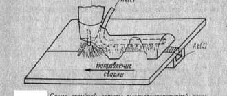
Manual soldering in three hands: making a homemade holder
Manual soldering is an operation the need for which arises quite often. Soldering requires not so many different devices and materials, so many home craftsmen can do it. However, when performing it, one more – third – hand is usually missing. Someone, when soldering boards, tinning wires or other operations, purchases a special holder for themselves, which costs about 500 rubles in the store. However, this device can easily be made with your own hands, spending less than a hundred on everything.
Binocular magnifier for soldering with head mount. Small DIY
A magnifier for SMD soldering is one of the necessary things for a radio amateur. But finding an inexpensive and convenient one is not so easy. Nevertheless, such goods do exist. For those who are interested in the topic, please cut So, why did the idea of such a purchase arise? I once had a magnifying glass with a headband and fixation on the bridge of the nose. A bit like this one. In terms of using it as a magnifying glass, everything was fine. But the constant pressure on the bridge of the nose made its long-term use completely uncomfortable. Then I bought magnifying glasses. I thought - since they are lighter, the previous problem will not exist. But no. I didn't like long-term use either. In the wake of the hype, I bought an electron microscope like this - https://aliexpress.com/item/item/1005001494859759.html According to the picture, everything was not bad, there were no delays on the screen when moving the soldering iron. But I was once again convinced of what I wrote about more than once. For comfortable soldering you need a stereo image. You can adapt to soldering under an electronic one, but it is completely uncomfortable. In general, I played with it and sold it. If you take a higher budget, you can buy a good binocular microscope. This is, of course, the best option. But the prices there are more or less adequate, from two to three hundred dollars and then they fly off into space. On the other hand, at home I don’t solder that often, but at work I already have everything I need. Therefore, I doubted the need for these expenses. One day I saw something similar by chance and decided to buy it and try it out. Let's take a closer look at it.
Magnifier parameters:
Mount - head-mounted with an adjustable headband Material - ABS for magnifying glass and acrylic for lenses Magnification - 1.2X 1.8X 2.5X 3.5X Weight - 170g Size - 240*200*125mm Lighting (flashlight) - removable Power - 3AAA
Everything is delivered in a bright cardboard box. On the box there is a photo of the magnifying glass itself, the characteristics of the lenses. The model is called MG81001-F.
Inside the box there is a magnifying glass mount, removable lighting, a set of lenses in a case, and a plug for a removable mount.
Box with lenses.
Closer.
Lens.
Lens material: acrylic. It scratches a little even when wiped with microfiber. On the other hand, they can be easily polished if necessary. The seller's website contains the following information:
Magnifications distance to viewed objects: 1.2X: 520-620mm 1.8X: 230-320mm 2.5X: 150-250mm 3.5X: 80-120mm
Actually, this is not true. Using a ruler, I measured the range of distances to the object when the eye comfortably focuses. It turned out like this:
1.2x: 12-30cm 1.8x: 8-16cm 2.5x: 6-12cm 3.5x: 5-10cm
Below are examples of photographs through lenses. dip8 chip. Some photos may be a little blurry - it is difficult to hold the phone at the required distance from the lens and the lens itself according to the Crop ruler is the same size in the photo.
1.2x 12cm
1.8x 8cm
2.5x6cm
3.5x 5cm
Now let's look at the magnifying glass mount. General form. A soft bow that fits to the forehead.
Lens mount.
Change sizes to suit different head circumferences.
Turning part tightening nut.
Bottom view of the lens mount. You can also see the hole for pushing the flashlight out of the mount.
Actually the flashlight itself.
There are two small neodymium magnets at its base. Quite strong.
Mounting slots for AAA batteries are also visible. The lever moves in a vertical direction relative to the body, the head of the flashlight itself moves up and down, left and right, relative to the lever. The light can be directed in any direction.
Let me digress a little from the topic. In fact, this form factor of the flashlight turned out to be very convenient to use. Recently I was repairing a shower stall, I removed the front wall and crawled under the pan. There is little room to turn around. With a regular flashlight it was very difficult to direct the light where needed. The family didn't help much either, because... They constantly had to tell them where to shine. I attached such a lantern with magnets to the nearest iron leg of the shower, directing the light where I needed it so I could work. I also use it periodically when I need to highlight something locally or work on something far from the working light.
LED with lens.
If you remove the plastic plug inside (located on the left), you can see the rotating mechanism and wires going to the top. There we will then remove some of the excess plastic in order to place the converter board. But that's later. In the DIY part of the review.
The upper half of the part with the LED is unscrewed. The board, LED, lens, microswitch (without fixation) are visible.
The board itself.
A microcircuit filled with compound is not a current stabilizer. Regular trigger. Yes, about the light. He's terrible
1. There is no current stabilization. As the batteries drain, the light becomes dimmer and dimmer. 2. The LED is bluish, with a poor spectrum.
This is what we will redo. I have already written several times that the backlight (for most Chinese backlights) needs to be converted either to LN or to LEDs with a warm color temperature and good CRI. Why? LEDs with a large blue hump in the spectrum have a peculiarity - they shine brightly, but, oddly enough, small details are poorly visible. This is due to the focusing characteristics of the eye in different parts of the spectrum. There are different studies on this matter. I once cited something similar eyepress.ru/article.aspx?24403 You can go straight to the results. Well, I also wanted to give up 3AAA and use two Ni-Mh.
So, the DIY part.
Remodeling scheme.
The converter used is MT3608. I used GW SBLMA1.EM-HQHS-A535-L1N2-65 LEDs. Don't be alarmed by the names . They are actually quite common. Osram just labels them that way. Datasheet docs.rs-online.com/535b/0900766b813fd7d9.pdf
Color temperature 4000K Nominal current 65mA Maximum current 150mA Nominal voltage 2.9V CRI 85 Efficiency 159 lm/W Viewing angle 150 degrees Luminous flux 35 lm
The current through the diodes is set to 52mA. If you look at the table in the datasheet, the total luminous flux from the three diodes will be about 85 lm. More than enough for soldering. Maybe even a little less. Two Ni-Mh batteries are used. The charge lasts for about two and a half hours. This may not seem like much, but in fact, if you turn on the backlight only while soldering, it’s enough for a full day. And it even stays for the next one. It suits me.
The converter used is the common MT3608 www.mikrocontroller.net/attachment/212877/MT3608.pdf https://aliexpress.com/item/item/32371184340.html
It seems that it was specially designed for two Ni-Mhs (just kidding, of course). When the voltage drops to 2V, the brightness drops sharply by about one and a half times. Those. We know that the batteries will soon run out. Turns off at 1.8V (0.9V per element). Those. We will never discharge batteries below the threshold. An attentive reader will ask, why is there a resistor in the circuit? Yes, it's not needed. I just added it while I was testing the scarf with the power supply on the CC. Then it stayed like that
Signet. I made larger polygons for better heat dissipation.
And now the assembly itself. We remove the button and install a suitable slide switch. Fix with epoxy.
We cut the board in the shape of the old board and etch it with LUT.
We remove the excess plastic where the inner cover above the lever was. We make a slot for the rope to pull out the batteries. Now we will have two of them.
Converter board.
We solder the commutations to the battery terminals. We insert the board (it fits perfectly).
Next, I did a test on the LED board - I applied the required voltage and covered the board with paper for half an hour to see the heating.
Everything is fine. There is no overheating. In a real case the temperature will be even lower.
Assembled.
Let's check. Shines evenly and brightly. It is visible much better than with a Chinese diode.
Results.
How do I use lenses? 1. 1.2x and 1.8x lenses are most common. Why? After all, their increase is the smallest. There is one point here. I can solder smd without lenses at all, but this makes my eyes very tired. Low magnification lenses allow you to maintain a wide range of focusing distances with much less strain on your eyes. Well, it’s not always necessary to consider the smallest details. 2. 2.5x - from time to time, because The soldering distance to the component is small. When you need something important or very small components. Or look at the inscriptions that are difficult to read. 3. 3.5x - rare. Look at small laser markings and find any problem areas.
Pros. 1. Convenient design. Doesn't cause any discomfort. 2. Large range of adjustment of the headband. 3. Removable flashlight. Really convenient not only for soldering, but also for some housework. 4. A set of lenses is enough for different types of work.
Minuses. 1. Lenses are easily scratched. You need to be careful. Ideally, of course, I would like it to be made of glass. But the Chinese don't do that. 2. Lighting is initially no good. It needs to be redone. But after the rework everything is fine.
Well, according to tradition, Muska is a cat.
Additional information
Copying materials
The use of any materials posted on the Labuda.blog website is permitted only if you provide a direct indexed link (hyperlink) to the copied page of the Labuda.blog website. A link is required regardless of the full or partial use of materials.
ATTENTION! We do not allow third-party resources to embed links to image files hosted on our hosting. All images are protected from hotlinking. Regular copying (saving) of images to third-party resources is permitted!