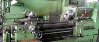
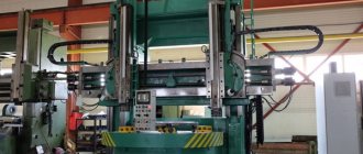
The TV-320 universal lathe, on which you can perform various technological operations for processing metal workpieces, belongs to the category of high-speed equipment, used primarily to equip tool and instrument-making enterprises.
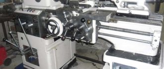
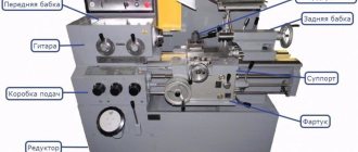
Appearance of the TV-320 machine
The technical capabilities of the TV-320 lathe allow you to effectively perform the following technological operations on it: processing external as well as internal surfaces, turning cones, cutting metric threads, performing operational work, etc.
Machining on the TV-320 can be performed with a tool mounted on the front or rear tool holder. Such a mechanism is installed on the caliper if the need arises.
The characteristics of this unit allow processing using high-speed turning, as well as combining technological operations. The TV-320 design has a special mechanism with which you can change the feed parameters without stopping the machine.
There are several modifications of the lathe of the model in question, these include:
- TV-4;
- TV-6;
- TV-16.
How does the TV-320P machine differ from the equipment of the model in question?
The turning unit, which is marked with the letter “P”, differs from the basic TV-320 model by increased processing accuracy, which is ensured by the features of its design. There are increased demands on the manufacturing accuracy of the main structural components of the machine, which include its frame, lead screw, spindle assembly, front bearing and gears included in the kinematic chain used for thread cutting.
Such characteristics of the TV-320P lathe predetermine its use as equipment for performing semi-finishing and finishing work. This unit is not recommended for rough turning operations.
TV-320 controls
In order for the machine in question, which corresponds in its accuracy to the requirements of GOST 1969-43, to maintain its characteristics for a long time, the permissible feed speeds on it are reduced, as well as the maximum rotation speed of the spindle assembly - up to 1400 rpm (on the TV-320 machine this parameter corresponds to 2000 rpm).
Purpose and application
The operating instructions for the TV-320 lathe define the list of permissible operations:
- Preliminary, semi-finishing and finishing processing of workpieces made of steel and cast iron, from the outside and inside;
- cutting internal and external threads (metric, inch, modular, pitch);
- manufacturing parts for various tools;
- precise turning of cone-shaped surfaces.
The TV-320 screw-cutting lathe is capable of successfully working on the following metal:
- steels of grade 45 or 30 (workpiece diameter does not exceed 50 mm);
- gray cast iron with a hardness not higher than HB 160 (in this case, the diameter of the workpiece can reach 70 mm).
In terms of its capabilities, the TV-320 screw-cutting lathe has gained quite wide popularity. It is used to solve a wide range of problems in metalworking, automotive and agricultural engineering.
General view of the TV-320 machine
Where higher processing accuracy is required, the modernized TV-320P machine is used.
Higher precision characteristics can be achieved through the use of parts with a higher accuracy class in the machine.
About the design of the TV-320 machine
The design of the TV-320 lathe consists of the following elements:
- gearbox;
- feed switch box;
- headstock with spindle assembly;
- tailstock;
- a drive that ensures the execution of feeds;
- apron;
- cooling system drive;
- caliper carriage.
Kinematic diagram of the machine (click to enlarge)
Schematic diagram of the machine
TV-320 frame design
All structural elements that make up the TV-320 screw-cutting lathe are placed on a frame made of cast iron and has a box-shaped shape. Diagonal ribs in its inner part increase the rigidity of this load-bearing unit.
In the upper part of the equipment's supporting frame, mounted on two cast iron stands, there are three prismatic and one flat guides. The lathe slide moves along two of them (prismatic), and the tailstock moves along the other two (prismatic and flat). In the left cabinet of the frame there is a gearbox of the unit, a cabinet with electrical equipment, a motor responsible for driving the main movement, and a container for coolant.
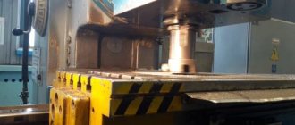
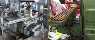
The bed of the TV-320 machine, prepared for grinding guides
Design features of the machine
TV 320 is manufactured according to the classic design of a screw-cutting lathe. However, it has a number of serious design differences from its analogues.
Steel panel radiators were invented at the end of the last century. This was facilitated by new developments in the technology of producing steel sheets, welding, and painting. Consumers wanted a radiator with higher performance than cast iron. Steel radiators have begun to carve out their niche in the heating equipment segment.
Firstly, this is the high-speed sharpening system already mentioned above and changing feeds without interrupting work. Also, the structural features of this high-precision machine include:
- Installation of two incisors simultaneously with a change in position;
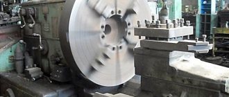
- Mounting on the faceplate for cartridges with a thickness of 120 and 150 mm;
- The presence of sliding bearings that limit friction;
- Autonomous oil supply system;
The structure of the headstock of the machine
The headstock (spindle) of a lathe is made of cast iron. In its front part there is a gear selector mechanism, and in the rear part there is a feedbox drive mechanism that operates in forward and reverse directions.
The spindle of the unit is a hollow pipe, at the front end of which there is a conical neck. A plain bearing is installed in the front support of the spindle assembly, and a high-precision angular contact bearing is installed in the rear support. The cutting forces that act on the spindle assembly along its axis are absorbed by the thrust bearing.
Front spindle support with plain bearing
The spindle assembly elements must meet the following technical specifications:
- axial clearance between the elements of the rear support – 0.01–0.015 mm;
- runout in the axial direction – no more than 0.01 mm;
- the gap between the bearing and the spindle in the diametric direction is 0.015–0.03 mm.
Headstock drawing
The mechanism, which is used to change the direction of feed without changing the rotation parameters of the spindle assembly, is located in the headstock - on its left side. The rolling bearings of the headstock can be adjusted, for which special nuts are used.
Technical specifications
Kinematic diagram of the machine
Objectively, the best source of information regarding a screw-cutting lathe is the passport. But the problem is that it is difficult to find the original passport from the manufacturer. In the age of the Internet, all information can be obtained there. Therefore, do not worry if you do not have a paper operating manual and a manual for your screw-cutting lathe in your hands.
Your task in the process of purchasing and starting to operate the machine is to compare the nominal and reference technical characteristics.
Let us note the most significant technical parameters with which you should compare the data relevant for the screw-cutting turning unit you purchased with the TV 320 index.
- The dimensions of the device for turning and screw-cutting operations are 161 by 95 by 125 centimeters;
- Unit weight - 900 kg;
- The maximum diameter of a workpiece that can be processed on a screw-cutting lathe depends on its location. When installing under the support, the maximum diameter of the part is 320 mm, and if installation is carried out above the frame - up to 170 mm;
- The length of the workpiece that the TV can process is 320 - 500 mm;
- The incisors have a cross-section of 20 by 20 millimeters;
- The through hole of the spindle has a diameter of 26 mm. This allows the machine to use rods with a diameter of up to 25 mm;
- The number of steps for forward and reverse rotation of the spindle is the same and amounts to 18 units;
- Regardless of the direction of rotation of the spindle head, its rotation speed is adjustable within the range of 36-2000 rpm;
- The movement of the carriage is identical for working on a screw, shaft and by hand - 580 mm;
- A screw-cutting lathe has the same number of transverse and longitudinal feeds. It is 16 units;
- The maximum tailstock quill offset is 90 millimeters;
- Transverse displacement - up to 15 millimeters.
Electric motors
A pair of electric motors is installed on the turning-screw-cutting device of the model in question. Each of them is responsible for performing strictly assigned functions.
Both electric motors have a robust design, excellent performance and a long service life.
- Main electric motor. It has a power of 2.8 kW. This electric motor functions as a drive for the spindle head of a screw-cutting lathe.
- Additional electric motor. Its role is played by a motor installed in an electric pump. This pump is designed to operate a liquid cooling system. The power of this electric motor is 0.125 kW. These parameters are more than enough to ensure effective cooling of screw-cutting equipment components.
It is worth adding that in order to improve the quality of the processing performed, stops for longitudinal movement were installed on the machine.
Additionally, the turning and screw-cutting equipment received a protection system against overloads and a handle locking system. Their functionality is not satisfactory, as evidenced by the corresponding reviews from the owners of this turning and screw-cutting device.
Despite all the objective shortcomings of the machine, it has a number of positive characteristics. Its technical parameters, reliability and functionality allow it to remain relevant several decades after production ceased. But it’s up to you to decide whether it’s worth equipping your workshop with such a unit.
How does the equipment support work?
The support of the TV-320 machine (as in any other turning equipment) simultaneously solves two problems:
- the cutting tool is fixed on it;
- This unit moves the turning cutter in two directions (longitudinal and transverse).
Support for lathe VT-320
The structural elements of the caliper are:
- cross slide;
- top slide;
- carriage (longitudinal slide);
- turning part.
The caliper carriage moving in the longitudinal direction, as well as the cutting slides, is driven manually and by a mechanical drive. An additional cutting head can be installed on the slide, for which two T-shaped grooves are provided in their design. The amount of transverse movement of the cutting slide is adjusted using two stops. In order to facilitate the calculation of the parameters of the transverse movement that the caliper makes along the limb, a ball stop is provided in the design of the latter.
Adjustable cross feed stop is convenient for serial processing of parts
Machine apron
The main purpose of the apron, which is located in the front part of the lathe, is to communicate the rotational movement of the lead screw and the lead roller to the support. The special mechanism with which the caliper is equipped eliminates the risk of simultaneous activation of the lead screw and roller, which protects them from premature failure. The inclusion of the uterine nut is associated with the position of the handle responsible for switching the feed of the TV-320. This activation can only be performed if this handle is in the middle position.
If overloads occur during processing, which may be due to an increase in cutting force or jamming of the cutting tool, the so-called falling worm mechanism is activated in the apron of the TV-320 machine, automatically turning off the feed.
Apron of the TV-320 machine
Technical potential of metalworking machine
In accordance with the passport, the turning unit has the following technical capabilities:
- the maximum value of processed products is 320 mm;
- permissible length of the cultivated workpiece – 500 mm;
- level of centers above the supporting frame – 155 mm;
- number of rotation speeds of the main shaft – 18;
- number of feeds: 16 – perpendicular, 16 – axial;
- spindle rotation speed – 36–2000 rpm;
- spindle opening diameter – 260 mm;
- number of cutting metric threads – 19;
- minimum and maximum thread pitch – 0.25/5;
- accuracy group, in accordance with GOST – N;
- equipment weight – 900 kg;
- installation parameters, mm - 1800x950x1250.
Lathe TV-320
Structure of the gearbox
Using a gearbox, rotation from the main electric motor is transmitted to the spindle unit of the TV-320 lathe. There are two blocks of gears on the three shafts of the unit’s gearbox, providing 9 different spindle rotation speeds.
The gearbox housing can move along special grooves, which allows you to adjust the tension of the belts that transmit rotation to the spindle assembly. To move the box, you need to loosen the bolts that secure it to the guides. In order for the box shafts to successfully carry axial and radial loads, ball and roller bearings are installed in their supports, the gaps in which are adjusted using special screws and nuts.
Belts driving the spindle
The standard equipment of the machine allows you to cut metric threads. Other thread types require an additional set of gears, selected according to the table on the guitar cover.
Replacement machine gears
Device
Bed.
Photo 1: bed.
A machine weighing 900 kg, on which high-precision machining of metal parts is carried out, has reasonable requirements for stability as a guarantee of safe operation. From this point of view, not a single consumer made any complaints about the TV 320 box-shaped cast iron frame. The rigidity of the frame inside is further reinforced by powerful diagonal ribs. It is held in place by a pair of cast iron stands. At the top there are four guides: three of them are prismatic, and the last one is flat. Let's look at the main nodes.
Front (spindle) headstock.
Photo 2: headstock.
Solid cast iron.
The spindle is a cone-shaped neck on an empty pipe. In its front support there is a plain bearing, and at the rear there is another bearing - a high-precision angular contact bearing. And there is a third one - the thrust bearing. The speed switch is located in front of the spindle head, and the feed box is placed behind it. There are two working directions. Changing the direction (direct - reverse and vice versa) does not affect the set amount of rotation and is carried out by a mechanism on the left in the headstock, the operation of the bearings of which is regulated by special nuts.
Turners consider the spindle to be a technically satisfactory unit.
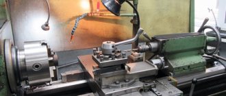
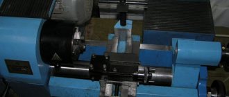
Caliper.
Photo 3: caliper.
The support is the place where the cutting mechanism is fixed, the carriage of which, after fastening, can be moved longitudinally and transversely.
Longitudinal movement can be mechanical or manual. The inner two T-shaped grooves are provided for installing an additional cutter. The transverse movement is performed by a cutting slide, and its value is adjusted by two stops: a ball stop and a transverse one. The first makes it easier to check indicators, and the second makes it easier to process a series of parts.
Apron.
Photo 4: apron.
Located in front. A device that eliminates the risk of breakage when the lead screw and roller are unexpectedly turned on at the same time is placed in the caliper. The master nut is only activated when the switch handle is in the middle.
Overloads in the apron cause automatic shutdown: the “falling worm” is activated.
Gearbox.
Photo 5: gearbox
Thanks to this structural mechanism (three shafts and two gear blocks), the spindle assembly rotates (nine speeds). You can adjust the tension of the belts that transmit rotation by moving the box body along the provided grooves.
By loosening the fixing bolts, you can move the box.
The clearances of the bearings located in the box shaft supports are adjusted by screws and nuts. This makes the shafts easier to bear loads (axial, radial).
The standard equipment is designed to apply metric threads. And additional gears - a different thread. You can select the one you need using the instructions. To do this, you will need a table on the cover of the guitar.
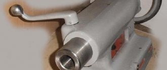
Tailstock
The only way to move it longitudinally is manually. It may be necessary when processing a long workpiece, the right edge of which can be supported in this way and the cutting tool can be secured with an eccentric mechanism.
By moving the headstock transversely, the conical surfaces are processed. And longitudinal movement is provided by a screw connected to a nut, which is rotated by a flywheel. The quill moving inside the headstock is fixed by two clamping pins connected to the control handle.
If you need to repair the tailstock yourself, you should first watch the video:
Additional accessories.
What and how you can install is worth watching in the video:
How the tailstock of the machine works
The tailstock of a lathe, which can only be moved longitudinally by hand, is used to support the right end of long workpieces during processing and to secure the cutting tool. The tailstock is secured to the frame using an eccentric mechanism.
Tailstock drawing (click to enlarge)
The tailstock can also move in the transverse direction, which allows processing of conical surfaces on the machine. A screw driven by a flywheel is responsible for the longitudinal movement of the tailstock along the frame guides. This screw is connected to a nut. The position of the quill, which moves inside the tailstock, is fixed by means of two clamping pins connected to the control handle.
What technical capabilities does the machine of this model have?
Let's look at the technical characteristics of the TV-320 lathe.
- The distance between equipment centers is 500 mm.
- The maximum length of a part processed by turning is 500 mm.
- The maximum diameter of parts that can be processed on the machine: above the surface of the bed - 320 mm, above the surface of the support - 170 mm.
- The diameter of the through hole in the spindle assembly is 26 mm.
- The diameter of the rod that can be inserted into such a hole is 25 mm.
- The number of spindle rotation speeds is 18.
- The number of longitudinal and transverse feeds is 16 each.
- The machine spindle speed is 36–2000 rpm.
- Feed limits: longitudinal – 0.03–0.49 mm/rev, transverse – 0.012–0.18 mm/rev.
- The conical part of the spindle is made in the Morse-4 category, the quills are made in the Morse-3 category.
- Model dimensions (length, width, height): 1800x950x1250 mm.
- Equipment weight – 900 kg.
Technical characteristics of the TV-320 machine
Considering all the above characteristics, the capabilities of the TV-320 lathe are quite impressive, as evidenced by numerous positive reviews about this equipment.
Technical characteristics and dimensions
Another advantage of the TV-320 unit is its small size. This allows the equipment to be used even in small workshops. Machine weight – 2,900 kg. Dimensions in length, width, height in cm 180x95x120.
The main drive of the machine is an electric motor with a power of 3 kW and a nominal speed of 1430 rpm.
Main technical characteristics:
- the headstock shifts in a range of 18 speeds;
- The tailstock quill can be moved by 90 mm;
- a nut is used to secure the tailstock;
- the rod blank can have a maximum diameter of 25 mm;
- the feed unit has 16 stages of adjustment in the longitudinal and transverse directions;
- the length of the workpiece when turning it is limited - 50 cm;
- spindle seat diameter – 26 mm;
- the largest size of lateral movement of the caliper is 28 cm;
- longitudinal maximum travel of the caliper – 58 cm;
- number of revolutions per minute on the spindle – 36-2000 rpm.
The unit does not have a spindle braking system.