The predecessors of the 16k20 lathe, produced by Soviet machine builders, were a number of screw-cutting lathes equipped with a gear gearbox. These metal-cutting machines bore names from DIP-200 to DIP-500. The abbreviation of the names spoke of the desire of the leadership, supporting the slogan of the 1st Five-Year Plan to catch up and overtake the leaders of capitalism.
The number following the letter part of the name corresponded to the height of the centers of the machine relative to the bed in mm. Machines with such names were produced from 32 to 37 of the last century. The change of names occurred as a result of the development and approval of the “Unified System of Symbols for Machine Tools” (USUS). According to the adopted document, the founder of the generation changed the name of DIP-200 to 1D62. However, the outdated name is still used as a general name for lathes with center heights of about 200 mm.
Purpose of the machine
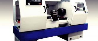
In the early 70s, Soviet Mash, after several modifications of the DIP models, launched the production of turning screw-cutting 16k20. Which in 1972 received a gold medal at the international fair in Leipzig.
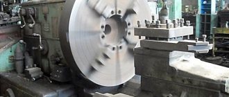
Intended for a variety of turning operations, it made it possible to turn various simple and complex surfaces in the chuck, on the faceplate and in centers. And besides, boring, facing, cutting, and cutting all kinds of threads. Its design was so successful that in the USSR it was long considered the best equipment of its type. Screw-cutting machines differ from other representatives of the turning group in their greater versatility.
Therefore, their use is more rational in small-scale or piece production.
Factory markings and designations
In accordance with the ESUOS, the designation of a machine or its index consists of several numbers and letters. The first character is the group number. Turning equipment is assigned No. 1. The second indicates the variety or type of device in the group, for example, 6 corresponds to universal turning and screw-cutting equipment. Next is a number characterizing the most important dimensional parameter. For lathes it is the height of the centers above the base plane.
The letter located between the first and second digits of the index indicates that the model was obtained by improving its predecessor. The placement of the letter at the end of the designation indicates that this model is the result of a modification of the base one. The letter located in the middle is a sign that this is a basic model and serves as the name of the generation. Thus, the index 16k20 has the basic model of a new generation “K” screw-cutting lathe with a center height of 200 mm.
Precision designation
According to operating tolerances, turning equipment is usually divided into the following categories:
- N – normal accuracy;
- P – increased;
- B – high;
- A – especially high.
- C – especially accurate (master).
Design features
Appearance
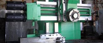
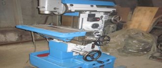
Initially, the 16K20 screw-cutting lathe was developed to perform standard operations - turning the surfaces of parts, forming threads of various types. For this purpose, the installation of blanks is provided in the center and on the chuck mechanism.
To analyze the capabilities of the equipment, it is recommended to study the passport and photo. The design features are a rigid frame, made in the shape of a box, and hardened, ground guides. These components are installed on a monolithic base. Thanks to this arrangement, the productivity of the 16K20 series machine is significantly higher than that of its earlier counterpart - 1K62.
In addition to the improved kinematic diagram, the following technical characteristics of the 16K20 machine can be noted:
- spindle head. Makes it possible to choose one of four rows of speeds with different limit options;
- flanged front end of the spindle. It is mounted in precision rolling bearings. This allows you to avoid making additional adjustments while the machine is operating;
- output shaft design. It is connected to the gearbox using adapter gears. Thanks to them, the caliper can move over a wide range;
- tool holder design. It provides reliable fixation of the cutting tool. This is a prerequisite when processing workpieces made of special carbide steels.
Additionally, you should study the description of the caliper passport. In addition to improved mechanics, it contains additional measuring rulers and an original feed switch mechanism.
The optimal option for using the 16K20 machine is in small-scale production and repair shops. This is explained by the accuracy class “H” and the standard surface roughness V6b.
Specifications
- Accuracy group – N.
- Center height (mm) – 215.
- Ø standard cartridge – 200 or 250 mm.
- The speed range of rotation of the spindle shaft in the direct direction (rpm) is 12.5–1.6*103. Adjustment discrete number of gears 24.
Moreover, both in the forward and reverse directions there are 2 gears with a frequency of 500 and 630 rpm. Therefore, some sources talk about 22 forward and 11 reverse transmissions.
- The speed range of rotation of the spindle shaft in the reverse direction (rpm) is 19–1.9*103. Adjustment discrete number of gears 12.
- Feed range (mm/rev): along the axis – 0.05–2.8; across 0.025–1.4.
- The pitch range of metric threads is 0.5–112 mm.
- The range of modular thread pitches is 0.5–112 modules.
- The range of inch thread pitches is 56–0.5 threads/inch.
- The range of pitch thread pitches is 56–0.5 pitches.
Limit parameters
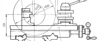
- The maximum permissible diameter of a “disc” workpiece turned over the bed is 400 mm.
- The maximum diameter of the “shaft” type workpiece turned over the caliper is 220 mm.
- Limit length of the workpiece to be turned (mm) – 710, 1000, 1400, 2000.
- Limit length of turning (mm) – 645.935, 1335, 1935.
- The Ø of the “rod” type workpiece is no more than 50 mm.
- The weight of the workpiece fixed for processing in centers (no more) is 460, 650, 900, 1300 kg.
- The weight of the blank fixed for processing in the chuck (no more) is 200 kg.
- The force developed by the feed unit at the stop (no more) is 800 kgf along the axis, 460 kgf across it.
- The force developed by the feed unit on the cutter (no more) is 600 kgf along the axis, 360 kgf across it.
Screw-cutting lathe 16K20
16K20
The 16K20 high-precision universal lathe is designed to perform various turning operations, including cutting metric, inch, modular, and high-precision pitch threads.
Technical characteristics 16K20
Technical characteristics of the screw-cutting lathe 16K20:
The largest diameter of the product installed above the frame, mm ... 400
The largest turning diameter above the bottom of the transverse slide, mm ... 220
The largest diameter of the processed rod, mm ... 50
Distance between centers, mm ... 710, 1000, 1400, 2000
Maximum turning length, mm ... 645.935, 1333, 1935
Spindle rpm range... 12.5 - 1600
Feed limits, mm/rev:
- longitudinal ... 0.05 - 2.8
- transverse ... 0.025 - 1.4
Steps of cut threads
- metric, mm ... 0.5-112
- inch (number of threads per 1″) ... 56-0.25
- modular (in modules) ... 0.5-112
- pitch (in pitches) ... 56-0.25
Spindle hole diameter, mm ... 52
Main electric motor power kW. … 10
Controls of the machine 16K20
The controls of the 16K20 screw-cutting lathe are shown in Fig. 14. Kinematic diagram of 16K20 is shown in Fig. 15.
Rice. 14. Controls of a high-precision screw-cutting lathe 16K20
Handles:
1 — setting a number of spindle speeds; 2 - settings of spindle speeds, 3 - settings of normal, increased thread pitch and position when dividing multi-start threads, 4 - settings of right and left threads, 5 - settings of feed amount and thread pitch, 6 - settings of the type of work - feed and type of thread being cut , 7 - setting the feed rate and thread pitch and disabling the feed box mechanism, 8 - controlling the friction clutch of the main drive (interlocked with handle 16), 11 - turning the rack and pinion gear on and off, 14 - turning on the feed, 15 - turning the lead screw nut on and off , 16 — control of the friction clutch of the main drive (interlocked with handle 8); 18 - attaching the tailstock to the frame, 19 - gripping the tailstock quill, 20 - controlling the mechanical parameters of the carriage and cross slide of the caliper, 22 - manually moving the cutting slide of the caliper, 23 - rotating and securing the indexable cutting head, 25 - manually moving the transverse slide of the caliper ; buttons: 9 — spool for lubrication of the carriage guides and the transverse slide of the caliper, 12 — turning on and off the electric motor of the main drive, 21 — turning on the electric motor for driving the fast moves of the carriage and the transverse slide of the caliper; flywheels: 10 - manual movement of the carriage, 17 - movement of the tailstock quill; 26 — adjustable coolant supply nozzle; 13 — bolt securing the carriage to the frame; switches: 24-local lighting, 27 - machine load indicator, 28 - coolant supply electric pump switch, 29 - signal lamp, 30 - input circuit breaker.
Kinematic scheme 16K20
The kinematic diagram of the machine is shown in Fig. 70.
Main movement
The main movement in the machine is the rotation of the spindle, which it receives from electric motor I through a V-belt drive with pulleys 2 - 3 and a gearbox. A double-sided friction clutch 6 is installed on the receiving shaft II. To obtain direct rotation of the spindle, the clutch is shifted to the left, and the rotation drive is carried out through the following chain of gears: 4 - 8 or 5-9, 10-13 or 11 - 14. or 12-15, shaft IV, wheels IS -21 or 19 - 22. spindle V. From shaft IV, rotation can be transmitted through selection 16 - 23 or 17 - 24, 25-27 and 26-22 when moving block 21-22 on the spindle to the right. The technical characteristics of the 16K20 make it possible to obtain 12 options for wheel engagement when transmitting rotation from shaft IV directly to the spindle and 12 options when transmitting rotation through the overdrive.
The spindle is reversed by moving the coupling 6 to the right. Then the rotation from shaft II to shaft III is transmitted through gears 7-28, 29-12, and the latter receives reverse rotation.
Rice. 70 Kinematic scheme 16K20
Feed movement
The feed mechanism communicates the movement of the caliper along four kinematic chains: screw-cutting, longitudinal and transverse feed, rapid movement. Rotation of shaft VIII from spindle V is transmitted through gears 20-32, and when cutting threads with an increased pitch from spindle V through the pitch increasing link: wheels 22-26, 27-25, 23-16 or 24-17 and through wheels 16- 33.
From shaft VIII, the movement is transmitted through a reversing mechanism with wheels 30-35 or 31-34-35 to shaft IX, then through replaceable wheels abd or abcd to the input shaft X of the feed box. By switching clutches 116, 60. 43 and 50, as well as rearranging block gears 57 and 58, 45 and 46, 47 and 48, 52 and 53, various combinations of connecting wheels 36...64 of the feed box are carried out. From the output shaft XV of the feed box, rotation can be communicated either to the lead screw 61 or to the lead shaft XVI. In the first case - through clutch 60, in the second - through wheels 59-62, 63-66, overtaking clutch 67 and wheels 68-64.
Screw chain. When cutting a thread, the caliper is fed from the lead screw 61 through the uterine nut fixed in the apron. The required thread pitch can be obtained by switching gears and couplings in the feed box or by installing replacement wheels a, b, c, d on the guitar. In the latter case, clutches 116 and 60 disable the feedbox mechanism. To prevent breakdowns due to accidental overloads, clutch 117 is used.
Longitudinal and transverse feed of the caliper
To transmit the movement of the 16K20 lathe to the apron mechanism, the chassis shaft XVI is used. A gear 65 slides along it along the keyway, transmitting rotation through wheels 69, 70, 71 when clutch 72 is engaged and a worm pair 73-74 to shaft XVII.
To obtain longitudinal feed of the caliper and its reversal, one of the cam clutches - 77 or 84 is turned on. Then the rotation from shaft XVII is transmitted by gears 75-83 - 76 and 79-92 or 85 - 92 to shaft XVIII and then to rack and pinion wheel 94, which, rolling along a rack 95 fixedly connected to the machine bed, it carries out longitudinal movement of the caliper.
Transverse feed and its reversal are carried out by turning on clutches 87 or 90. In this case, from shaft XVII through gears 75-86 and 88-93-98-96 or 75-86-89 and 91-93-98-96, rotation is transmitted to screw 97, which imparts movement to the transverse carriage of the caliper.
Installation movements of the support of a 16K20 screw-cutting lathe, the tool slide and the tailstock quill. To carry out rapid (installation) movement of the caliper, the running shaft XVI is subjected to rapid rotation from the electric motor 113 through the V-belt drive 114-115. In this case, the caliper feed mechanism through the feed box does not need to be turned on, since an overrunning clutch 67 is installed in the drive chain of the drive shaft. Using lead screws 109 and 112, you can manually move the cutting slide and the tailstock quill manually through the wheels 110-111. The machine can be equipped with a mechanical drive of the slide. In this case, from the running shaft XVI through the apron mechanism, wheels 65...98, the wheel 99 of the shaft XIX is connected, and then through the wheels 100...108 the movement is transmitted to the screw 109 of the cutting slide.
Through a V-belt drive 118-119 from the shaft / a lubrication pump 120 is connected.
Setting up the 16K20 kinematic diagram for thread cutting comes down to selecting the gear ratios of feed boxes and other mechanisms, which is done by switching the corresponding levers. An exception is the cutting of particularly precise threads or threads with non-standard pitches. The final link of the thread-cutting chain is the lead screw 55 (see Fig. 69) and the uterine nut, so the adjustment equation can be written in the following form (keeping in mind the single-throw screw):
1 rev.sp. i- tв = tн (8.1)
where tн is the pitch of the thread being cut; tв—lead screw pitch; i is the gear ratio of the kinematic chain from the spindle to the lead screw.
Multi-start thread cutting
Technical characteristics of 16K20 allow you to cut multi-start threads. In multi-start threads, the pitch tn is understood as the distance between the parallel sides of the profile of two adjacent turns. Therefore, to obtain a thread of a given pitch, the feed mechanism must, in one revolution of the workpiece, move the caliper by the amount of thread stroke s = K tн where tн is the number of starts of the thread being cut. This type of thread is cut on lead screws, multi-start worms and other parts.
Multi-start threads are cut in two ways: after cutting the first thread, the workpiece is turned by part of a turn 1/k; Having previously opened the screw-cutting chain or leaving the workpiece motionless, move the tool along with the cutting slide longitudinally by the thread pitch tn. Then the next entry is cut, etc. The 16K20 machine has a special dividing device for cutting multi-start threads. It consists of a ring with a score, mounted on the headstock body, and a disk with divisions, mounted on the spindle and having 60 divisions on the periphery. After cutting the first pass, the spindle must be rotated by a number of divisions equal to 60/k. This device allows you to cut threads with a number of starts of 2, 3, 4, 5, 6, 10, 12, 15, 20, 30, 60. On machines that do not have a dividing device, a driven dividing plate is used.
Processing of shaped surfaces
If in the described copying device a shaped ruler is installed instead of a conical ruler, the cutter will move along a curved path, processing the shaped surface.
Rice. 70 Schematic diagram of the operation of a hydraulic copying support
For processing shaped and stepped shafts, the 16K20 machine is sometimes equipped with hydraulic copying supports, which are most often located on the rear side of the machine support. The lower slide of the support has special guides, usually located at an angle of 45 to the axis of the machine spindle, in which the copying support moves.
In Fig. 70 shows a schematic diagram explaining the operation of the hydraulic copying support. Oil from pump 7 enters the cylinder, rigidly connected to the longitudinal support 5, on which there is a transverse support 2. The latter is connected to the cylinder rod. Oil from the lower cavity of the cylinder through the slot / in the piston enters the upper cavity of the cylinder, and then into the follower spool 6 and into the drain. The follower spool is structurally connected to the caliper. Probe 4 of spool 6 is pressed against copier 3 (in area ab) using a spring (not shown in the diagram). In this position of the dipstick, oil flows through spool 6 to the drain, and transverse caliper 2 moves backward due to the difference in pressure in the lower and upper cavities. At the moment when the probe is in area be, it is recessed under the action of the copier, overcoming the resistance of the spring. In this case, the drain from spool 6 is gradually blocked. Since the area in the lower cavity is larger than in the upper, oil pressure will force caliper 2 to move downwards.
In practice, there are a variety of models of lathes and screw-cutting lathes, from tabletop to heavy-duty ones, with a wide range of sizes. The largest processing diameter on domestic machines ranges from 85 to 5000 mm with a workpiece length from 125 to 24000 mm.
Adjusting the machine 16K20
The video shows the process of setting up the machine and adjusting the spindle assembly.
Similar materials
Electrical circuit diagram
There are 3 operating voltages in electrical equipment:
- Motor power supply –380V.
- Automatic - 110V.
- Workplace lighting – 24V.
List of machine electrical components:
- R – Load indicator E38022 (ammeter ~20A).
- F1 – Current protection circuit breaker AE-20-43-12.
- F2 – Automatic AE-20-33-10.
- F3, F4 – E2782—6/380 – fuse link.
- F5 – TRN-40 – electrothermal protection.
- F6, F7 – TRN-10 – electrothermal protection.
- N1 – safety light-signal device UPS-3.
- N2 – NKSO1X100/P00-09 – electric lamp with S24-25 lamp.
- N3 – KM24-90 – switching lamp.
- K1 – PAE-312 – remote magnetic starter.
- K2 – PME-012 – remote starter.
- KZ – RVP72-3121-00U4 – time delay relay (Limit of operation of the main motion electric motor without load).
- K4 – RPK-1-111 – engine starter.
- M1 – Main motion electric motor 4A132 M4, rated power 11 kW.
- M2 – 4А71В4 – electric motor (accelerated displacement of the caliper).
- M3 – Electric pump PA-22 (emulsion supply).
- M4 – 4A80A4UZ – asynchronous electric motor.
- S1 – VPK-4240 – limit switch (Distribution device door).
- S2 – PE-041 – rotary control switch (unlocking S1).
- S3 and S4 – PKE-622-2 – push-button control unit.
- S5 – MP-1203 – microswitch.
- S6 – VPK-2111 – push-type limit switch.
- S7 – PE-011 – rotary control switch.
- S8 – VPK-2010 push-type limit switch.
- T – TBSZ-0.16 – step-down transformer.
Diagram of lathe controls
Description of the electrical circuit
The start of the electric motor of the main drive M1 and the hydraulic station M4 is carried out by pressing the button S4 (Fig. 1), which closes the day of the coil of the contactor K1, switching it to self-power. The main drive electric motor Ml is stopped by pressing button S3. The electric motor for rapid movement of the carriage and support M2 is controlled by pressing a push button built into the apron handle and acting on the limit switch S8. Starting and stopping the electric cooling pump M3 is carried out by switch S7. The operation of the electric pump is interlocked with the electric motor of the main drive M1, and it can only be turned on after closing the contacts of the starter K1.
To limit the idling speed of the main drive electric motor, the circuit has a short-circuit time relay. In the middle (neutral) positions of the friction clutch engagement handles of the main drive, the normally closed contact of the limit switch S6 is closed and the time relay K3 is turned on, which, after a set time delay, will turn off the main drive electric motor with its contact. It is strictly prohibited to adjust the time delay in the operating state of the relay.
The electric motors of the main drive, the rapid movement drive of the carriage and support, the electric cooling pump and the transformer are protected from short circuit currents by automatic switches and fuses.
Protection of electric motors (except for electric motor M2) from long-term overloads is carried out by thermal relays.
Zero protection of the electrical circuit of the machine, which protects against spontaneous activation of the electric drive when the power supply is restored after a sudden shutdown, is carried out by magnetic starter coils.
Exploitation
A slight increase in the gaps between mating parts, leading to a decrease in processing accuracy, is eliminated by adjustment. Significant wear requires repair or replacement of parts. To reduce wear and prevent mechanical breakdowns during operation, it is necessary to follow the rules of equipment care.
Main movement
Since the cutting process occurs due to the rotational energy of the blank, it is usually called the main movement of the turning group equipment. The main movement drive consists of a single-speed three-phase asynchronous electric motor equipped with a manual gearbox.
Feed movement
The translational movement of the tool, ensuring contact of the cutter with the surface of the workpiece at the desired point, is called the feed movement. Its drive switches depending on the task being performed and can be manual or mechanical due to the power of the main drive.
Feeds and main movement are the main movements of the turning group equipment.
Longitudinal and transverse feed of the caliper
To move the support along and across the axis of rotation of the blank, longitudinal and transverse slides are used, respectively. Each of them is equipped with its own guides and screw drive. Transverse feed allows you to change the depth of cut and, in combination with longitudinal feed, form the required surface of the part.
Multi-start thread cutting
The selection of replacement gears is done in the same way as for cutting a single-start thread. With the difference that to determine the thread progress, its pitch must be multiplied by the number of starts. If the drive of the upper slide of the caliper is not too worn, division into approaches can be done by setting the latter parallel to the axis of rotation of the part. After cutting the groove in the first pass, the cutter, removed from the metal, is returned to its beginning. Then the cutter is retracted to a distance equal to the thread pitch from the first start. After which they begin to cut the second one.
Processing of shaped surfaces
The production of products with complex surfaces is possible in several ways:
- Using conventional cutters using alternating longitudinal and transverse manual feed. The method has low accuracy and productivity. Requires well-developed execution technique.
- Special shaped cutters. The method is highly productive, but requires non-standard cutters.
- With ordinary cutters using copiers or circular feed devices. The method is highly productive, but requires manufacturing or equipment.
Brief description of the main components of the 16K20 machine
Motor installation
When the torque on the spindle decreases (see Table 1, clause 12.1.2), first of all you should check the tension of the main drive belts. If the belts are not tensioned enough, then you need to loosen the screws 1, and by smoothly rotating the nut 7 counterclockwise, lower the under-engine plate 6 until the required belt tension is achieved, after which screws 1 are tightened until they are tight.
The tension of the lubrication system pump drive belt is carried out by raising the tank 2, for which you need to loosen three screws 3 (one is shown in the drawing), with which the tank is attached to the under-engine plate 6.
Main drive friction clutch control mechanism (Fig. 34)
The design of the mechanism eliminates the possibility of turning on or off the friction clutch when accidentally pressing handles 12 and 24, which are interlocked as follows.
When operating handle 12, handle 24 repeats the first operations. Switching off is possible with any of the handles. If the clutch was engaged by handle 24, then disengagement can also be done by handle 12, only if this handle is first rotated to the appropriate operating position and then returned to the neutral (middle) position to disengage.
Gearbox (replacement gears)
The gearbox (replaceable gears) serves to transmit rotation from the output shaft (axis I) of the spindle head to the output shaft (axis II) of the feed box by installing combinations of replaceable gears in accordance with the diagrams in the table (Fig. 10). The machine can be set up to cut various threads.
Replacement gears K and N are mounted on splined shafts and secured with bolts 9 through washers 8.
Intermediate gears L and M are installed on the splined sleeve 10 of the axis 13, secured with a key in the required location of the groove of the bracket 3, which is fixed with a nut 6.
At the ends of the replacement gears K, L, M, N are marked (see packing list), the number of teeth z and the module m.
When fixing bracket 3 and axle 13, you need to install replacement gears with minimal radial clearance.
We must not forget about regular lubrication (see paragraph 6.2. “Lubrication chart”) of the replacement gears and bushing 10, which is lubricated through the oiler cap 12.
Bed, racks, lead screw, drive shaft and fast movement drive of the caliper
The tension of the drive belt for fast movements of the caliper is carried out by adjusting screw 3, which is locked with nut 2.
When cleaning the lead screw 13 and the drive shaft 14, it is necessary to remove the shields 9 and 10. To do this, you need to loosen the screws 19 and remove the shields from the side of the rear bracket 18.
Prevention and repair
Daily care activities
Before starting work:
- Inspection of the machine.
- Lubricate the lead screw and shaft.
- Controlling the amount of oil.
- Switching on with checking nodes without load.
During operation:
- Switch feeds and gears only after the moving units have finally stopped.
- When working with cast iron or abrasive materials, cover the guides with thick cloth.
After the end of working hours: turn off the power supply, remove the shavings, wipe with a rag soaked in kerosene, and lubricate the open guides with oil.
Malfunctions and their elimination
| Symptoms | Cause | Correction method |
| Ovality of the part or hole being bored. | Blank runout in the cartridge. | Boring of jaws. |
| Quill play or weak fastening of the thrust headstock. | Adjusting or repairing the quill. | |
| Hole axis offset. | Misalignment of spindle shaft and tailstock. | Adjustment. Or repair with adjustment. |
| Significant cone of cylindrical parts. | Mismatch between the centers of the spindle shaft and the thrust head. | Adjustment. |
| Worn caliper or bed guides | Adjustment or repair. | |
| Dimensional instability during trimming. | Axial play of the spindle shaft. | Replacing rotation bearings. |
A slight increase in caliper clearances can be eliminated by adjusting the wedges in the transverse or upper slide guides, and the adjustment screws in the rear guide of the longitudinal slide. Then, moving the slide to the maximum distance, make sure that it moves smoothly. Leaks in the screw drive of the cross slide are eliminated by adjusting the screws located behind the tool holder platform.
Repair of machine 16K20. Typical repair work performed during scheduled repairs
During the period between repairs, the machine must be subjected to six inspections, four minor repairs and one medium repair within the time limits specified in the recommended schedule of planned repairs (Fig. 42).
It should be taken into account that the greatest efficiency in using a machine can be ensured by rational alternation and frequency of inspections and scheduled repairs, carried out taking into account the operating conditions specific to each individual machine.
Categories of machine repairability:
- mechanical part - 12;
- electrical part - 8.5.
Machine inspection
External inspection without disassembly to identify defects of the machine as a whole and in units.
Checking the strength and density of fixed rigid connections (base with foundation; bed with base; headstock; feed box with bed; carriage with apron; pulleys with shafts, etc.).
Opening the covers of units for inspection and checking the condition of the mechanisms.
Removing play in the screw pair of the cross slide drive.
Checking the correct switching of spindle speeds and feeds.
Adjustment of the friction clutch of the main drive and the spindle band brake.
Checking the condition and minor repairs of the lubrication system.
Checking the condition, cleaning and minor repairs of enclosing casings, shields, etc.
Identification of worn parts that require restoration or replacement during the next scheduled repair.
Inspection before major repairs
Work performed during inspections before other types of repairs and, in addition, identifying parts requiring restoration or replacement, sketching or ordering drawings of worn parts from assemblies undergoing disassembly.
Note. During the inspection, those of the listed works are performed, the need for which is determined by the condition of the machine.
Minor lathe repair
- Partial disassembly of the spindle head, feed box, apron, as well as other most contaminated components. Opening covers and removing casings for internal inspection and washing of other components.
- Cleaning the mounting surfaces for fixtures on the spindle and tailstock quill without dismantling the latter.
- Checking the gaps between shafts and bushings, replacing worn bushings, adjusting rolling bearings (except spindle bearings), replacing worn ones.
- Adjusting the main drive friction clutch, adding discs, adjusting the spindle band brake.
- Removing burrs from gear teeth and splines.
- Replacement or restoration of worn fasteners and adjusting parts of tool holders.
- Scraping or cleaning of adjusting wedges, clamping bars, etc.
- Cleaning the lead screw, lead shaft, transverse and tool slide drive screws of the caliper.
- Cleaning and washing the seating surfaces of the cutting head.
- Checking the operation and adjusting the levers and handles of controls, blocking, locking, safety mechanisms and limiters; replacement of worn crackers, pins, springs and other parts of the specified mechanisms.
- Replacement of worn parts that are unlikely to withstand use until the next scheduled repair.
- Cleaning nicks, burrs, burrs and scratches on the rubbing surfaces of the bed guides, carriages, caliper slides and tailstock.
- Repair of enclosing casings, shields, screens, etc.
- Repair and flushing of the lubrication system and elimination of leaks.
- Regulating the smooth movement of the carriage and caliper slide; tightening the wedges of the clamping bars.
- Checking the condition and cleaning of gear couplings.
- Checking and repairing pneumatic equipment and cooling systems; eliminating leaks.
- Identification of parts requiring replacement or restoration during the next scheduled repair.
- Checking the accuracy of machine installation and selectively other accuracy parameters.
- Testing the machine at idle speed at all speeds and feeds, checking for noise, heating and on the workpiece for accuracy and cleanliness of processing.
Note. For minor repairs, those of the specified works are performed that are caused by the condition of the machine being repaired, with the exception of the work provided for in the last three paragraphs, which must be performed in all cases.
Average repair of a lathe 16k20
- Check for accuracy before disassembly.
- Measuring the wear of rubbing surfaces before repairing base parts.
- Partial disassembly of the machine.
- Washing, wiping parts of disassembled units, washing, cleaning of dirt from undisassembled units.
- Monitoring the rigidity of the spindle assembly (see paragraph 13.1.5).
- Replacement or restoration of worn bushings and rolling bearings.
- Replacing or adding friction discs and replacing the spindle brake band.
- Replacement of worn gears and couplings.
- Restoration or replacement of worn screw pairs of the caliper slide drive and tailstock quill.
- Replacement of worn fasteners.
- Replacement or restoration and adjustment of adjusting wedges and clamping bars.
- Restoring the accuracy of the lead screw (by cutting).
- Checking and cleaning unworn parts left in the machine mechanisms.
- Repair of the coolant supply pump and fittings.
- If the hinge mechanism of the lamp NKS 01 x 100/POO-03 wears out, unscrew the base, turn it counterclockwise 90° and secure it again.
- Repair of the lubrication system pump, equipment and fittings; repair or replacement of oil indicators, gaskets, plugs and other elements of the lubrication system.
- Correction by grinding or scraping guide surfaces in need of repair if their wear exceeds the permissible level.
- Repair or replacement of protectors on the carriage, caliper slide, tailstock.
- Repair or replacement of enclosing panels, casings, screens, etc.
- Assembling repaired components, checking the correct interaction of components and all machine mechanisms.
- Painting external non-working surfaces with putty.
- Running in the machine at idle speed at all speeds and feeds.
- Check for noise and heat.
- Checking the machine for compliance with accuracy standards.
Overhaul of lathe 16K20
- Checking the machine for accuracy before disassembling.
- Measuring the wear of rubbing surfaces before repairing base parts.
- Complete disassembly of the machine and all its components.
- Washing and wiping all parts.
- Inspection of all details.
- Clarification of a previously compiled (during inspections and repairs) list of defective parts requiring restoration or replacement.
- Restoration or replacement of worn parts.
- Cooling system repair.
- Replacing the lubrication system pump and repairing it.
- Grinding or scraping the guide surfaces of the bed, carriage, caliper slide, tailstock.
- Replacement of protectors on the carriage, caliper slide, tailstock.
- Assembling all machine components, checking the correct interaction of components and mechanisms.
- Puttying and painting of all unfinished surfaces in accordance with the finishing requirements of new equipment.
- Running in the machine at idle speed at all speeds and feeds.
- Check for noise and heat.
- Check the condition of the foundation, correct it and install the machine in accordance with section 4 of this manual.