16.03.2020
- What is spindle speed and frequency?
- Types of spindles by speed
- How to determine spindle speed
- Calculation of spindle speed of a lathe or milling machine
- Common mistakes when choosing cutting modes
- Recommendations for choosing a cutting mode
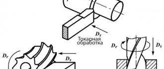
When choosing a processing mode for a part, a specialist needs to equally take into account both the performance of the equipment and the cleanliness of the finished surface. The balance between them directly depends on parameters such as feed speed and spindle speed of a lathe or milling machine.
Let us consider the characteristics in as much detail as possible, because they are especially important in the conditions of modern multitasking technology. One single control program can include contour cutting, engraving, and expansion of through holes, including plastic, metal, wood, and composite workpieces that differ in structure, size, and cutting resistance. Therefore, it is simply necessary to correctly regulate the input data - in order to avoid burns, roughness, and premature dulling of the working edges.
We will pay attention to everything related to the setup.
AC generation
In addition to standard generators, inverters and phase splitters are used to produce alternating current.
Inverter
This is a device with the help of which direct current is converted into alternating current. During this process, the output voltage also changes. The device circuit is an electronic generator of a sinusoidal pulse voltage of a periodic nature. There are options for inverters that operate with a discrete signal. Inverters are used for autonomous power supply of equipment from constant voltage batteries.
Phase splitter
Another way to get multiple phases from a signal is to split it into several phases. This is done using a phase splitter. Forced processing of digital or analog signals is used both in radio electronics and power electrical engineering.
To supply power to three-phase asynchronous motors, a phase splitter based on them is used. To do this, the windings of a three-phase motor are connected not by a star, but in a different way. Two coils are connected to each other in series, the third is connected to the midpoint of the second winding. The motor is started as a single-phase one, after acceleration, an EMF is induced in its third winding.
Interesting. In the case of phase splitting using this method, the phase shift between windings 2 and 3 is not 1200, as it should ideally be, but 900.
How to connect a frequency converter
If the cable for connection is 220 V with 1st phase, a “triangle” circuit is used. You cannot connect a frequency converter if the output current is higher than 50% of the rated value.
If the power cable is three phase 380 V, then a “star” circuit is made. To make it easier to connect power, contacts and terminals with letter designations are provided.
- Contacts R, S, T are intended for connecting the power supply in phases.
- Terminals U, V, W serve as the motor connection. To reverse, just change the connection of the two wires to each other.
The device must have a block with a ground connection terminal. More details on how to connect are here.
Angular frequency, period and angular velocity
It was already noted above that an important property of any rotational movement is the time during which one revolution is completed. This time is called the rotation period. It is designated by the letter T and measured in seconds. The formula for period T can be written in terms of angular velocity ω. The corresponding expression looks like:
The reciprocal of the period is called frequency. It is measured in hertz (Hz). For circular motion, it is convenient to use not the frequency itself, but its angular analogue. Let's denote it f. The formula for angular rotation frequency f is:
To calculate the angular frequency, you need to know the period of rotational motion.
Comparing the last two formulas, we arrive at the following equality:
This equality means the following:
- the formulas for angular frequency and angular velocity coincide, therefore these quantities are numerically equal to each other;
- Like speed, frequency shows how much angle in radians a body rotates in one second.
The only difference between these quantities is: angular frequency is a scalar quantity, while speed is a vector.
Related Articles
iForget ― 08/01/2021 | No comments yet
Reverse emulsifiers: use in the oil industry
Contents1 Lack of emulsions2 Inverse emulsions: what they are3 Emulsifiers4 Inverse emulsion in the oil industry As a drilling fluid in the oil industry
iForget ― 07/30/2021 | No comments yet
What is a rack test?
iForget ― 07.29.2021 | No comments yet
Buy quality copper powder
iForget ― 07.29.2021 | No comments yet
Why are wood-burning sauna stoves so popular?
iForget ― 07.29.2021 | No comments yet
The main stages of marble floor restoration
iForget ― 07/28/2021 | No comments yet
Standard BMW head unit for cars
iForget ― 07/28/2021 | No comments yet
The main advantages of using granite blocks
iForget ― 07.26.2021 | No comments yet
Decorative panels for apartment interior design
Recommendations for choosing cutting modes
There are several typical situations in which general recommendations can be used.
Spindle speed too high
Sometimes the minimum machine speed is still too high. This is usually observed when processing hard materials with large diameter cutters. The following solutions can be used:
- Replace the high-speed steel cutter with a carbide one, if possible, with a coating that operates at elevated temperatures.
- Reduce the diameter of the cutter. This will reduce the peripheral speed at which the cutting edge moves.
- Use HSM technology. High-speed machining allows higher spindle speeds and feed rates without increasing cutting tool wear. The first pass is made to the full width of the cutter, and all subsequent passes are made to ¼ of the diameter.
Feed speed too slow
In situations where the displacement drives cannot provide the required feed rate, you can proceed as follows:
- Reduce the spindle speed down to the minimum permissible power.
- Use a cutter with fewer teeth. This solution gives good results when working with viscous materials, since the conditions for chip removal from the machined surface are improved. Replacing a cutter with 3 teeth (entries) with a single-flute one actually means increasing the feed rate by 3 times (for each tooth).
- Use a larger diameter cutter.
Chip sticking when milling aluminum
Due to its relatively low melting point, aluminum tends to stick to the surface of the cutter. Many novice milling operators try to solve this problem by adjusting spindle speeds or travel speeds. As a result, the optimal cutting mode for the cutter becomes suboptimal for the enterprise owner: the processing speed turns out to be too low.
Take the test
Working with deep holes
If the depth of the hole is 6 or more times its diameter, it is considered deep. Inexperienced machine operators often encounter problems such as tools moving off the axis and breaking. There are several techniques that will allow you to perform processing accurately and without loss:
- Use drills, not cutters. If possible, they should have parabolic grooves, which provide better chip removal.
- Supply coolant under pressure. The liquid will flush the chips out of the hole.
- If possible, perform sequential processing with two drills with different diameters: go through half the depth of the hole with a smaller diameter and drill out to the drawing. Then go through the hole to the end.
- When working with one drill, remove it from the hole as often as possible to remove chips.
- Increase the feed speed so that the chips form a continuous spiral.
How to mill grooves?
When milling the ends of parts and the internal surfaces of grooves with cylindrical cutters, it is important to choose the correct ratio of the width and depth of the material being removed in accordance with the maximum speed capabilities of the machine. As the milling depth increases, the load on the grooves is distributed more evenly, but at the same time a stronger deflection of the cutting tool is observed
In addition, the conditions for chip removal worsen. As the width of the material being removed increases, it is possible to increase the spindle speed. However, there are some frequency limits at which the material removal rate begins to drop.
The only way to obtain the optimal combination of these two parameters is to test the machine in different modes. In this case, the material of the “test” and “working” blanks must be the same.
MULTICUT employees have devoted a lot of time to studying the processing modes of different materials. The choice of the basic configuration of machines of our own production was carried out taking into account the experience gained. The company's employees are ready to provide consulting and practical assistance in mastering the equipment and choosing optimal cutting modes. Anyone can work on a working MULTICUT machine in the demonstration center and receive advice from experienced craftsmen. You can get advice and information by calling the contact number.
Selecting cutting modes
To select a cutting mode, it is necessary to correctly select its main elements, that is, to determine and take into account the most favorable indicators of the values of these modes:
- Obtaining a technologically permitted feed rate. This is necessary to use all the power of the machine.
- Obtaining economical cutting speed. Helps to rationally use cutting elements.
After miscalculations, it is necessary to carry out checks using formulas or tables. They make it clear how the selected elements correspond to the power of the machine on which the metal will be cut, and the power of its drive is also determined. Checks are especially necessary if rough wiping work needs to be done.
Power of rotating objects
To calculate such a system, use the formula:
N = M * w = (2π * M* n)/60,
Where:
- M – moment of force;
- w – angular velocity characterizing rotation;
- n is the number of revolutions that an engine or other device makes in 60 seconds.
The information provided is used taking into account the intended purpose and actual conditions. Thus, in thermodynamics it is necessary to remember that the efficiency of the system depends on the ambient temperature. The heat loss of the heater is estimated by the corresponding power per unit surface area. The same is done when solving mechanical problems to calculate thrust, efficiency, and other operating parameters. As a rule, it is necessary to compensate for friction with a special coefficient.
In electrical circuits, current limits the resistance of the conductor. For short distances at low power, careful calculations are not necessary. However, the highway project necessarily contains the corresponding calculations. Based on the results obtained, conclusions are drawn about average annual economic indicators. It should be remembered that it is necessary to take into account the distortions that reactive loads add when working with alternating voltage.
Calculation of cutting forces
Calculation of cutting forces is needed to determine the effective cutting power and select an electric motor with the appropriate characteristics. We calculate cutting forces during milling using the formula:
de is the main component of the cutting force, daN;
– milling width, mm;
– number of cutter teeth;
– cutter diameter, mm;
– spindle rotation speed;
The calculation is carried out under the condition of processing a steel workpiece from MPa:
Next, according to the obtained cutting speed, we determine the cutting force:
Where ; mm; ; ; ; ; mm; mm/rev; ; mm;
Cyclic speed (reversal)
A scalar quantity that measures the frequency of rotational motion is called cyclic speed. This is the angular frequency, which is not equal to the angular velocity vector itself, but to its magnitude. It is also called radial or circular frequency.
Cyclic rotation frequency is the number of body revolutions in 2*π seconds.
For AC electric motors, this frequency is asynchronous. Their rotor speed lags behind the rotation speed of the stator magnetic field. The value that determines this lag is called slip - S. During the sliding process, the shaft rotates because an electric current arises in the rotor. Slip is permissible up to a certain value, exceeding which leads to overheating of the asynchronous machine, and its windings may burn out.
The design of this type of motor differs from the design of DC machines, where a current-carrying frame rotates in the field of permanent magnets. The armature contained a large number of frames, and many electromagnets formed the basis of the stator. In three-phase AC machines the opposite is true.
When an asynchronous motor operates, the stator has a rotating magnetic field. It always depends on the parameters:
- mains frequency;
- number of pole pairs.
The rotation speed of the rotor is in direct relation to the speed of the stator magnetic field. The field is created by three windings, which are located at an angle of 120 degrees relative to each other.
Spindle speed
Drilling equipment and its technological capabilities
9 spindle speeds
2 automatic spindle feeds
Overload clutch
Work table with height adjustment mechanism based on rack feed 420x300mm
Working surface base 320x320
Fig.2
Radial drilling machines
The radial drilling machine belongs to the category of universal ones, which is why it has become very popular in production. Its main purpose is to process holes. Capable of performing the entire range of basic operations typical of radial drilling machines - drilling and reaming. It can also be used for countersinking. The basic operations also include the operations of reaming, trimming ends, cutting threads using taps, etc.
The range of operations performed by a radial drilling machine can be significantly increased by using fixtures and special tools. For example, the use of appropriate equipment on a 2n55 radial drilling machine makes it possible to turn internal grooves, cut round plates from sheets and many other operations that are normally performed on boring machines.
The radial drilling machine 2n55 uses preselective control of speeds and feeds, and easy hydraulic control of the spindle friction. It is possible to disconnect the spindle from the gearbox; there are reliable hydraulic clamps of the column and drilling head, which can work both together and separately. All controls of a radial drilling machine are located in a small area. All of the above can significantly reduce auxiliary time. If frequent tool changes are required when working on a radial drilling machine, machine manufacturers recommend using a quick-change chuck, and when cutting threads, a safety chuck for taps.
The 2C550 radial drilling machine (Fig. 3) is designed for processing holes in medium and large parts. The 2C550 drilling machine performs the following types of work: drilling, countersinking, reaming, facing and threading. The 2C550 radial drilling machine is effectively used in individual, small-scale and mass production.
Rice. 3 Radial drilling machine 2C550. Specifications
| Magnitude | 2S550 |
| Drilling range in steel, mm | 3-50 |
| Cutting thread range | M3-M33 |
| Distance from the spindle axis to the column, mm. -minimum -maximum | 330 1230 |
| Distance from the end of the spindle to the working surface of the base, mm. -minimum -maximum | 225 1200 |
| Sleeve movement on the column, mm | 725 |
| Drilling head movement in the direction of the sleeve, mm | 900 |
| Rotation of the sleeve around the column, mm | 360 |
| Spindle taper | Morse 4 |
| Spindle quill movement, mm | 250 |
| Number of spindle speeds | reg.stepless |
| Spindle speed range, rpm | 0-270, 270-800, 800-1340,1340-4000 |
| Number of spindle speed steps | 4 |
| Number of mechanical feeds of the spindle quill | 9 |
| Main movement motor power, kW | 4 |
| Size of the working surface of the base, mm | 630x1050 |
| Number of T-slots | 3 |
| Guide groove width | 18N12 |
| Machine weight, kg | 3500 |
| Overall dimensions, mm | 2730x970x2630 |
| Box table size (included in delivery), mm | 360x500x400 |
2. Familiarization with universal equipment and cutting tools used when processing workpieces on drilling machines. Familiarization with equipment setup methods
Technological equipment and special devices for drilling machines are designed to perform drilling operations with high productivity, as well as to expand the technological capabilities of drilling machines to perform boring, threading and other work, the production of which requires other types of metalworking equipment. It is convenient to divide the equipment and accessories for drilling machines into two categories: the first, the cutting tool itself and the equipment designed to fasten it and expand its capabilities, the second, devices for fixing and positioning workpieces or parts in various positions. The first category includes adapter conical bushings, drill chucks, reversible threading chucks, various mandrels and collet chucks, boring heads, etc. The second category includes vices of various sizes and different possibilities of rotation in one or several planes, indexing tables and heads when it is necessary to drill and process holes at angular distances.
Rice. 4
High-precision vice (Fig. 4), designed both for clamping parts during finishing on metalworking machines, and for carrying out various measurements. Several modifications with a choice of the necessary parameters.
Rice. 5
Machine rotary (in the horizontal plane) vice (Fig. 5) for reliable clamping of workpieces and parts on various metalworking machines. Vise models with different jaw sizes and opening widths, weight and dimensions.
Rice. 6
The vice (Fig. 6) is made of high-quality cast iron and is intended for various metalworking works that require reliable fastening of the workpiece both with simultaneous rotation in the vertical (up to 90°) and horizontal (360°) planes, and along each axis separately.
Rice. 7
The boring head (Fig. 7) is intended for use on boring, milling, drilling and milling, boring and other machines, including CNC machines. The design of the boring head allows for facing, straight or step boring and turning of surfaces, as well as grooving.
Rice. 8
Reliable and easy-to-use chucks (Fig. for cutting threads with a tap, mainly on drilling machines. They are made in various configurations according to the Morse taper and in the range of threads that can be cut from M2 to M20.
Rice. 9
Universal dividing heads (Fig. 9) are designed to perform work related to rotating a part at a given angle. Can be used on various types of equipment for gear hobbing, drilling, marking, milling and other operations.
Rice. 10
Collet chucks (Fig. 10) with an original clamping design and additional fixation. Designed for clamping a cylindrical tool shank using adapter collet sleeves with an internal diameter from 5 to 32 mm, and 40 mm. Can be used in difficult processing conditions.
Fig.11
Collet chucks (Fig. 11) for drills, cutters, mandrels and other tools with a cylindrical shank with a diameter of 3.6 to 12 mm. With the ability to perform various operations on various machines in hard-to-reach places.
Fig.12
Drills with conical shanks are installed directly into the conical hole, and if the sizes of the cones do not match, then adapter bushings are used. To fasten drills with cylindrical shanks (diameter up to 16 mm), drill chucks are used (Fig. 12), which are installed in the tailstock quills. The drill is secured by cams 6, which can move in and out of the housing 2. At the ends of the cams there are racks that engage with the threads on the inner surface of the ring 4. From the key 5, through a bevel gear, the sleeve 3 with ring 4 is driven into rotation , along the threads of which the cams 6 move up or down and at the same time in the radial direction. For installation, the cartridges are equipped with conical shanks 1.
Rice. 13. Carbide drills: a - solid; b - with soldered plates; c - with crowns; 2nd mechanical fastening of the SMP.
Carbide drills (Fig. 13) have become more widespread when drilling cast iron, non-ferrous metals and non-metallic materials (marble, brick, plastics, etc.). When drilling steels, chipping of cutting edges is often observed, especially in the form of destruction of the transverse cutting edge.
Increasing the rigidity of drills, the use of internal pressure cooling and other improvements make it possible to obtain good results when drilling difficult-to-cut steels and alloys, i.e. where high speed drills have very low tool life.
Rice. 14
Countersink drill (Fig. 14). The tool is designed for simultaneous drilling and countersinking of holes in solid material with a depth of no more than two diameters. It consists of a short drill having a cylindrical shank with a tab and a groove for a locking screw 4, a two-tooth countersink 2 with grooves for crushing chips, mounted on the drill, and with its lock the countersink fits into the lock of the mandrel. The countersink drill is manufactured in Moscow from P18 and P9 steels. Countersinks are manufactured in two types: for processing cylindrical holes and for processing stepped, shaped and combined holes.
Rice. 15
Countersinks (Fig. 15). The production of conical, cylindrical and flat surfaces adjacent to the main hole and located concentrically with it is carried out by tools called countersinks.
Conical countersinks are used to machine holes for the conical heads of screws and rivets, as well as to center parts. The most common are conical countersinks with a cone angle at the apex of 30, 60, 90 and 120° (Fig. 15, a). To process holes for cylindrical heads and necks, as well as to trim the ends, planes of bosses, and remove ledges and corners, cylindrical countersinks with end teeth are used (Fig. 15, b). Sometimes countersinks with end teeth are called counterbores (Fig. 15, c).
Rice. 16
Reamers are manufactured cylindrical, stepped and conical. A manual cylindrical reamer (Fig. 16) consists of a working part, a neck and a shank; the working part, in turn, consists of an intake (cutting) part, a calibrating part and a rear cone. The grooves between the reamer teeth form the cutting edges; The grooves are designed to accommodate chips. To improve the quality of the surface during manual processing, the teeth of the reamers are located around the circle with an uneven pitch. Machine reamers are made with a uniform pitch, and the number of teeth must be even. The working part of these reamers, unlike manual ones, is shorter. Machine reamers are most often mounted and adjustable.
https://instrumentalchik.ru/uploads/posts/2010-03/1267728620_document-57.pnghttps://instrumentalchik.ru/uploads/posts/2010-03/1267728621_document-58.pnghttps://instrumentalchik.ru/uploads/ posts/2010-03/1267728654_document-59.pnghttps://instrumentalchik.ru/uploads/posts/2010-03/1267728610_document-60.png3. Familiarization with the measuring instruments used to control the accuracy of the dimensions and shape of the surfaces of processed workpieces on drilling machines. Study of methods for ensuring specified accuracy
Vernier tool. Generalized name for means of measuring and marking external and internal dimensions. A vernier tool consists of two measuring surfaces, between which the size is set, one of which is integral with a ruler (bar), and the other is connected to a frame moving along the ruler. On the ruler there are 1 mm divisions, a vernier is installed or engraved on the frame.
Rice. 17. Vernier caliper. 1 - jaws for internal measurements, 2 - frame, 3 - frame clamp, 4 - rod, 5 - depth gauge ruler, 6 - rod scale, 7 - vernier, 8 - jaws for external measurements.
Micrometric depth gauge
Rice. 18. Micrometric depth gauge: 1 - base, 2 - micrometric head, 3 - stopper, 4 - replaceable measuring rods, 5 - setting measure.
Bore gauge. A measuring device for determining internal linear dimensions, installed when measuring on a part. Measurements are taken with two spherical tips located at an angle of 180 degrees.
Rice. 19. Bore gauge with arrow reading head and angular gear. 1 - reading device, 2 - movable rod, 3 - centering bar (bridge), 4 - rounded surfaces (supports), 5 - fixed rod, 6 - lock nut, 7 - handle, 8 - screw.
Thread measuring tools. Thread measuring instruments are means for measuring and monitoring threads. There are thread measuring instruments for comprehensive control and measurement of individual parameters, external and internal threads, cylindrical and tapered threads, lead screws, etc. The greatest variety of thread measuring tools is for measuring external threads. Internal threads are usually measured using casts. To measure individual thread parameters, micrometers, optimeters, and bore gauges are used. Measuring the thread profile in parts with a relatively large pitch is carried out with instruments whose measuring unit is rotated to the angle of the thread profile, and the tip moves along its side surface. The thread pitch is determined in the axial section on instrumental and universal microscopes and projectors.
Caliber. A scaleless measuring instrument designed to control the size, shape and relative position of parts of products. Control consists of comparing the size of the product with the gauge according to the fit or degree of fit of their surfaces. Such a comparison allows you to sort products into suitable (the size is within the tolerance) and defective, with possible correction or irreparable.
Rice. 20. Inspection of the hole and shaft using limit gauges: a - parts are suitable, b - the size of the parts is less than the permissible, c - the size of the parts is larger than the maximum permissible
4. Familiarization with methods of transporting blanks and parts in the workshop. Organizational structure of the workshop. Types of design and technological documentation
The work of a modern industrial enterprise involves the movement of a significant amount of various cargo both outside and inside the plant. Materials, fuel, components and other material assets are delivered to enterprises, and finished products and production waste are removed from the enterprise. Within the enterprise, materials, components and other products are transported from general plant warehouses to workshops; between workshops - blanks, parts, assembly units; from workshops to their respective destinations - finished products and waste. Inside the workshops, workpieces, parts and assembly units are transported between storerooms and areas, from one area to another, and within areas - between workplaces.
The functions of the transport sector are not limited to the movement of goods. During transportation (especially intra-factory and intra-shop), certain technological processes are often carried out: metal cooling, averaging of the chemical and fractional composition of bulk materials, etc., i.e. transport operations are part of the production process and the operation of transport largely determines the overall duration of the production cycle, the quality and cost of products.
The main tasks of the enterprise’s transport sector:
1. Uninterrupted transportation of goods, ensuring the rhythm of production.
2. Ensuring the safety of moved items.
3.Full use of vehicles.
4.Minimization of transport costs.
The solution to these problems is ensured by the rational organization of transport facilities, clear planning of transport operations, informed choice of vehicles, mechanization and automation of loading and unloading operations.
Enterprises use various types of vehicles (Table 1).
Table 1
Intra-shop transport is under the control of the workshop where it is used. For the operation, maintenance and repair of special (technological) transport equipment, specialized units can be created in workshops.
For intra-shop cargo transportation, various means of trackless electric transport and lifting and transport machines (electric forklifts and multi-cars) and special (technological) transport are used.
The types of transport and handling equipment used at the enterprise depend on the type and scale of production, as well as on the nature of the products produced.
In large-scale and mass production, special (technological) continuous transport is widely used. Subject to uniform cargo flow during the working day and constant loading and unloading points, continuous transport means are used in the form of various conveyors and monorail tracks with electric hoists. In continuous production, conveyors of various designs are used as means of interoperational transport. On automatic production lines (machine and others), special built-in transport devices are used (transport rotors and conveyors, auto operators, tilters, etc.).
At individual and mass production enterprises in processing and assembly shops, electric overhead cranes, crane beams with hoists, jib cranes, and multicars are used. In addition to universal lifting and transport equipment, special lifting and transport devices, devices and containers are often required to equip workshops with specific production (for example, in foundries for moving molding soils, molds, liquid metal). In flexible production systems, transport and storage subsystems are created that use special automatic devices (industrial robot loaders, robot stackers, robot cars, rotary tables, loaders, conveyors, etc.).
Organizational structure of the workshop. Each enterprise can form its own organizational structure using standard block solutions in one or another combination. In a joint-stock company, it is recommended to develop standard ITC solutions separately, in relation to the parent enterprise, production unit. Science-based design of new and rationalization of existing management structures is the most important direction for improving industrial production management. The starting point for designing management structures is the content of the activity and the structure of the management object, i.e. production and the management functions resulting from it and factors influencing the volume of management activities.
After studying the functions and factors, they begin to directly design the management structure. First, the standard structure of the integrated organization of the enterprise management system is taken as a basis. Then, based on industry recommendations, a structure is developed that takes into account the specifics and conditions of this particular enterprise. In this case, the so-called block approach is used. Next, the number and qualifications of employees required for effective management of the enterprise is determined.
And finally, the stage of coordinating the content and organizational forms of management begins. The design process ends with the construction of a specific enterprise management scheme.
Types of design and technological documentation. Depending on their purpose, technological documents (hereinafter referred to as documents) are divided into main and auxiliary.
The main documents include:
— containing summary information necessary to solve one or a set of engineering, technical, planning, economic and organizational problems;
— completely and unambiguously defining the technological process (operation) of manufacturing or repairing a product (component parts of a product).
Ancillary documents include documents used in the development, implementation and operation of technological processes and operations, for example an order card for the design of technological equipment, an act of implementation of a technological process, etc.
Basic technological documents are divided into documents of general and special purpose.
General-purpose documents include technological documents used individually or in sets of documents for technological processes (operations), regardless of the technological methods used for manufacturing or repairing products (component parts of products), for example, a sketch map, technological instructions.
Special-purpose documents include documents used to describe technological processes and operations depending on the type and type of production and the technological methods used for manufacturing or repairing products (component parts of products), for example, a route map, a technological process map, a standard (group) technological process map , list of products (parts, assembly units) for a standard (group) technological process (operation), operational map, etc.
The types of main technological documents, their purpose and symbol are given in Table. 2.
table 2
| Document type | Document symbol | Purpose of the document |
| DOCUMENTS FOR GENERAL PURPOSE | ||
| Title page | TL | The document is intended for registration: — set(s) of technological documentation for the manufacture or repair of the product; — set(s) of technological documents for technological processes of manufacturing or repairing a product (components of a product); — certain types of technological documents. It is the first sheet of the set(s) of technological documents. |
| Sketch map | CE | A graphic document containing sketches, diagrams and tables and intended to explain the execution of a technological process, operation or transition in the manufacture or repair of a product (product components), including control and movement. |
| Technological instructions | TI | The document is intended to describe technological processes, methods and techniques that are repeated during the manufacture or repair of products (component parts of products), and the rules for operating technological equipment. It is used to reduce the volume of developed technological documentation. |
| SPECIAL PURPOSE DOCUMENTS | ||
| Route map | MK | The document is intended for a route or route-operational description of a technological process or an indication of the full composition of technological operations in the operational description of the manufacture or repair of a product (component parts of a product), including control and movement of all operations of various technological methods in a technological sequence indicating data on equipment, technological equipment, material standards and labor costs. Notes: 1. MK is a mandatory document. 2. It is allowed to develop MK for certain types of work. 3. It is allowed to use the MC in conjunction with the corresponding technological information card, instead of the technological process map, with an operational description in the MC of all operations and a full indication of the necessary technological modes in the column “Name and content of the operation.” 4. It is allowed to use an appropriate technological process map instead of the MK. |
| Process map | KTP | The document is intended for an operational description of the technological process of manufacturing or repairing a product (component parts of a product) in technological sequence for all operations of one type of shaping, processing, assembly or repair, indicating transitions, technological modes and data on technological equipment, material and labor costs. |
| Map of a typical (group) technological process | KTTP | The document is intended to describe a typical (group) technological process for manufacturing or repairing products (component parts of products) in a technological sequence for all operations of one type of shaping, processing, assembly or repair, indicating transitions and general data on technological equipment, material and labor costs . Used in conjunction with VTP. |
| Operation card | OK | The document is intended to describe a technological operation indicating the sequential execution of transitions, data on technological equipment, modes and labor costs. It is used in the development of individual technological processes. |
| Map of a typical (group) operation | WHO | The document is intended to describe a typical (group) technological operation indicating the sequence of transitions and general data on technological equipment and modes. Used in conjunction with WTO. |
| Technology Information Card | KTI | The document is intended to indicate additional information necessary when performing individual operations (technological processes). It can be used when developing standard (group) technological processes (TTP, GTP) to indicate variable information linked to the designation of the product (its component part). |
| Picking card | QC | The document is intended to indicate data on the parts, assembly units and materials included in the kit of the assembled product, and is used in the development of assembly processes. It is allowed to use QC to indicate data on auxiliary materials in other technological processes. |
| Technical standard map | TNK | The document is intended for the development of calculation data for a technological operation according to time standards (production), descriptions of the techniques performed, and is used in solving problems of rationing labor costs. |
| Information coding card | CCG | The document is intended to encode information used in the development of control programs for computer-controlled machines (CP). |
| Setup map | KN | The document is intended to provide additional information for technological processes (operations) for setting up technological equipment. It is used for multi-position processing for machine tools with PU, for group processing methods, etc. |
| List of technological routes | VTM | The document is intended to indicate the technological route for the manufacture or repair of a product (product components) by department of the enterprise and is used to solve technological and production problems. |
| Equipment list | IN | The document is intended to indicate the technological equipment used when performing the technological process of manufacturing or repairing a product (component parts of a product). |
| Equipment list | IN ABOUT | The document is intended to indicate the equipment used, necessary for the manufacture or repair of the product (component parts of the product). |
| Bill of Materials | VM | The document is intended to indicate data on detailed consumption rates of materials, workpieces, and the technological route of the product being manufactured or repaired (component parts of the product). Used to solve problems regarding material standardization. |
| List of specified material consumption rates | VSN | The document is intended to indicate data on the norms of material consumption for the manufacture or repair of a product and is used to solve problems regarding the standardization of material consumption for a product. |
| List of specific material consumption rates | VUN | The document is intended to indicate data on specific standards for the consumption of materials used in the performance of technological processes and operations for the manufacture or repair of a product (component parts of a product), and is used to solve problems regarding the standardization of material consumption. |
| Technological sheet | TV | The document is intended for a comprehensive indication of technological and organizational information used before the development of a set (sets) of documents for technological processes (operations), and is used at one of the first stages of technological preparation of production (TPP). |
| Statement of applicability | VP | The document is intended to indicate the applicability of the full composition of parts, assembly units, technological equipment, etc. It is used to solve problems of the Chamber of Commerce and Industry. |
| Product assembly sheet | VSI | The document is intended to indicate the composition of parts and assembly units required for assembling a product in order of the stage of inclusion, their applicability and quantitative composition. |
| Statement of operations | GP | The document is intended for an operational description of technological operations of one type of shaping, processing, assembly and repair of a product in a technological sequence, indicating transitions, technological modes and data on technological equipment and time standards. Used in conjunction with MK or KTP. |
| List of parts (assembly units) for a standard (group) technological process (operation) | VTP (WTO) | The document is intended to indicate the composition of parts (assembly units, products) manufactured or repaired according to a standard (group) technological process (operation), and variable data on the material, technological equipment, processing modes and labor costs. |
| List of parts made from waste | VDO | The document is intended to indicate data on parts made from waste when cutting metal. |
| Defect sheet | VD | The document is intended to indicate products (component parts of products) to be repaired, defining the type of repair, defects and to indicate additional technological information. It is used for repairing products (component parts of products). |
| List of bars | VST | The document is intended to indicate the information required in the manufacture of cores for castings. |
| List of technological documents | VTD | The document is intended to indicate the complete set of documents required for the manufacture or repair of products (component parts of products), and is used when transferring a set of documents from one enterprise to another. |
| List of original holders | VDP | The document is intended to indicate the complete set of documents required when transferring a set of documents for microfilming. |
Drilling equipment and its technological capabilities
Information about the work “Drilling equipment and its technological capabilities”
Section: Industry, production Number of characters with spaces: 34442 Number of tables: 3 Number of images: 11
Similar works
Drilling and boring machines
30506
5
9
... machine models, each type of machine contains several more varieties. In this work, I propose to consider three types of machines: Vertical drilling, radial drilling and jig boring machines. 2. VERTICAL DRILLING MACHINES Vertical drilling machines are widely used in all branches of the engineering industry, both in mechanical repair shops and in ...
Designing a gearbox drive for a metal-cutting machine
22366
4
11
... LUBRICANTS 7. SELECTION OF A CONTROL SYSTEM CONCLUSION LIST OF SOURCES USED INTRODUCTION Drives of metal-cutting machines perform a wide range of movements: working, auxiliary, installation, etc. This moves the tool or workpiece. The kinematic and power characteristics of the gearbox must provide the required speed values when processing on...
Modernization of the technological line for the production of boiled sausages at OJSC Borisoglebsk Meat Processing Plant
113990
21
12
..., roasting and cooking); cooling and storage. As a result of the proposed modernization, energy consumption and manual labor will be reduced, and product quality will increase. The proposed modernization of equipment in the boiled sausage production line can be carried out by a repair shop. The repair shop has all the necessary equipment to carry out repairs and manufacture parts in-house…
Development of a technological scheme for machining the “Clip” part
115122
31
0
... -economic comparison of two technological process options Based on the information provided in the basic and proposed technological process options, we carry out their technical and economic comparison, guided by the methodology outlined in the manual [51, pp. 95-120] Machining of a “Flange” type part transferred from a 6P82 horizontal milling machine to a CNC milling machine...
Linear rotation speed, frequency and angular frequency
In technology, for some rotating structures, for example, gears and shafts, their operating frequencies μ and linear speeds v are known. However, each of these characteristics can be used to determine the angular or cyclic frequency.
It was noted above that the frequency μ is measured in hertz. It shows the number of revolutions of a rotating body in one second. The formula for it takes the form:
μ = 1/T
If we compare this expression with the corresponding equality for f, then the formula for finding the rotation frequency f through μ describing it will look like:
f = 2*pi*μ
This formula is intuitive because μ shows the number of revolutions per unit of time, and f reflects the same value, only represented in radians.
Linear speed v is related to angular speed ω by the following equality:
v = ω*r
Since the absolute values of f and ω are equal, it is easy to obtain the corresponding formula for the cyclic rotation frequency from the last expression. Let's write it down:
f = v/r
Where r is the radius of rotation. Note that the speed v increases linearly with increasing radius r, and the ratio of these quantities is a constant. The last conclusion means that if you measure the cyclic frequency of rotation at any point in the cross section of a rotating massive object, then it will be the same everywhere.
Rotation speed designation
Often the designation of spindle rotation speed is used when developing a technological map for obtaining a particular product. This is why, in order to determine the exact value, it is necessary to pay great attention to the source data. In many cases they look like this:
- Type of material used when developing the workpiece. In many cases, this is steel, which has a specific hardness criterion, as well as tensile strength. In many cases, the workpiece is carbon steel, which has a practically low degree of machinability. Various multi-colored alloys, as well as cast iron, can also be used. In most cases, the type of material used determines how much load must be applied to the surface to remove a particular layer of material. In most cases, the type of material itself determines the spindle speed, which is selected for any processing situation.
- The diameter of the workpiece can vary over a very wide range. In this case, to calculate key indicators, the amount of allowance is taken into account. It is divided into several passes depending on the dimensional accuracy and surface quality that needs to be achieved after mechanical processing. Very often, turning is divided into several key operations: roughing, finishing and finishing. When roughing, basically, a greater criterion for the material being removed is selected, due to which the spindle speed is reduced. With fine finishing, the criterion can be significantly increased, since the load on important elements is significantly reduced. Finish cutting makes it possible to obtain a low level of roughness, which is characteristic of parts that are used in the development of critical mechanisms.
- The length of the part to be finished is of great importance when selecting key cutting parameters. This is due to the fact that processing can take place in stages. A very long product length determines a significant increase in the load on the spindle and the mounting of the cutting tool.
- The quality of accuracy and the required roughness are considered the main parameters that affect the spindle speed. Greater accuracy can only be achieved by choosing a high spindle speed and using newer equipment. The highest degree of accuracy can be achieved when using machines with numerical control, since their design is characterized by high rigidity and positioning accuracy of some components in relation to each other.
How to choose a hair dryer which is best for styling hair
To determine the criterion under consideration, a formula is used that looks like this: n=1000V/nd. The above information indicates that the rotation speed in most cases depends on the diameter and cutting speed, set in different cases.
The criterion in question is measured in a unit that determines the number of revolutions performed per minute. This unit is considered a global unit, is used in many cases and can be converted to others. When calculating, the exact result is rarely obtained, so an approximate parameter is taken from the table.
Calculation of cutting conditions causes a lot of difficulties in the absence of the required information. Important parameters include the following:
- To begin with, attention is paid to the type of suitable cutting tool, its material and geometric parameters. There are simply a very large number of very diverse options for making tools on sale; it is necessary to pay quite a lot of attention to this choice. The cutting part is often made of high-speed steel, but there are also options, the edge of which is represented by a wear-resistant hard alloy. Cutters are placed on a lathe, the cutting edge of which can repeat different shapes. Examples include pass-through cutters, cutting cutters, and also variants designed to produce grooves. Much more difficult is specific to cutters, which can be used to obtain a flat surface. When directly choosing a tool, it is best to carry out a visual inspection of it, since flaws can cause damage to the tool and its rapid wear, as well as the appearance of many other problems.
- The second step is to directly select the appropriate machine to produce the part. In this case, it is necessary to remember that all equipment is capable of operating at a certain range of spindle rotation. In addition to this, the choice depends on the type of work being carried out. An example is that turning equipment can only carry out external turning, as well as cutting and boring and some other work. Thread cutting can be called a very overwhelming task, for which the rotation speed is also selected. To obtain body parts, drilling and other similar operations, milling equipment is often selected, the operation of which is possible from a numerical control unit. At this time, quite a large number of different models of machines are being produced, some of them are usually installed in a workshop at home and at the same time have a very wide range of rotation speeds.
- It is necessary to calculate the cutting conditions. The most basic parameters include cutting speed, feed rate and other moments. The technological map is mainly provided by a drawing with cutting modes, which are displayed in an individual table. In this case, the spindle speed criterion is also indicated, which is selected from the recommended range. Spindle rotation speed is a parameter that determines many things at the time of processing: the heating level of the edge, its wear, equipment efficiency and much more. All equipment is capable of operating at a specific rotation speed, which is selected by selecting the appropriate cutting mode. Important parameters are calculated using specific formulas that can be found in a wide variety of technical documentation.
- It is also recommended to check the selected cutting conditions. At the same time, calculations are made of the drive power, the strength of the feed mechanism, and attention is paid to the strength of the holder and the carbide plate. It is necessary to remember that the incorrect choice of key indicators turns out to be the basis not only for obtaining a low-quality product, but also for the wear of key components. Similar calculations are carried out only taking into account the technical properties of the equipment, as well as the selected equipment.
- The most basic parameter in most cases is also considered the amount of time required to perform a certain operation. This indicator is used to determine the productivity and cost of the product. The minimum parameter is typical for machines with numerical control, since they will usually operate at high spindle speeds, and moving key components takes a short time. This is why similar equipment is installed in cases where it is necessary to achieve a high productivity parameter.
The best e-books - Rating 2018
The last stage is associated with checking the effectiveness of the selected cutting mode, as well as the correctness of the selected processing equipment.
In the absence of key information, it is usually impossible to calculate the spindle rotation speed per minute. However, there is actually no device that will allow you to find the value very accurately. The measuring unit of a particular spindle can be converted into other values, for example, the number of revolutions per minute or hour.
The main thing is not to forget to take into account the fact that the number of revolutions will be suitable for the specific processing conditions of the workpiece. For example, an excessively high value turns out to be the basis for damage to the tool; if it is too low, it will be almost impossible to achieve the required values.
Alternating sinusoidal current
This is the current that changes periodically over time, and its changes obey the sinusoid law. This is the elementary movement of electric charges, therefore it cannot be further decomposed into simple currents.
The type of formula for such an alternating current is:
i = Im*sinωt,
Where:
- Im – amplitude;
- sinωt – phase of sinusoidal current, rad.
Here ω = const is called the angular frequency of alternating electricity, and the angle ωt is in direct time dependence.
Knowing the frequency f of the original current, you can calculate its angular frequency using the expression:
ω = 2πf = 2π/T.
Here 2π is the value of the central angle of the circle expressed in radians:
- T = 2 π radians = 3600;
- T/2 = π = 1800;
- T/4 = π/2 = 900.
If we express 1 rad in degrees, it will be equal to 57°17′.
Basic formulas for calculating engine power
To calculate the actual characteristics of mechanisms, many parameters must always be taken into account. First of all, you need to know what kind of current is supplied to the windings of the electric motor: direct or alternating. The principle of their operation is different, therefore the calculation method is different. If a simplified form of calculating drive power looks like:
Pel = U × I, where
I—current strength, A;
U—voltage, V;
Rel - supplied electrical power. Tue
In the AC motor power formula, phase shift (alpha) must also be taken into account. Accordingly, the calculations for an asynchronous drive look like:
Pel = U × I × cos(alpha).
In addition to active (supplied) power, there is also:
- S - reactive, VA. S = P ÷ cos(alpha).
- Q - full, VA. Q = I × U × sin(alpha).
The calculations also need to take into account heat and induction losses, as well as friction. Therefore, a simplified model formula for a DC motor looks like:
Rel = Pmech + Rtep + Rind + Rtr, where
Рmekh - useful generated power, W;
Rtep—losses for heat generation, VT;
Rind is the cost of charging in the induction coil, W;
RT - losses due to friction, W.
Engine power
In a general sense, this parameter is a scalar physical quantity, which is expressed in the rate of consumption or conversion of energy of the system. It shows how much work the mechanism will perform in a certain unit of time. In electrical engineering, the characteristic displays the useful mechanical power on the central shaft. To designate the indicator, use the letter P or W. The main unit of measurement is Watt. The general formula for calculating the power of an electric motor can be presented as:
P = dA ÷ dt, where:
A—mechanical (useful) work (energy), J;
t — time spent, sec.
Mechanical work is also a scalar physical quantity, expressed by the action of a force on an object, and depending on the direction and movement of this object. It is the product of the force vector and the path:
dA = F × ds, where:
s — distance traveled, m.
It expresses the distance that a point of applied force will travel. For rotational movements it is expressed as:
ds = r × d(teta), where:
theta — rotation angle, rad.
In this way, you can calculate the angular frequency of the rotor:
omega = d(teta) ÷ dt.
From this follows the formula for the power of the electric motor on the shaft: P = M × omega.
Calculation of spindle speed of a lathe or milling machine
It often happens that the nominal number of revolutions is known from the passport, but it is not clear how quickly the equipment blade passes its path along the workpiece. In such cases, you just need to use the inverse relationship:
From here it is clear that these two parameters are interconnected, and one expresses the other, and therefore affects:
- Labor productivity – increases if the part turns out to be too expensive to manufacture; however, it is not always possible to significantly increase it in practice, even if the capabilities of special equipment allow this to be done; You remember - operating the tool in too harsh a mode leads to its overheating and premature wear.
- The final degree of surface roughness - the faster the shaft moves, the smoother the plane becomes, but also the greater the load on the blade, so in practice high speeds are not used constantly, but only when carrying out individual operations, most often finishing.
Pulsation period and frequency
The frequency of alternating current may have another name - ripple. The pulsation period is the time of a single pulsation.
Cycle intensity
For an electrical network with a frequency of 50 Hz, the pulsation period will be:
T = 1/50 = 0.02 s.
If necessary, knowing this dependence, you can calculate the frequency from the cycle time.
The danger of multi-frequency charges
Both direct and alternating current at certain values pose a danger to humans. Up to 500 V the difference in safety is in the ratio 1:3 (42 V DC to 120 V AC).
At values above 500 V, this ratio levels out, with constant electricity causing burns and electrolysis of the skin, while changing electricity causes convulsions, fibrillation and death. Here the pulsation frequency is of great importance. The most dangerous frequency range is from 40 to 60 Hz. Further, with increasing frequency, the risk of damage decreases.
The frequency of alternating electricity is an important parameter. It affects not only the operation of consumer electrical installations, but also the human body. By changing the frequency of electrical oscillations, it is possible to change technological processes in production and the quality of the generated energy.
How to determine spindle speed
To do this, you need to create a technological map for manufacturing the part. The issue is resolved in 5 stages - we will consider each of them.
We pay attention to the source data
It is necessary to determine the following parameters (including specific values of some of them):
Type of workpiece material – most often it is carbon steel, but cast iron or non-ferrous metal can also be chosen; It is important to understand that the force applied to the surface to remove the desired layer depends on the density and resistance of the metal (plastic, wood). The diameter of the part - the scatter here can be quite serious, plus allowances should also be taken into account, the value of which depends on the number of passes and the accuracy class that needs to be achieved. Usually roughing, finishing, finishing operations are carried out, each of which reduces not only the degree of roughness, but also the cross-sectional size of the object. The length of the workpiece - the longer it is, the more serious the load on the shaft and on the area of its attachment (shank); which means this parameter is also important to take into account. The quality of accuracy and the required degree of roughness - precision machining is only possible at high speed and with a CNC that ideally positions the tool and functional units in relation to each other.
Apply the spindle speed formula
According to it, the rotation frequency is found as:
Where:
- V – cutting speed or, in other words, the path that the blade travels per calculated unit of time, measured in m/min;
- d – diameter of the cutter edge, in mm;
- π – 3.14 – constant value.
The performance of the technological operation is influenced by the converter (facilitates changing parameters) and the inverter (partially compensates for the loss of torque during a sharp deceleration of the shaft)
But other things being equal, the cross-section of the blade and the design features of the equipment itself come to the fore in terms of importance.
Choosing a tool and machine
Since excessive spindle speed (from the formula and explanations above) accelerates edge wear, it is logical to give preference to a cutter that can withstand the maximum number of revolutions. To do this, it must be made of a wear-resistant alloy or simply remain of a suitable shape. For example, cutters for creating grooves will last longer than those designed for creating flat surfaces.
If possible, be sure to conduct a visual inspection of the tool, carefully checking it for defects: even the smallest defects will develop over time and will definitely speed up wear.
When choosing equipment, consider what tasks it will solve. Threading requires one performance, drilling or forming body parts requires another, the CNC unit can speed up or slow down the work, and so on. The capabilities of an industrial one will be different from what is intended for a home workshop, and the like.
We calculate the spindle speed and cutting mode
A technological map is drawn up, and on its basis - the necessary drawings with informative tables. In this case, the frequency is found by substituting the values into the specified formula. Diameter is a known or at least measurable quantity, and so is movement speed. Based on its indicators, a decision is made on the productivity with which the equipment will operate.
We carry out the final stage
After this, a check is carried out to determine:
- compliance of the actual drive power with the design data;
- reliability of the feed mechanism over a certain period of time;
- strength of the plate and holder - to predict failure;
- completeness of accompanying technological equipment;
- the time it takes to complete one operation, and based on it - the cost of the part.
Based on the results of the trial run, a conclusion is drawn about the effectiveness and relevance of the regime and whether any changes need to be made.
What is spindle speed and frequency?
Let's start with definitions. In the case of feed, this is the dynamics of linear movement - shaft, carriage, portal - per unit of time. It has a direct impact on the amount of material removed, so they try to maximize it, but so that the integrity of the cutter is not compromised. If you set an excessive value of the characteristic, such that the tool cannot withstand in practice, this will result in chips on the blade or deformation of the shank. Excessive heat must also be taken into account: in pursuit of performance, you should not sacrifice the sharpness and life of the edges.
In turn, the spindle rotation speed is the number of revolutions it makes in a certain period of time. The higher it is, the more parts can be processed per unit of time, but the faster the cutter fails. Why? Because the heat generated during the engraving or boring process simply does not dissipate completely and negatively affects all elements of the system in principle. In practice, the value of this parameter is automatically regulated by built-in electronics - in gantry equipment, including CNC equipment, which does not contain structurally complex mechanical components (for example, gearboxes).
What is spindle speed and feed?
Rotation speed is one of the main spindle parameters. It is expressed in revolutions per minute (rpm) or hertz (Hz). CNC gantry machines do not use complex mechanical gearboxes and the speed is controlled by electronic components. With an increase in rotation speed, the productivity of the machine increases and the service life of the cutting tool decreases. The latter is associated with the release of excess heat, which does not have time to dissipate. As a result of overheating, the hardness of the cutting edges decreases and they lose their sharpness.
Feed rate, or linear movement, is measured in millimeters per minute (mm/min) and affects the volume of material removed per unit time. On portal machines without a mechanism for rotating the workpiece, the speeds of movement of the portal, carriage and vertical movement of the spindle are regulated. When drawing up control programs, they try to set the maximum possible feeds, while the condition of maintaining the integrity of the cutter must be met. Excessive speed leads to chips on the cutting edges and breakage or deformation of the shank.
Spindle speed
When considering the formula that is used to calculate spindle speed, attention is paid to speed. It must also be selected depending on the specific operating conditions of the equipment. To calculate the rotation speed of the machine spindle, the formula can be used: v=пdn/1000.
The rotational speed of a metal lathe is used as an indicator of cutting speed. The following depends on it:
- Labor productivity. The cost of the product largely depends on how much time was spent obtaining it. To increase labor productivity, the cutting speed should be significantly increased. However, this is not always possible, since too high an indicator can lead to serious problems, for example, heating of the tool or wear of the main part.
- The roughness of the resulting surface also varies over a wide range. By increasing the cutting speed, you can significantly improve the quality of the finished product. Therefore, high values are used in most cases for finishing turning.
The choice of a specific spindle speed indicator is carried out depending on the capabilities of the equipment used. The indicator cannot be set too high due to the fact that such operation of the equipment leads to severe wear.
In conclusion, we note that incorrect calculation of the rotation speed can lead to very serious consequences. This is due to the possibility of wear of the drive, as well as other elements. It is not recommended to select the maximum rotation speed and cutting speed, as this can lead to increased wear and the possibility of wear of the tool used.
Angular velocity in sports
Angular velocity is often used in sports. For example, athletes decrease or increase the angular velocity of a golf club, bat, or racket to improve performance. Angular velocity is related to linear velocity such that of all the points on a segment rotating about a point on that segment, that is, about the center of rotation, the point furthest from that center moves at the highest linear speed. So, for example, if a golf club is spinning, the end of that club furthest from the center of rotation moves at the highest linear speed. At the same time, all points on this segment move with the same angular velocity. Therefore, by lengthening the club, bat, or racket, the athlete also increases the linear speed, and accordingly the speed of impact transmitted to the ball, so that it can fly a greater distance. Shortening the racket or club, even gripping it lower than usual, on the contrary, slows down the speed of the strike.
In the primitive communal system, men were the main hunters
Tall people with long limbs have an advantage in terms of linear speed. That is, by moving their legs at the same angular speed, they move their feet at a higher linear speed. The same thing happens with their hands. This advantage may be one of the reasons that in primitive societies men hunted more often than women. It is likely that taller humans also benefited in the evolutionary process because of this. Long limbs helped not only in running, but also during hunting - long arms threw spears and stones with greater linear speed. On the other hand, long arms and legs can be an inconvenience. Long limbs have more weight and require additional energy to move them. In addition, when a person runs fast, long legs move faster, which means that when they collide with an obstacle, the impact will be stronger than for people with short legs who move at the same linear speed.
Gymnastics, figure skating and diving also use angular velocity. If an athlete knows the angular velocity, then it is easy to calculate the number of flips and other acrobatic tricks during a jump. During somersaults, athletes typically press their legs and arms as close to their body as possible to reduce inertia and increase acceleration, and therefore angular velocity. On the other hand, during a dive or landing, judges look at how smoothly the athlete lands. At high speeds, it is difficult to regulate the direction of flight, so athletes deliberately slow down the angular velocity by slightly extending their arms and legs away from the body.
Athletes who throw discus or hammer throw also control linear speed using angular speed. If you just throw the hammer without rotating it in a circle on a long steel wire that increases the linear speed, then the throw will not be as strong, so the hammer is first spun. Olympic athletes rotate on their axis three to four times to increase their angular velocity to the maximum possible.
Rotational movement of the body, formulas
| During the rotational motion of a rigid body, all elements of its mass that do not lie on the axis of rotation move in a circle. Similarly, a material point located at a distance r > 0 from the axis of rotation also moves in a circle, like any body sufficiently distant from the axis of rotation. Linear displacement Sl, linear speed uL and linear acceleration al during such movement are interconnected by the usual relations for translational motion. |
In addition, these quantities are related in a certain way to the angular displacement ?, angular velocity ? and angular acceleration ?.
| Sl | moving a body along a trajectory, | meter |
| Ul | body speed when moving along a trajectory, | meter/second |
| al | acceleration of a given body when moving along a trajectory, | meter/second2 |
| r | trajectory radius, | meter |
| d | trajectory diameter, | meter |
| ? | angular movement of the body, | radian |
| ? | angular velocity of the body, | radian/second |
| ? | angular acceleration of the body, | radian/second2 |
| f | frequency, | Hertz |
Note: The formulas are valid for constant, instantaneous and average quantities, in all cases of body motion in a circle.
What is a spindle
A spindle is a single axis in a hard drive on which several magnetic plates are installed. These plates are fixed to the spindle at a strictly defined distance. The distance must be such that when the platters rotate, the read heads can read and write to the disk, but do not touch the surface of the platters.
For the disk to function properly, the spindle motor must ensure stable rotation of the magnetic plates for thousands of hours. Therefore, it is not surprising that sometimes problems with the disk are associated precisely with the spindle jamming, and not at all with errors in the file system.
The motor is responsible for rotating the platters, and this allows the hard drive to operate.
How to determine the number of revolutions on your hard drive
There are two ways to determine spindle speed and rpm.
The first method is physical and the simplest. Each hard drive has a label on which the RPM value will be depicted, and opposite these letters there will be numbers - so they indicate the spindle speed of the external or internal hard drive.
If you don’t want to disassemble the case of the system unit, then for such cases there are several programs that can tell you absolutely everything about the hard drive. One such program is CrystalDiskInfo, which displays the temperature, the interface used and supported, the number of starts and hours worked, the number of rotations (RPM) and the overall health of the hard drive.
Another program that can determine hard drive parameters is AIDA64. To determine the rotation and speed parameters, you need to launch the program and select the “Data Storage” tab in the left table, where the hard drive will be displayed. By clicking on it with the left mouse button, you can see all the data regarding the selected hard drive.
Common mistakes when choosing cutting modes
One of the important conditions for the correct operation of the machine is the coordination of the rotation speeds and feed rates of the cutter with each other. When choosing cutting modes, some novice machine operators make mistakes in trying to save the tool.
Working at minimum speeds leads to a decrease in the quality of processing. If the feed rate is comparable to the thickness of the cutting edge, then instead of removing chips, the cutter will press on the workpiece and will only grind it with its surface. To understand what is happening to the surface being processed at this moment, imagine that you have turned on the reverse on the spindle, in which a twist drill is clamped, and are trying to “push” the hole. At high speeds, burning of the treated surface and cutting edge and bending of the cutter will be observed.
The opposite situation, when the spindle operates at low speeds at high feed rates, will cause the cutter to remove too thick chips. Due to the high load, the cutting edges will break off, and noticeable “marks” will remain on the processed surface.
For each milling operation, there is an optimal ratio of feed and tool rotation speeds at which processing will take place with sufficient speed and accuracy. These are not fixed values, but ranges. Breakage or premature wear will occur with a critical error.
Processing most often consists of two stages: roughing, aimed at maximum material removal, and finishing, in which the required surface roughness is achieved. For a finishing pass, the feed speed is reduced while maintaining the spindle speed, and in machines with a change of cutting tool, it is performed with a different, finishing cutter.
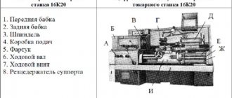
MoscowShpindel.ru
The spindle is usually called the rotating part of a machine, milling or turning. If we consider a lathe, then a workpiece is fixed on a spindle in a chuck, and if we consider a milling machine, then the cutter rotates. Since the sizes of workpieces and cutters can be very different from each other, the spindle speed can vary within very wide limits.
Let us recall that the determining parameter for calculating the spindle rotation speed is the cutting speed, from which it follows that the larger the size of the workpiece for turning and the larger the diameter of the cutter, the lower the required revolutions. Lathes are characterized by speeds ranging from 100 or less to 3000 rpm, which are relatively easy to achieve using the most common asynchronous motors together with a gearbox or frequency converter.
The same applies to conventional vertical milling machines, whose speeds rarely exceed 3000...5000 rpm, since they are mostly designed for power milling with large-diameter cutters.
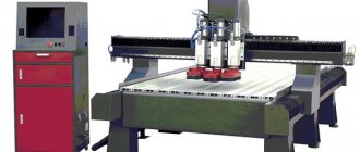
The situation is different for the spindles of modern machining centers and simpler portal milling machines, as well as engraving machines. Recently, high-speed materials processing technology has become widespread due to the availability of affordable high-speed spindles.
The main goal that manufacturers of high-speed spindles and machine tools strive for is to increase the productivity of milling operations, and especially milling with small tools with a diameter of less than 3 mm.
Let's look at the main categories of high-speed spindles that are found on milling machines:
- high-power spindles from 5 kW or more: used mainly on machining centers or large machines, have a speed range of up to 12,000...18,000 rpm and are designed for high-performance processing, including difficult-to-machine materials.
- Medium power spindles 1.5…5 kW: used on medium-sized portal milling machines. Such machines are most often used for cutting various types of plastics, wood and soft metals. The upper speed range of these spindles lies in the range of 18000…24000 rpm.
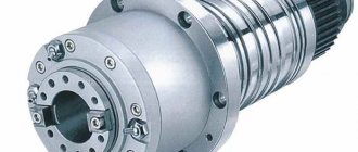
- Low power spindles 0.8 kW or less: used on small milling and engraving machines, as well as on drilling machines for the production of printed circuit boards. The upper speed limit of such spindles reaches 40,000 rpm, and for some models - up to 60,000...70,000 rpm.
Above we looked at spindles built on the basis of an asynchronous three-phase machine and classic bearings. Further increase in rotation speed in such a scheme is difficult due to the presence of mechanical friction and the finite precision of bearing manufacturing. Therefore, the most high-quality spindles use gas-dynamic bearings powered by compressed air. There are also models of spindles built on the basis of an air turbine. Spindles of this design, when used correctly, are extremely reliable and have a long service life.
However, let's return to spindles built on the basis of an asynchronous machine. An asynchronous motor has one significant drawback - the inability to operate at frequencies significantly lower than the nominal one. As the rotation speed decreases, the output torque of the spindle also decreases. Although modern converters can improve the situation, it cannot fundamentally change it. The situation is complicated by the specific use of an asynchronous motor as a spindle, since lower speeds are usually needed to rotate a large tool, which requires just a higher torque.
Practical values of the lower speed limit lie in the range of 20...30% of the maximum declared spindle speed; they strongly depend on the task being performed and the load on the engine. Also note that the stated maximum speeds are not a physical limit. All high-speed spindles can be easily accelerated to 120% of rated speed or even higher, but it should be remembered that bearing life can be dramatically reduced.
Summarizing all of the above, we can say that there is no universal spindle with a wide speed range. The correct size, power and maximum spindle speed can be selected only by clearly defining the task for which it will be used.