Principle of operation
For thread cutting, switching to a special feed shaft is structurally provided.
Its control is located to the left of the worker on the body. The switching dial allows you to select the thread pitch in the metric or inch system. The shape is determined by the configuration of the cutter. Transverse feed regulates the diameter and depth of processing. Modern machines of domestic and foreign production use the same principle. It is considered the most reliable and productive. Rapid feed reduces operation time. In terms of productivity, DIP 500 is not much inferior to modern analogues, with the exception of CNC equipment. During the production of the DIP 500 machine, some modifications took place. Individual batches of equipment may have a bed length different from the standard and a set of additional accessories. The changes also affected some mechanical details. This must be taken into account during operation. In case of repair, replacement only with an original analogue is allowed. It is not recommended to purchase spare parts of dubious manufacture, or made under conditions not intended for the manufacture of elements of the mechanical part of the machine. This will reduce the quality of work and can become a source of danger for the turner. The most critical option is considered to be failure of the frame. It will not be possible to adequately replace or repair it.
Read also: Furniture template jig for drilling holes
Considerable attention is paid to employee safety. Protective covers over moving parts, guardrails
Emergency stop system in case of breakdown or jamming.
Design features of the machine
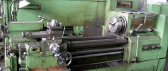
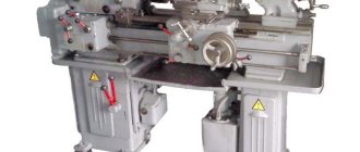
The DIP-500 machine has a conventional design for machines of its class. It is resistant to vibrations and heavy loads. The parts are made of cast iron.
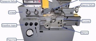
Location of controls
On the front panel there are controls - five handles, above which there is a special plate describing the positions of the handles and their modes.
They control turning the engine on and off, setting the thread pitch and direction, and regulating the rotation speed.
Headstock
It is used to secure the part, give it rotation, and with its help all processing parameters are regulated. The headstock is located to the left of the turner.
Caliper
The caliper moves along the frame between the headstocks and feeds the cutter to the part, determining the speed and pitch of the thread. It can operate in two modes: manual and mechanical.
Apron
Used to move the carriage. Can work both mechanically and manually. There is another trigger mechanism on the apron, which can also turn on the machine and change the rotation of the part.
The front apron cover is removed, inside it there is an overrunning clutch.
Gearbox
The box is located on the headstock and is responsible for controlling the transmission mechanism. With its help, you can turn on the motion shafts and set thread parameters. It provides cutting of metric, inch and modular threads.
Tailstock
Located to the right of the worker. Can be moved around the frame by rotating the handle and gearbox. Tools for carving, making holes are attached to it, and parts are precisely fixed.
Technical characteristics of lathe 165
| Parameter name | DIP-500(1d65) | 165 | 1m65 | 1n65 |
| Main settings | ||||
| Accuracy class according to GOST 8-82 | N | N | N, P | N, P |
| The largest diameter of the workpiece being processed above the bed, mm | 1000 | 1000 | 1000 | 1000 |
| The largest diameter of the workpiece above the support, mm | 620 | 600 | 600 | 650 |
| Maximum workpiece length (RMC), mm | 5000 | 2800, 5000 | 3000, 5000, 8000 | 1000, 3000, 5000 |
| Height of installed cutter, mm | 45 x 45 | 50 | ||
| The largest mass of the workpiece in the centers, kg | 5000 | 5000 | 5000 | |
| Spindle | ||||
| Diameter of through hole in spindle, mm | 100 | 85 | 85 | 128 |
| The largest diameter of the clamped rod, mm | 80 | 80 | 120 | |
| Maximum torque on the spindle, kN/m | 9,5 | |||
| Number of speed steps for direct spindle rotation | 12 | 24 | 24 | 24 |
| Spindle direct rotation frequency, rpm | 4,25..192 | 5…500 | 5…500 | 5…500 |
| Size of the inner cone in the spindle | KM 6 | 100, 1:20 | 100, 1:20 | 100, 1:20 |
| Spindle end according to GOST 12595-72 | 1-15M | 1-15M | 2-15M | |
| Diameter of standard cartridge, mm | 1000 | |||
| Spindle braking | There is | There is | There is | There is |
| Submissions | ||||
| Maximum longitudinal movement of the caliper RMC=3000, mm | 2520 | 2710 | 700, 2700, 4500 | |
| Maximum lateral movement of the caliper, mm | 600 | 600 | 600 | |
| The cost of dividing the dial during longitudinal movement, mm | No | 0,1 | 0,1 | 0,1 |
| Dial division price for transverse movement, mm | 0,05 | 0,05 | 0,05 | 0,05 |
| Maximum longitudinal movement per dial revolution, mm | 10 | 50 | 50 | 50 |
| Maximum lateral movement per dial revolution, mm | 12 | 6 | 6 | 6 |
| Number of longitudinal feed stages | 32 | 32 | 40 | |
| Limits of longitudinal feeds, mm/rev | 0,225..3,15 | 0,20..3,05 | 0,20..3,05 | 0,05..3,05 |
| Transverse feed limits, mm/rev | 0,114..1,6 | 0,07..1,04 | 0,07..1,04 | 0,017..1,04 |
| Maximum longitudinal cutting force Pz, kN | 12 | 12 | 41 | |
| Maximum transverse cutting force Px, kN | 780 | 780 | ||
| Speed of fast movements of the caliper, longitudinal, m/min | No | 2,16 | 3 | 3 |
| Speed of fast movements of the caliper, transverse, m/min | No | 0,735 | 1 | 1 |
| Number of metric threads to be cut | 22 | 44 | ||
| Limits of pitches of cut metric threads, mm | 1..14 | 1…120 | 1…120 | 1…120 |
| Number of inch threads to be cut | 36 | 31 | ||
| Limits of pitches of cut inch threads | 2..28 | 28…¼ | 28…¼ | 28…¼ |
| Number of modular threads to be cut | 13 | 37 | ||
| Limits of pitches of cut modular threads | 0,25..3,5 | 0,5…30 | 1…120 | 0,5…30 |
| Number of cut pitch threads | No | No | No | No |
| Longitudinal switch stops | No | No | ||
| Transverse switching stops | No | No | ||
| Cutting slide (upper slide) | ||||
| Maximum movement of the cutting slide, mm | 240 | 240 | 240 | |
| Price for dividing the tool slide movement dial, mm | 0,05 | 0,05 | 0,05 | 0,05 |
| Number of feed stages | 40 | |||
| Limits of longitudinal feeds, mm/rev | 0,017..1,04 | |||
| Speed of rapid movements, mm/min | 1 | |||
| Maximum rotation angle, degrees | ±90° | |||
| Price of one division of the rotation angle, degrees | 1° | |||
| Tailstock | ||||
| Center in the spindle according to GOST 13214-79 | Morse 6 | Morse 5 | Morse 5 | |
| Maximum movement of the quill, mm | 300 | 300 | 300 | |
| Maximum movement of the quill with the tool installed, mm | 280 | |||
| Quill diameter, mm | 120 | |||
| Maximum movement of the quill in the transverse direction, mm | ±30 | ±15 | ||
| Electrical equipment | ||||
| Number of electric motors on the machine | 1 | 3 | 4 | 3 |
| Main drive electric motor, kW | 17 | 22 | 22 | 22 |
| Electric motor for high speed caliper, kW | No | 1,5 | 1,5 | 1,5 |
| Lubrication pump drive | Built-in | S12-54 | ||
| Cooling pump (pump) | PA-22 | PA-22 | 0,12 | |
| Total power of all electric motors, kW | 23,62 | |||
| Dimensions and weight of the machine | ||||
| Machine dimensions (length width height) RMC=2800.3000, mm | 8000 x 1700 x 1620 | 5825 x 2100 x 1760 | 6140 x 2200 x 1760 | 6140 x 2200 x 1770 |
| Machine weight RMC=3000, kg | 11500 | 12500 | 12800 | 12800 |
Bibliography:
Universal screw-cutting lathe 165. Maintenance and care manual, Ryazan, 1970
Acherkan N.S. Metal-cutting machines, Volume 1, 1965
Batov V.P. Lathes, 1978
Beletsky D.G. Handbook of a universal turner, 1987
Denezhny P.M., Stiskin G.M., Thor I.E. Turning, 1972. (1k62)
Denezhny P.M., Stiskin G.M., Thor I.E. Turning, 1979. (16k20)
Modzelevsky A. A., Muschinkin A. A., Kedrov S. S., Sobol A. M., Zavgorodniy Yu. P., Lathes, 1973
Pikus M.Yu. A mechanic's guide to machine repair, 1987
Skhirtladze A.G., Novikov V.Yu. Technological equipment for machine-building industries, 1980
Tepinkichiev V.K. Metal cutting machines, 1973
Chernov N.N. Metal cutting machines, 1988
Related Links. Additional Information
Home About the company News Articles Price list Contacts Reference information Download passport Interesting video KPO woodworking machines Manufacturers
Purpose and scope of the model
The machine is designed for processing solid substances: metal, plastics, wood, composites. It is an evolutionary product of the DIP line. As production capacity developed, the USSR needed equipment for processing large-sized parts. The previous version of the DIP 400 machine no longer met the new requirements and the need arose to produce the necessary equipment for the needs of the country. One of the principles during creation was the task of developing a universal product to perform all necessary operations. On DIP 500 you can:
- Perform longitudinal cutting operations on the outer and inner surfaces of a rotating body;
- Carry out processing in the transverse direction;
- Make a cone-shaped part;
- Perform operations for the intake of products of complex configuration;
- Drill holes, make their precise development;
- Make metric, inch and modular threads.
When using additional equipment and devices, a number of special operations are performed for special purposes. The potential laid down by the developers has made it possible to realize it for decades, successfully competing with domestic and foreign analogues. High reliability, strength, and accuracy are necessary both for the production of serial products and for the manufacture of unique, one-piece parts.
The machine can use a wide range of processing tools: high-speed steel cutters with brazed carbide plates, drills, countersinks, reamers, thread-cutting devices.
DIP-50 Universal screw-cutting lathe. Purpose, scope
The universal screw-cutting lathe model DIP-50 (1D65) replaced the outdated model of the machine of the same series 165.
The screw-cutting lathe model DIP-50 (1D65) is designed for processing parts of medium and large sizes, in conditions of single and small-scale production. The machine can perform external and internal turning, including turning cones, boring, drilling and cutting threads - metric, modular, inch and pitch).
Operating principle and design features of the machine
The technical characteristics and rigidity of the design of the machine bed, carriage, and spindle allow full use of the capabilities of working at high cutting speeds using cutters made of high-speed steel or equipped with carbide plates when processing parts made of ferrous and non-ferrous metals.
The machine support has a mechanical movement of the upper part, which allows turning long cones. Turning of short tapers is also carried out by moving the upper part of the support.
Changing the feed rates and adjusting the pitch of the thread being cut is carried out by switching the gears of the feed box and adjusting the set of interchangeable gears.
The support has rapid movement in the longitudinal and transverse directions, which is carried out by an individual electric motor.
The machine is designed for processing ferrous and non-ferrous metals at high cutting speeds with cutters made of high-speed steel and hard alloys.
The closed feed box provides cutting of standard threads. Precise threads are cut using replaceable gears, bypassing the feed box.
Changing the spindle speed and caliper feed speed is carried out by switching the gears of the gearbox and feedbox using handles.
The tailstock is moved and the quill is extended manually by rotating the handwheels.
Machine accuracy class N. Machined surface roughness V 6.
The technical characteristics and rigidity of the machines allow full use of the capabilities of high-speed and carbide tools when processing both ferrous and non-ferrous metals.
Type of climatic modification - UHL4 according to GOST 15150-69.
Accuracy class - N according to GOST 8-82E.
Basic data about DIP 300
The screw-cutting lathe machine DIP 300, like the similar model DIP 200, began to be produced by the domestic industry in the 30s of the last century and for several decades was successfully used by almost all machine-building plants. Such machines are most widespread at enterprises producing metal products in small and single batches.
The DIP 300 machine, like its more advanced version 1M63, has high reliability of the spindle and carriage, which is due to the features of its design. Using this machine, you can perform such types of metalworking operations as turning cones, boring, cutting threads of various types (metric, inch, pitch, modular), drilling, turning internal and external surfaces.
In the photo - spindle and gearbox DIP 300
To work on DIP 300, high-speed steel cutters are used, which are characterized by increased strength. These cutters are optimally suited for cutting parts made of both ferrous and non-ferrous metals. Depending on the characteristics of the material being processed, a cutter with soldered carbide plates can be used as a tool.
An important feature of the machines in this series is that the upper slide of their support can be moved, this makes it possible to process long conical parts on such equipment. The caliper itself is driven by a separate electric motor, which makes it possible to move it in the longitudinal and transverse directions at high speed. It should be noted that not all equipment in this series had this capability (in particular, the popular DIP 200 lathe did not have it), which significantly increased the processing time of parts.
Of the main characteristics of this model of screw-cutting lathe, it is worth noting the following:
- The diameter of the installed workpiece can vary depending on the selected processing scheme: when installing above the recess - 900 mm, above the bed - 700 mm, when processing above the support - 350 mm.
- The height of the centers is 315 mm.
- The technical capabilities of this machine allow it to process workpieces whose weight can be up to 3500 kg.
- Spindle characteristics: hole diameter – 105 mm; number of speeds – 22 forward and 11 reverse; rotation speed – 10–1250 rpm (direct), 18–1800 rpm (reverse); drive power to ensure the main movement is 13 kW.
- Limits/number of pitches for threads of various types: metric – 1–224 mm, inch – 28–0.25 threads per inch, modular – 0.25–56 modules, pitch – 112–0.5 diametric pitches.
- The maximum amount of movement of the cutting slide is 220 mm.
- Maximum feed amount: longitudinal – 1260 mm, transverse – 400 mm.
- Technical characteristics of the electric motors with which the machine is equipped: to ensure the main movement - 14/1450 kW/rpm, for fast movements of the support - 1.1/1400 kW/rpm, for coolant supply - 0.12 kW.
- Caliper movement speed: longitudinal – 4.5 m/min, transverse – 1.6 m/min.
- The maximum possible movement of the tailstock quill is 240 mm.
- Model weight – 4.3 tons.
As can be seen from the technical characteristics of this machine, it significantly surpasses many of its analogues in its capabilities and technical equipment, in particular the equipment of the popular DIP 200 model.
Screw-cutting lathe DIP 200
- Lathe Dip 300 in Russia
Technical characteristics and operating principle
Lathe Features:
- normal accuracy of turning parts;
- the presence of additional supports allows you to sharpen long parts;
- the largest size of the workpiece is 100 cm, above the support – 60 cm;
- maximum workpiece weight – 5000 kg;
- the equipment operates using 4 electric motors of different power;
- cooling and lubrication are carried out using two pumps;
- the caliper can move both along and across in accelerated mode;
- Changing gears allows you to precisely adjust the size of thread pitches.
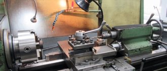
The main working moment is cutting the part while it is rotating in the chuck or centers. The cutting tool can be moved using the auxiliary feed motion.
Cross feed regulates the processing depth. The cutter configuration determines the shape of the part.
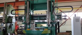
Description
The DIP-500 machine is a turning equipment that is universal; it can be used in various fields of industry for turning operations for manufacturing products. With its help, it is possible to perform the above work with normal accuracy (H) and high productivity. Over the entire period of operation, the machine has proven itself to be highly reliable due to the quality of manufacture and ease of maintenance, and also did not require high attention or special conditions during operation.
The main movement, the cutting movement in this machine, is the rotation of the workpiece, which is processed in the chuck or centers. An auxiliary movement is a feed movement that moves the cutting tool.
https://youtube.com/watch?v=j9aBsj4YRiY
The cutting tools for this type of equipment are turning tools of various types with plates made of hard alloys and high-speed materials, as well as drills, reamers, countersinks, countersinks and various thread-cutting tools and devices.
The passport of this machine contains practical information on technical characteristics and maintenance, thanks to which it had some advantages during operation, namely, it is possible to:
- perform cutting operations at high speeds;
- sharpen long and short cones thanks to the mechanical movement of the caliper;
- achieve a surface roughness index of Ra = 1.6;
- change the spindle shaft speed by switching the gearbox handles;
- adjust the feed amount over a wide range;
- perform cutting of standard threads;
- using handwheels you can extend the quill and move the tailstock;
- using the method of changing gears, adjust the pitch sizes of the cut threads and the movement of the caliper;
- using a separate electric motor of the caliper, move it in the transverse and longitudinal directions in accelerated mode.
Main technical characteristics
Design of DIP-500
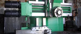
The main structural elements of turning machines are: bed, headstock and tailstock.
Like all lathes of the turning group, the main structural element of the DIP-500 is the bed; it is joined by the headstock, tailstock, support, and then all other structural elements.
The bed is made of solid cast iron, at the top there are slides for longitudinal movement of the caliper, and in the middle there are hatches for cleaning chips and lubricating coolant located at an angle from the workplace.
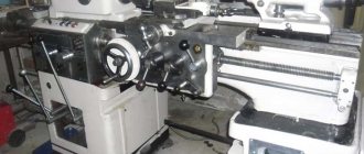
The headstock is located on the left, it is installed using pins and secured with bolts. It contains: a spindle shaft, a gearbox, a feed switchbox, a lubrication system with an oil pump and an electrical control panel. At the bottom there are: an electric circulation pump with a container for lubricating coolant and a main drive mechanism with an electric motor.
The tailstock is located on the right; it moves along guides on the frame using a gearbox, which is driven by the rotation of its handwheel. A rotating shaft is built into the quill, which is also moved by rotating the handwheel.
Specifications
Depending on the design of the center-to-center distance, the screw-cutting lathe 165 has different geometric dimensions and weight. The basic version with RMC-3000 will be considered. Equipment of this class weighs 1280 kg. It is recommended to place machine 165 on a specially prepared rigid base with high vibration resistance. This ensures that the device shows all its impressive capabilities.
Turning parameters and technical characteristics of the installation:
- diameter of the largest mounted workpiece: 1000 mm and 600 mm when fixed above the frame and support, respectively;
- available execution options - 2800, 3000, 5000 RMC;
- maximum dimensions of the cutter section - 45x45 mm;
- weight limit of the processed object - 5000 kg when fixed in the centers;
- the spindle has a hole of 85 mm; a rod up to 80 mm can be clamped in the chuck;
- number of gearbox stages - 24 in the forward direction of rotation;
- number of revolutions on the headstock spindle shaft - from 5 to 500 per minute;
- a fast braking system for the headstock spindle is provided;
- caliper feed rates - maximum 2520 (for a version with a center-to-center indicator of 3000 mm) in the longitudinal direction, 600 in the transverse direction;
- number of gearbox stages - 32;
- to fix the quill, the usual handle is used;
- The system has three electric motors, a 22 kW power motor, a PA-22 type cooling pump, and a 1.5 kW caliper rapid feed drive.
The general dimensions of the model for execution with RMC3000 are (LxWxH) 5825x2100x1760 mm. The device is powered from a 3-phase, 380V AC network. Equipment grounding is mandatory.
Machine characteristics
The technical characteristics of DIP 500 clearly classify it as heavy. Weight, depending on modifications, ranges from 9.85 tons to 20.3 tons. Taking into account the distance between centers (RMC), parts weighing up to 8 and up to 10 tons are processed on a lathe.
The line of models in basic length consists of five versions with dimensions of 4.1, 6.140, 8.180, 9.19, and 11.38 meters. Accordingly, the size of the area where the machine is capable of turning is from 1 to 10 m.
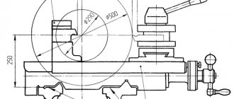
One of the features of the DIP500 series: a hollow spindle with a passage diameter of 100 (in 1967 increased to 128 mm) mm. Such a device, in the presence of additional supports (rests), makes it possible to process parts with a length several times greater than the turning area. This characteristic, along with the possibility of cutting a conical thread with the movement of the caliper, initially provided for the manufacture of equipment (rods) for drilling wells.
In addition to tapered threads, the presence of a feed box allows the DIP-500 to produce metric, modular and inch threads, in a quantity of 22 sizes (respectively); 13 and 36.
Throughout its production history, with unchanged basic characteristics, the DIP 500 screw-cutting lathe has undergone constant improvements. So, in addition to increasing the through passage in the spindle, the rotation speed, previously 192 rpm, increased to 500 rpm. The power of the main drive motor increased from 17 to 22 kW. Together with the gearbox in modern machines, it produces a torque force during processing of up to 9500 Nm (950 kgcm).
All elements of DIP-500 are located on a frame made of special cast iron. Its mass is 2/3 of the weight of the entire lathe and dampens vibrations during deep feeds of the cutter during turning operations.
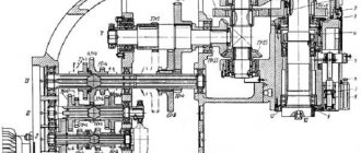
General device
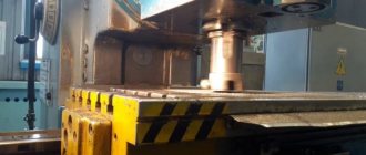
1. The bed has two main prismatic guides with different angles of inclination of the edges. At the front, which accounts for the main force during processing, the cross-sectional area is twice as large. A hole is left in the rear part of the bed to remove chips generated during processing of parts. The support foot of the machine is made solid and is adjacent to the foundation with its entire plane, providing maximum stability.
2. Headstock - with a cast iron body is located to the left of the turner. On top, under a removable cover, are the gearbox gears. In front and below it is the main engine and the V-belt drive mechanism.
3. The technical characteristics of the DIP-500 gearbox provide twelve stages of forward spindle rotation and the same amount of reverse rotation. In addition, accelerate this movement in proportion to 2; 4; 8 and 16 times. Control is carried out using handles on the front panel of the box. Above is a metal plate indicating the position of the handles and the modes that depend on this.
There are five handles: two regulate the rotation speed, one serves to turn on the gear, the rest determine the direction and pitch of thread cutting. There is also a trigger mechanism for the electrical part of the screw-cutting lathe, which ensures stopping and turning on the engine in the forward and reverse directions.
4. The feed box on the headstock is needed to control the rotation of the transmission shafts. Its five handles turn on the apron movement shafts and set the thread parameters.
5. Rotation is transmitted to the feed box by a set of replaceable gears located in another unit - the guitar.
6. On the other side of the DIP-500, to the right of the turner, there is a tailstock. Its task is to center and support long parts.
7. A complex device moves along the frame between the headstocks - a support, which feeds the cutter to the part at different angles with the required speed and pitch. The upper part can be rotated 90° and moved on the carriage either manually or by mechanical drive. Thanks to the latter, DIP-500 cuts not only straight threads, but also tapered threads.
Differences between DIP 300 and 1m63
The machines of the 1m63 family are several modifications of one device, improved in comparison with the DIP-300. In particular, the following indicators have been significantly improved:
- main drive motor power (15 kW versus 13 for DIP-300);
- increased threading speed due to improved mechanics of the feed box and speeds;
- increased landing diameter of the spindle hole;
- modifications of the machine are offered that can process parts weighing up to 3500 kg and length up to 10 meters;
- the use of tool steels and hardened materials significantly increased the service life of the equipment;
- Alloy steel gear boxes ensured wear resistance and thermal stability.
In the design of all machines older than DIP-300, additional protection measures have been implemented, which significantly increased safety when working with equipment and reduced the number of accidents associated with overloads and other emergency situations.
Technical characteristics of the lathe 1N65
| Parameter name | DIP-500(1d65) | 165 | 1m65 | 1n65 |
| Main settings | ||||
| Accuracy class according to GOST 8-82 | N | N | N, P | N, P |
| The largest diameter of the workpiece being processed above the bed, mm | 1000 | 1000 | 1000 | 1000 |
| The largest diameter of the workpiece above the support, mm | 620 | 600 | 600 | 650 |
| Maximum workpiece length (RMC), mm | 5000 | 2800, 5000 | 3000, 5000, 8000 | 1000, 3000, 5000 |
| Height of installed cutter, mm | 45 x 45 | 50 | ||
| The largest mass of the workpiece in the centers, kg | 5000 | 5000 | 5000 | |
| Spindle | ||||
| Diameter of through hole in spindle, mm | 100 | 85 | 85 | 128 |
| The largest diameter of the clamped rod, mm | 80 | 80 | 120 | |
| Maximum torque on the spindle, kN/m | 9,5 | |||
| Number of speed steps for direct spindle rotation | 12 | 24 | 24 | 24 |
| Spindle direct rotation frequency, rpm | 4,25..192 | 5…500 | 5…500 | 5…500 |
| Size of the inner cone in the spindle | KM 6 | 100, 1:20 | 100, 1:20 | 100, 1:20 |
| Spindle end according to GOST 12595-72 | 1-15M | 1-15M | 2-15M | |
| Diameter of standard cartridge, mm | 1000 | |||
| Spindle braking | There is | There is | There is | There is |
| Submissions | ||||
| Maximum longitudinal movement of the caliper RMC=3000, mm | 2520 | 2710 | 700, 2700, 4500 | |
| Maximum lateral movement of the caliper, mm | 600 | 600 | 600 | |
| The cost of dividing the dial during longitudinal movement, mm | No | 0,1 | 0,1 | 0,1 |
| Dial division price for transverse movement, mm | 0,05 | 0,05 | 0,05 | 0,05 |
| Maximum longitudinal movement per dial revolution, mm | 10 | 50 | 50 | 50 |
| Maximum lateral movement per dial revolution, mm | 12 | 6 | 6 | 6 |
| Number of longitudinal feed stages | 32 | 32 | 40 | |
| Limits of longitudinal feeds, mm/rev | 0,225..3,15 | 0,20..3,05 | 0,20..3,05 | 0,05..3,05 |
| Transverse feed limits, mm/rev | 0,114..1,6 | 0,07..1,04 | 0,07..1,04 | 0,017..1,04 |
| Maximum longitudinal cutting force Pz, kN | 12 | 12 | 41 | |
| Maximum transverse cutting force Px, kN | 780 | 780 | ||
| Speed of fast movements of the caliper, longitudinal, m/min | No | 2,16 | 3 | 3 |
| Speed of fast movements of the caliper, transverse, m/min | No | 0,735 | 1 | 1 |
| Number of metric threads to be cut | 22 | 44 | ||
| Limits of pitches of cut metric threads, mm | 1..14 | 1…120 | 1…120 | 1…120 |
| Number of inch threads to be cut | 36 | 31 | ||
| Limits of pitches of cut threads, inch, threads per inch | 2..28 | 28…¼ | 28…¼ | 28…¼ |
| Number of modular threads to be cut | 13 | 37 | ||
| Limits of pitches of cut modular threads, module | 0,25..3,5 | 0,5…30 | 1…120 | 0,5…30 |
| Number of cut pitch threads | No | No | No | No |
| Longitudinal switch stops | No | No | ||
| Transverse switching stops | No | No | ||
| Cutting slide (upper slide) | ||||
| Maximum movement of the cutting slide, mm | 240 | 240 | 240 | |
| Price for dividing the tool slide movement dial, mm | 0,05 | 0,05 | 0,05 | 0,05 |
| Number of feed stages | 40 | |||
| Limits of longitudinal feeds, mm/rev | 0,017..1,04 | |||
| Speed of rapid movements, mm/min | 1 | |||
| Maximum rotation angle, degrees | ±90° | |||
| Price of one division of the rotation angle, degrees | 1° | |||
| Tailstock | ||||
| Center in the spindle according to GOST 13214-79 | Morse 6 | Morse 5 | Morse 5 | |
| Maximum movement of the quill, mm | 300 | 300 | 300 | |
| Maximum movement of the quill with the tool installed, mm | 280 | |||
| Quill diameter, mm | 120 | |||
| Maximum movement of the headstock in the transverse direction, mm | ±30 | ±15 | ||
| Electrical equipment | ||||
| Number of electric motors on the machine | 1 | 3 | 4 | 3 |
| Main drive electric motor, kW | 17 | 22 | 22 | 22 |
| Electric motor for high speed caliper, kW | No | 1,5 | 1,5 | 1,5 |
| Lubrication pump drive | Built-in | S12-54 | ||
| Cooling pump (pump) | PA-22 | PA-22 | 0,12 | |
| Total power of all electric motors, kW | 23,62 | |||
| Dimensions and weight of the machine | ||||
| Machine dimensions (length width height) RMC=2800.3000, mm | 8000 x 1700 x 1620 | 5825 x 2100 x 1760 | 6140 x 2200 x 1760 | 4100..8180 x 2200 x 1770 |
| Machine weight RMC=3000, kg | 11500 | 12500 | 12800 | 9850..15750 |
Bibliography
Screw-cutting lathe 1N65. Operating manual 1N65.00.000 RE, 1991 Screw-cutting lathe 1N65-6, 1N65-8. Operating manual for electrical equipment 1N65-6.00.000 RE1, 2003 Screw-cutting lathe 1N65_5, 1N65-6, 1N65-8. Operating manual for electrical equipment 1N65-6.00.000 RE1, 1995
Acherkan N.S. Metal-cutting machines, Volume 1, 1965
Batov V.P. Lathes, 1978
Beletsky D.G. Handbook of a universal turner, 1987
Denezhny P.M., Stiskin G.M., Thor I.E. Turning, 1972. (1k62)
Denezhny P.M., Stiskin G.M., Thor I.E. Turning, 1979. (16k20)
Modzelevsky A. A., Muschinkin A. A., Kedrov S. S., Sobol A. M., Zavgorodniy Yu. P., Lathes, 1973
Pikus M.Yu. A mechanic's guide to machine repair, 1987
Skhirtladze A.G., Novikov V.Yu. Technological equipment for machine-building industries, 1980
Tepinkichiev V.K. Metal cutting machines, 1973
Chernov N.N. Metal cutting machines, 1988
Related Links. Additional Information
Home About the company News Articles Price list Contacts Reference information Download passport Interesting video KPO woodworking machines Manufacturers
Operating instructions, passport
For proper operation of the machine, you must follow the operating instructions.
- The machine weighs more than 10 tons; together with the workpiece, its weight can increase significantly. Therefore, it is necessary to prepare a separate foundation and a flat, stable platform.
- The device has four electric motors. For them to work, you need to correctly calculate the electrical load. The equipment operates from a three-phase 380 V network.
- During installation, it is necessary to check the reliability of all fasteners. Be sure to monitor the oil level and timely lubrication of mechanisms.
- The bed must be installed strictly horizontally both lengthwise and crosswise. Check the level.
The passport of the DIP-500 machine is similar to its new model 1M65. It can be viewed here.
Description of the design of the main components of the 1M65 screw-cutting lathe
bed
The bed is the basic assembly unit on which all other assembly units and mechanisms of the machine are mounted.
On the top of the frame there are three prismatic guides, of which the front and rear are the base of the carriage, and the middle one is the base of the tailstock.
Inside the frame there are inclined hatches for removing chips and coolant in the direction opposite to the workplace.
Under the left head part of the frame there are niches, in one of which the main drive electric motor is mounted, and in the other - an electric cooling pump with a coolant reservoir. The trough for collecting coolant is made monolithic with the frame body.
On the right side of the frame, on the front wall, a bracket is mounted with supports for the lead screw and lead shaft built into it.
To prevent sagging of the lead screw and the lead shaft, the machine with RMC = 5000 mm has two suspensions.
Headstock
Spindle head of screw-cutting lathe 1m65
Spindle head of screw-cutting lathe 1m65
The front headstock is installed on the left head part of the frame, fixed with pins and secured with bolts.
The following are mounted in the spindle head housing:
- electromagnetic clutch for spindle braking
- spindle unit
- step increase link 8 times
- mechanism for changing the direction of movement of the carriage or threading
- spindle speed adjustment mechanism
- forks for moving gear blocks
- shift knobs and other parts
- Lubrication system
- electrical cabinet
The spindle is mounted on three rolling bearings, of which the front and rear are adjustable.
Tailstock
The rear headstock moves along the frame guides from the manual gearbox by rotating the roller.
A rotating spindle is built into the headstock quill, the front support bearings of which are adjusted using nuts.
The tailstock spindle has a slot for the legs of the tail cutting tool.
Caliper
The support of the cross design has longitudinal movement along with the carriage along the frame guides, and transverse movement along the carriage guides.
Both movements are carried out mechanically using a cross switch and manually by rotating the flywheel and carriage handle.
The cutting slide, carrying a four-position tool holder, moves manually and mechanically along the guides of the rotating part, which can be rotated around its axis at any angle.
The carriage of machines with a digital display device is equipped with a linear displacement transducer, which is connected to the transverse displacement screw using a bellows coupling.
The lateral movement can be counted using the dial and the DRO display.
Apron
The machine apron is of a closed type with a removable front cover. The movement of the caliper group is transmitted by the apron mechanism from the drive shaft or lead screw.
Due to the presence of four electromagnetic clutches in the apron, control of the mechanical movement of the caliper group is concentrated in one handle, and the direction of activation of the handle coincides with the direction of feed.
It is possible to enable rapid movement of the caliper in the direction of tilting the control handle.
Thanks to the overrunning clutch built into the apron, high speed can be activated when the feed is on. The rapid speed electric motor is installed on the apron.
A safety clutch mechanism is mounted in the apron, which prevents the machine from breaking due to overload.
Gearbox
Closed feed box with removable front cover.
The feed box mechanism allows you to get the first row of feeds and all the threads cut on the machine, without having to change the settings of the replacement gears.
To obtain the second row of feeds, replaceable wheels are installed: a = 42, b = c = 126.
Machine equipment
The machine includes a four-jaw non-self-centering chuck with a diameter of 1000 mm.
For processing non-rigid parts, the machine is equipped with two steady rests - movable and fixed.
The movable rest is mounted on the carriage and supports the part directly near the cutter. The breadcrumb coverage diameter is provided in the range from 70 to 250 mm.
The stationary steady rest is installed on the frame guides anywhere and secured with a bolt using a clamp.
It is equipped with crackers and rollers, which are installed depending on the processing conditions.
The diameter of coverage of the workpiece in the stationary steady rest is provided in the range from 70 to 380 mm.
Electrical circuit diagram of the screw-cutting lathe DIP-500
Electrical diagram of the DIP-500 lathe
Electric motors of the screw-cutting lathe DIP-500
The machine is equipped with a three-phase electric motor of normal design with a squirrel-cage rotor. Electric motor type MA202-2/4 with a power of 17 kW, 1500 rpm. Power factor - cosφ = 0.875; the rated current when connecting its windings with a star and when connected to a 380 V network will be 33.3 A, and when connecting the windings with a triangle and connecting to a 220 V network it will be 57.5 A. The electric motor is installed on a skid and connected to the machine by a belt drive .
The coolant is supplied by an electric pump of the ENTS-3 type, mounted on a bracket on the rear side of the machine support carriage. An electric pump consists of an electric motor and a pump mounted on one common shaft. Electric motor with a power of 0.37 kW 2800 rpm, power factor - cosφ = 0.74 kW, efficiency = 0.82, voltage 220/380 V, current 1.9/1.1 A.
Electrical equipment of the screw-cutting lathe DIP-500
1) Magnetic starter . The main motor is controlled by a reversible magnetic starter of the PM-52 type, consisting of two contactors from 3 main contacts and one normally open contact block. The contactors are driven by electromagnets on which a coil is installed for a voltage of 220 or 380 V, depending on the network voltage.
The contactors have a mechanical interlock. To protect the electric motor from overloads, the magnetic starter contains a maximum thermal relay installed on two phases. These relays are equipped with heating elements of type NE105/45 at 220 V and type NE105/38 at 380 V mains voltage.
A thermal relay cannot protect an electric motor from short circuits, since it does not act instantly, but with a certain time delay, which is inversely related to the magnitude of the overload. The electric motor must be protected from short circuits by fuses installed outside the machine by the customer.
2) Push-button stations . Turning on, off and reversing the main engine is done by pressing the corresponding “Forward”, “Stop” or “Back” buttons on the push-button stations.
Two push-button stations of the KU-430 type are installed on the machine. One of them is located at the headstock, and the second is installed on the carriage.
3) Three-pole switches . To control the electric pump, a three-pole packet switch of the PKZ-6/500 type is installed on the apron of the machine carriage in the same box with the push-button station.
The batch switch can be replaced by a three-pole switch of the EL-1 type.
4) Fuses . To protect the electric pump from short circuit currents, type H fuses with normal Edison threads are placed in the same box in which the push-button station and package switch are installed.
5) Wiring on the machine is carried out in gas pipes, as well as in flexible metal hoses. To supply wires, a flexible connection is arranged in the carriage in the form of a bundle of wires stretched into a flexible rubber tube and suspended in a spiral on two steel cables at the back of the machine; Thus, when the carriage moves while working along the machine bed, the spiral either stretches or contracts, providing an unbreakable connection in the electrical circuit.
DIP-300 universal screw-cutting lathe. Purpose and scope
The universal screw-cutting lathe model DIP-300 (according to the classification ENIMS 1d63) is the first Soviet machine with a gearbox and a processing diameter over the bed of 615 mm, like all other DIPs (, , ,), developed and produced at the Moscow machine-tool plant Krasny Proletary from 1930 to 1950s.
The DIP-300 lathe is designed to perform a wide variety of work on centers, collet or jaw chucks for ferrous and non-ferrous metals, including turning cones, as well as for cutting metric, modular, and inch threads.
The DIP-300 (1d63a) lathe is capable of processing relatively large workpieces with a diameter of up to 615 mm and a length of 1500 or 3000 mm.
The front end of the spindle is threaded M120 x 6, the internal Morse taper is 5, the hole in the spindle is 70 mm, the diameter of the processed rod is 68 mm.
The spindle of the DIP-300 (1d63a) machine is mounted on double-row roller bearings at the front and in a tapered roller bearing at the rear. The axial load on the spindle is carried by a thrust ball bearing.
The spindle receives 18 stages of forward and reverse rotation frequencies from a six-shaft gearbox in the headstock of the machine. Setting the desired speed is carried out by three handles on the front wall of the headstock.
Starting, stopping and activation of accelerated reverse motion is carried out by a friction plate clutch. The clutch is controlled by handles on the frame at the headstock and on the apron.
The motion is supplied to the input shaft of the gearbox through a belt drive from an asynchronous electric motor with a power of 10 kW.
The feed box receives movement from the gearbox through the guitar - replaceable gears with an angle. The headstock includes mechanisms that make it possible to change the direction of movement of the caliper and speed up this movement (increase the thread pitch) by 4 and 16 times.
To produce high-precision threads, the lead screw can be connected through the guitar's replacement gears in addition to the feed mechanism.
The caliper receives feeds along the running roller: longitudinal from 0.10 to 1.6 mm and transverse from 0.04 to 0.59 mm per spindle revolution.
The support apron of the DIP-300 (1d63a) lathe is equipped with a falling worm mechanism, which makes it possible to automatically turn on the feed from the lead screw when cutting threads in both directions and at the same time protects the machine from damage in case of overload. Disconnection is carried out with an accuracy of 0.02 mm from the stop on the frame.
History of the screw-cutting lathe DIP-300
In 1930, a decision was made to develop a new standard lathe, abbreviated as TS. Somewhat later it was renamed “ Let’s Catch Up and Overtake
, according to the main slogan of the first five-year plan, where 200 is the height of the centers above the frame.
from the German company VDF
was chosen as a prototype . In April 1932, preparations began for the release of the first batch of DIP-200 machines.
On April 25, 1932, the first Soviet universal screw-cutting lathe with a gearbox, DIP-200, was assembled and tested. By the end of 1932, 25 DIPs were produced.
IN 1934
year, the Moscow machine tool plant “Krasny Proletary” mastered the production of heavy universal screw-cutting lathes, , .
IN 1944
year, the production of these machines was transferred to the Tbilisi Machine Tool Plant, founded in 1944. Kirov and Yeisk Machine Tool Plant.
IN 1956
The Ryazan Machine Tool Plant produced the first industrial batch of machines of the DIP-300 series - model - RMC 1400, 2800.
IN 1968
year, the next generation of the series was launched into production - the model, .
WITH 1973
beginning of serial production of lathes: , , , , .
Tbilisi Machine Tool Plant named after. Kirov produced machines: , 1M63D, 1M63DF101.
IN 1992
year, the serial production of the machine began - the latest model of the DIP-300 series.
Information about the manufacturer of the screw-cutting lathe DIP-500 (1D65)
In 1930, the Moscow Machine Tool Plant decided to develop a new standard lathe, abbreviated as TS. Somewhat later it was renamed DIP-200
–
Let’s catch up and surpass
, according to the main slogan of the first five-year plan, where 200 is the height of the centers above the frame.
from the German company VDF
was chosen as a prototype . In April 1932, preparations began for the release of the first batch of DIP-200 machines.
On April 25, 1932, the first Soviet universal screw-cutting lathe with a gearbox, DIP-200, was assembled and tested. By the end of 1932, 25 DIPs were produced.
In 1934, production of machines DIP-300 (1d63), DIP-400 (1d64), DIP-500 (1d65) was mastered.
In 1944, production of the DIP-500 machine was transferred to the Ryazan machine tool plant RSZ, founded in 1944.
IN 1953
year the lathe
165 into serial production. The main task of the designers was to achieve, if possible, a high level of unification with the model 164 machine. They had to work hard so that before the introduction of the 165 into mass production in 1953, the level of unification with the 164 model would become really high. Only 215 items of parts of this machine were original, and 592 items were unified. In practice, this meant that both machines had the same manufacturing technology, that is, common components, which means they were easier to design, control and, importantly, cheaper to manufacture. The 165s were exported.
Machine tools produced by the Moscow Machine Tool Plant Krasny Proletary im. A.I. Efremova
- 1A62
- universal screw-cutting lathe Ø 400 - 1K62
- universal screw-cutting lathe Ø 400 - 1K620
- universal screw-cutting lathe with variator Ø 400 - 1K282
- eight-spindle vertical lathe Ø 250 - 1K625
- lightweight screw-cutting lathe with an increased line of centers Ø 500 - 16A20F3
– CNC lathe Ø 400 - 16B20P
- high-precision screw-cutting lathe Ø 400 - 16K20
– universal screw-cutting lathe Ø 400 - 16K20M
- mechanized screw-cutting lathe Ø 400 - 16K20P
- high-precision screw-cutting lathe Ø 400 - 16K20F3
– CNC lathe Ø 400 - 16K20F3S32
– CNC lathe Ø 400 - 16K20T1
- lathe with operational control Ø 500 - 16K25
- lightweight screw-cutting lathe with an increased line of centers Ø 500 - 162
— universal screw-cutting lathe Ø 420 - 1730
— semi-automatic multi-cutting lathe Ø 410 - DIP-40 (1D64)
- universal screw-cutting lathe Ø 800 - DIP-50 (1D65)
- universal screw-cutting lathe Ø 1000 - DIP-200
– universal screw-cutting lathe Ø 400 - DIP-300
– universal screw-cutting lathe Ø 630 - DIP-400
– universal screw-cutting lathe Ø 800 - DIP-500
– universal screw-cutting lathe Ø 1000 - MK6046, MK6047, MK6048
- universal screw-cutting lathe Ø 500 - MK6056, MK6057, MK6058
- universal screw-cutting lathe Ø 500 - MK-3002
- table lathe Ø 220