Information about the manufacturer of the vertical milling machine 6Р12
The machine was produced at the Gorky plant. This government agency is known all over the world, since it was from its assembly line that the best types of equipment for industrial purposes came off. The plant was founded in 1931, and a year later it began producing models of equipment designed to work with metal-cutting structures.
Specifically, the P series began to appear in 1972. In the same year, modifications to the 6P12 appeared, followed by the improved 6P12B. A few years later, equipment began to be produced with a more unified scope of use - such machines were part of the M series.
Now the Gorky Plant is no longer engaged in the production of equipment, but at the same time, the devices developed by its employees can be purchased in the Russian Federation. Since 2007, most of the devices have been supplied to the foreign and domestic market by the so-called Machine Park. Engaged in the production of classic and modified versions of the console-milling type.
Vertical milling 6P12 today
The production of boxes and main components of the model in question has been established for several decades at enterprises of the former USSR. However, after the collapse of the Soviet Union, enterprises stopped producing this model. However, the technical characteristics of the feed box and speeds, and the features of the electrical circuit became the basis of new vertical milling machines.
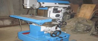
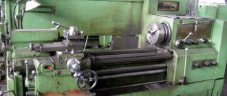
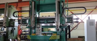
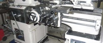
Machine appearance
The cost of 6R12 is 2,100,000 rubles including VAT. In this case, you should study the description more carefully, since the equipment may differ significantly. The electrical circuit, work table, feed and speed box design and other design elements may differ significantly.
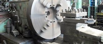
Application area
The 6P12 machine is a milling type, it is used for small-sized elements. Perfectly suitable for cast iron or steel, various non-ferrous metals. At the same time, it is possible to use difficult-to-cut metals - this is the main advantage of the machine.
It is permissible to process not only various vertical and horizontal planes, but also inclined ones with any degree.
You can also use the device to work with rounded or curved surfaces, grooves, corners and frames. There are no restrictions, but instructions must be followed carefully. For example, copiers are used to work with curved surfaces, manual axial displacement of the spindle is used for angular surfaces at 45 degrees, and much more.
Unit design and its features
The unit consists of the following elements:
- electric motor located inside a vertical box;
- a control unit located inside a vertical box, like an electric motor;
- a cast iron frame on which all other mechanisms are mounted;
- milling head equipped with a rotating mechanism;
- cooling unit with electric pump.
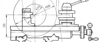
The working table of the unit itself can change its location along both vertical and horizontal axes. The device is characterized by dimensions that exceed the standard dimensions of machine tools.
The 6P12 milling machine table can adjust the axis you need
The device features are described as follows:
- the spindle head has an axis offset, which allows the master to mill products at an angle of 450;
- the presence as an additional element of a copying mechanism intended for milling parts according to a previously created sample;
- The power of the device allows you to process workpieces with cutters containing high-speed steel.
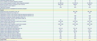
Main technical characteristics
The characteristics are indicated in the technical operation sheet. In particular, these are:
- N accuracy class according to GOST 8-71 and 8-82;
- table dimensions - 1250 by 320 millimeters;
- from the table to the end - up to 450 millimeters;
- vertically of the bed - 350 millimeters;
- The maximum weight of the processed element is up to 250 grams.
The dimensions of the desktop along the X axis do not exceed 800, along the Y axis 250, and along the Z axis 420 millimeters. The speed of the guides is respectively 4, 4 and 1.33 meters per second.
The speed of operation determines the scope of use and efficiency of the machine. Therefore, special attention was paid to the characteristics of the spindle when planning the design. In particular, the parameters are as follows:
- rotation speed - from 40 to 2 thousand revolutions per minute;
- number of speeds - 18;
- hole - 29 millimeters;
- quill - 70 millimeters shift;
- maximum rotation angle is 45 degrees.
Main characteristics
The location of the spindle determines the position of the gearboxes. The main characteristics are:
- The working plane of the table has dimensions of 1250 by 320 mm.
- There is a feed box for moving the workpiece. The passport, which was included with the delivery of the vertical milling 6P12, also indicates the possibility of adjusting the distance between the spindle overhang and the installed workpiece.
- The instruction manual indicates that the spindle can be located at a distance of 30-450 mm from the table. In this case, you should take into account the dimensions of the part.
- The gearbox allows you to adjust the spindle speed in the range from 31.5-1,600 min-1. To rotate the spindle, an electric motor with a power of 11 kW and a table drive of 3 kW are installed. The electrical circuit determines the placement of the motor on the spindle head.
- You can also speed up processing using an electric drive. The electric drive allows you to speed up the movement of the table. The electrical circuit provides for the possibility of moving the workpiece in the vertical direction. The longitudinal and transverse shafts are made of high-strength steel; work can be carried out with manual or automatic feed
- The characteristics of the supporting structure make it possible to support workpieces weighing up to 550 kg. Operation involves relocation to process all surfaces.
- The electrical circuit of the model is quite complex. Looking at the electrical circuit, we note two control units: one is located in front of the table, the second is located on the spindle
Electrical diagram of the machine
- The dimensions of the vertical milling 6P12 are as follows: 2280 by 1965 and 2265 mm.
- Weight is 3,250 kg. The operating instructions provide for the installation of a 6P12 vertical milling machine on a rigid base. The design of such equipment provides for the removal of vibration loads to the base.
At the time of release, the model had a high technical performance indicator. In addition, the electrical circuit and the diagram of the main components determine the high maintainability of the structure.
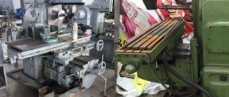
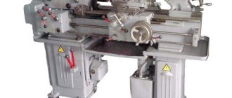
General view of a vertical cantilever milling machine
The machine is a vertical type, that is, this is how the quill spindle is located. It is located inside the rack that moves in this way. We have the necessary devices and tools to process almost any surface. You should initially pay attention to the fact that when working with curved surfaces, a contour along the copiers will be used, which can be performed with the tip of the sensor.
Coolant is supplied through the nozzle; a special pipeline is used. There is a mechanism for axial movement independently - you can produce parts at 45 degrees. Synthetic versions made of very hard materials are also used in the design, since the drives are powerful, the machine has high power ratings. The equipment can be found more often at large production facilities, but their use is not prohibited in single production.
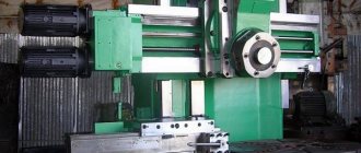
Location of components
The product passport contains information about the location of the component components. They are represented by a frame, gearboxes and speeds. A turning and switching head is installed. There is also control, which is described in detail below in the article. For the convenience of the specialist there is a sled and a table.
Location and list of controls
The location of the control systems is described in the diagram, which also comes with the instructions. Of course, this information should be studied by a specialist, since without this it is dangerous not only to carry out routine inspections and, if necessary, repairs, but also to perform the usual duties associated with the machine. Featured buttons:
- Stop;
- Start;
- Quick stop;
- Pulse;
- Fixation of fungus;
- Changing the position of the head.
There are redundant buttons necessary for operation in emergency mode. The indicators are represented by Speed, Rotation, Table Clamp and Spindle Clamp. There are various handles, in particular:
- actuating longitudinal movements;
- included transverse movements;
- vertical;
- slide clamp;
- switching speeds;
- duplicate main handles.
Warranty and repair
The factory warranty for this equipment is 1 year. The unit itself must undergo regular inspection and diagnostics, especially during prolonged and continuous operation. The most common breakdowns:
- drilling and driving on the table surface;
- the machine does not turn on;
- The network indicator does not work;
- spindle assembly bulkhead;
- collet wear;
- spindle cone wear;
- the center of the spindle is knocked down;
- the spindle does not rotate or rotates slowly;
- sudden interruption of work;
- release of the collet during operation.
During major and restoration repairs, the following work is carried out:
- disassembling the machine with washing and wiping all parts;
- replacement of bearings in electric motors;
- replacing drive belts;
- replacement of worn parts, gears, bearings;
- lubrication of all moving structural elements;
- Overhaul of cooling system pumps.
After repair, the machine must be checked at idle speed, noise, heating and processing accuracy must be checked. When checking the functionality of the machine, a test part is made.
The 6T12 cantilever milling machine refers to equipment that is designed to work with parts made of cast iron, steel, and various alloys. The unit is reliable and rigid, and is a continuation of similar units of the P series.
Used in single and serial production for various industries. The machine is unified and is capable of operating in three modes: automatic, jog and manual. The main advantage for industry is the high productivity and long service life of this equipment.
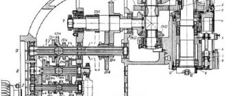
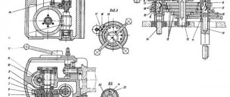
Kinematic diagram
Initially, the movement is supplied from an electric motor through a clutch. From the latter, the spindle begins to move using three blocks with teeth. It is indicated in the product passport that a total of 18 speeds are allowed, which are transmitted from the gearbox to the spindle. There is a motor in the console that determines the transmission of rotation. It moves further into the console through the coupling.
The transmission speed is affected by the clutches near the engine. On the 6P12 machine it is impossible to turn on several speeds at once, thereby ensuring the reliability of the device and the specialists who work with it. The standard element that secures the kinematic system is the frame.