The IZH 250 lathe is still rightly considered one of the most popular models in its class, despite the fact that it has been produced since the early 60s of the last century.
) provides high build quality and durability. Modified versions have been developed and produced on the basis of this model. Knowledge of its features and technical capabilities will help you correctly evaluate the advantages of the machine.
What tasks does the unit solve?
The turning, or more precisely, screw-cutting lathe, IZH-250 belongs to multifunctional equipment and is designed to mechanize the work of a turner when working with parts in centers, a collet or a chuck.
It is widely used in the formation of various threaded structures (metric, inch, modular). This equipment is installed both in the workshops of large factories and in the workshops of small enterprises during mass production, production of small batches of products or repair of various equipment.
A sufficient degree of accuracy when working with small-sized parts allows the IZH-250 to be used in instrument making, mechanical engineering and tool manufacturing.
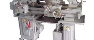
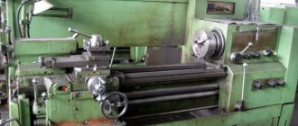
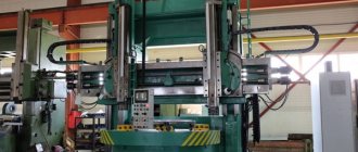
General view of the screw-cutting lathe 250ITVM
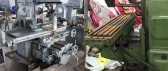
Photo of a 250itvm screw-cutting lathe
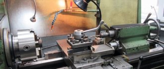
Photo of a 250itvm screw-cutting lathe
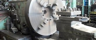
Photo of the headstock of a 250itvm screw-cutting lathe
Photo of the headstock of a 250itvm screw-cutting lathe
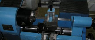
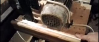
Spindle of screw-cutting lathe 250itvm
Support for screw-cutting lathe 250itvm
Main technical characteristics
The basic model of a lathe has the following main technical parameters:
- the maximum diameter of the part when installed above the frame (category “Disk”) is 25 cm;
- the maximum diameter of the part installed above the caliper (category “Shaft”) is 12.5 cm;
- distance between attachment points – 50 cm;
- center height – 150 mm;
- standard electric motor power – 2400 and 3000 W;
- total weight of the equipment is 1500 kg.
Processing accuracy class B is ensured according to GOST 8–82.
Machine device
Electrical equipment of lathe IZH250
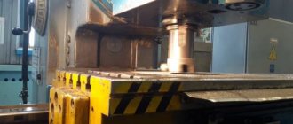
The frame is made by casting, it has reinforcements in the form of a U-shaped rib and is installed on a durable stand. The material for the frame is chromium-nickel cast iron. The bed is equipped with 4 guides (two are prismatic, the rest are flat). The latter are subjected to high-frequency surface hardening and grinding. Inside the cabinet there is an electric drive that rotates the gearbox, an automatic lubrication station and a coolant supply system (cutting fluid).
In accordance with the kinematic diagram of the machine, the gearbox plays the role of a gearbox driven by an electric motor mounted on the flange. To fix the gearbox in the cabinet there is an intermediate bracket.
The gearbox has a speed pre-selection device. This procedure is carried out without stopping the machine. The handle turns the flywheel connected to two disks, with the help of which the number of revolutions is selected. The discs form a set of pin holes with levers that flip the gear blocks. To stop the rotation of the gear wheels (up to a speed of less than 100 rpm), this handle is slightly pulled towards itself (a feeling of resistance), and a pause is maintained. Then, with an effort in the same direction (towards you until failure), the gear is engaged. At low speeds, this procedure is done with one movement of the handle.
To make it easier to transfer or change the drive belt (without having to disassemble the entire assembly), its pulley is shifted to the left half of the tailstock housing. The base for mounting the latter is a pin installed at the bottom of the spindle. This element controls the spindle assembly itself in case of heating of the latter and facilitates control of the position of its rotation axis. The rotational torque to the machine spindle comes directly from the pulley or through the selection gears. In front of the headstock body there is a shift knob between the gear coupling and the gearbox. The block will not allow you to turn them on at the same time. To avoid breaking the gears, do not move the handle until the spindle assembly comes to a complete stop. The design of the headstock includes a link that increases the thread pitch.
Using the feed box, thread cutting processes are adjusted or feeds are switched during turning. The size of all transverse feeds is half the size of similar longitudinal feeds. The gearbox rotates the input shaft of the specified box through a replaceable set of gears (thread) or a belt (all other operations). Feed switching at spindle speeds of less than 100 rpm is allowed on the fly. If the speed is higher, then only by coasting (reducing the speed) of the spindle by briefly turning off the rotation on the machine using the provided handle.
The guitar is mounted on the left end surface of the headstock. Due to the presence of blocking, it is impossible to engage the gear drive together with the belt drive.
You can lock the tailstock by turning its handle. The clamping force can be adjusted using nuts. An additional screw will contribute to the reliability of the clamp. Grooving short cones on the machine is made easier by the fact that it is possible to move the tailstock body relative to the axis of the machine centers. The displacement is made by no more than + - (10 mm) with a special screw. To control the horizontal position of the axis of the machine centers (relative to the bed guides), the corresponding bosses are aligned on the body and the tailstock tray. The quill is fixed using its handle.
The main functions of the apron include: implementation of the feed movement (longitudinal or transverse) for the caliper through the running shaft; cutting threaded surfaces - from the lead screw. Therefore, the apron is equipped with 4 couplings, which include direct or reverse feeds. These models of machines do not have accelerated cutting of the cutter.
During operation of the machine, the cross-shaped support moves along the workpiece using bed guides, and across it along similar elements of the carriage. Longitudinal movements are carried out manually or mechanically. On top of the caliper there is a main tool holder with four places for the tools. On request, an additional rear single tool holder for the transverse carriage can be supplied.
To cover the cutting zone from flying chips, a protective fence with an opening made of durable transparent polymer was installed. It is mounted using a height-adjustable stand. When cutting workpieces made of brittle material, an additional protective screen is used, which is attached to the main one on the right.
Design features of the structure
Design solutions provide the following key features of the machine:
- increased gear range and spindle speed;
- automation of lead screw lubrication during thread cutting;
- location of the machine stopping mechanism in the apron, providing a rigid stop;
- securing the cutting tool without gaps;
- preselective spindle rotation control;
- universal gearbox design;
- special spindle design that simplifies the installation and replacement of drive belts;
- high-strength frame made of chromium-nickel cast iron.
Feed control is carried out by one lever according to the mnemonic principle, while the cutting head moves on the support in accordance with the movement of the handle.
General form
Like any screw-cutting lathe, it consists of the following main components and parts: caliper, headstocks (front and rear), gearbox, supporting frame, spindle, gear guitar, running shaft, apron, feed control box, equipment stand, electrical equipment. A screw-cutting lathe (TVS) is distinguished by the presence of a lead screw for cutting threads.
Workspace dimensions
An important characteristic of a fuel assembly is the dimensions of the working space, which determine the maximum dimensions of the workpiece being processed.
The main criteria are the distance between the fixing points of the part (500 mm) and the maximum diameter of the workpiece (250 mm). In addition, it is important to take into account the dimensions of the support and its mounting, which allows you to determine the maximum dimensions of the cutting tool.
List and location of controls
The IZH-250 TVS has a closed apron, with the help of which the caliper moves in various directions manually or automatically. A lead screw is used to cut threads.
The feed is controlled by a handle. The locking device prevents the simultaneous activation of different feed directions, the roller and the screw.
The machine control system includes the following elements:
- selection handwheel and spindle speed switching handle;
- handles for setting feeds and thread pitch;
- bit and bust handle;
- manual longitudinal and transverse feed steering wheel;
- handle for fastening the tool holder and the lead screw nut; upper skid steering wheel;
- handles for securing the quill and tailstock;
- reverse feed handle;
- quill movement wheel;
- vernier flywheel;
- start and stop handle;
- safety device adjustment screw;
- dialing console;
- power switch;
- switches for cooling, oil pump, display unit, lighting, emergency stop;
- digital display and buttons for calling up information on it and resetting it.
Spindle
In the IZH-250 TVS, the spindle is mounted on bronze plain bearings, with the possibility of adjustment. The rotation speed can vary within wide limits.
Its 22-step adjustment is provided, with 12 steps installed using a V-belt, and 10 steps using a box in the headstock. Speed change limits – from 15 to 2000 rpm.
The end of the spindle has an M68x6 thread, which allows the installation of a standard chuck (diameter 200 mm) through an intermediate threaded flange. The spindle has a hole with a diameter of 33 mm for a rod measuring 30 mm. Instrument cone type – Morse 5.
Feeds and threads
The caliper is fed manually or mechanically in the longitudinal and transverse directions. Manual movement is carried out using the appropriate steering wheel. Mechanical feed parameters:
- feed range in the longitudinal direction – 0.06-2.18 mm/rev;
- cross feed range – 0.01-1.07 mm/rev.
Thread cutting occurs when the lead screw is turned on. Using the handles, its parameters are set. The machine is capable of providing the following pitch ranges for different types of threads:
- metric – 0.1-6.2 mm;
- modular – 0.2-6.5 modules;
- inch - 3.5-26 threads per inch.
Important!
Simultaneous activation of the feed of the caliper and the lead screw eliminates blocking.
Headstock
In the headstock of the TVS IZH-250 there are the following elements: a take-up pulley, a spindle, a bust (1:8) and a threaded pitch link.
It provides additional spindle rotation control through the gear guitar.
Friction clutch
The friction clutch of the machine is made in the form of a console and is designed to transmit torque to the working units. In IZH-250 it has a square shape and contains 8 main elements.
Gearbox brake
The brake, which is connected to the friction clutch, allows you to accelerate the reduction in rotation speed and make a complete stop. The IZH-250 FA is equipped with a high-quality braking device that ensures high reliability and safety.
Gearbox
The structure of the machine feed box requires careful study before working on the equipment. It sets the speed of movement of the caliper and lead screw.
When carrying out turning operations, the torque from the spindle is transmitted to the box shaft by a V-belt, and when cutting threads - through a gear guitar.
Control is carried out by 4 handles. These include slide or lead screw movement, as well as feed and thread parameters.
At low rotation speeds, switching is allowed on the go. There are thread and feed tables for proper installation.
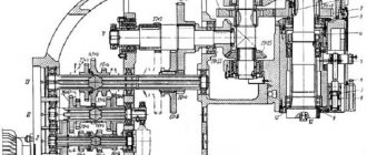
Kinematic scheme
The kinematics of the IZH-250 fuel assembly units is quite complex, and its diagram is intended for specialists. The main drive is carried out by an electric motor through a gearbox, providing 12 stages of rotation speed adjustment.
Further, the rotational motion is transmitted through a belt drive. The take-up pulley is located in the headstock, where the overhaul is located for installing additional speed stages.
A simplified diagram can be illustrated as follows. The gearbox in the form of a 4-axle gearbox is located in the left cabinet of the machine.
From it, a V-belt transmits rotation to the spindle. A friction clutch with a brake is provided on the drive shaft of the gearbox.
From the spindle, the movement passes into the feed box, from where, through the output shaft, the torque is transmitted to the support roller or lead screw for thread cutting. In the caliper apron, rotation is converted into translational movement.
Electrical circuit diagram
The electrical circuit diagram of the equipment is shown below. The following electrical equipment is installed in the IZH-250 FA:
- Asynchronous, three-phase electric motor FT42-4/2 with power switching of 2.6 and 3 kW and speeds of 1420 and 2800 rpm to provide the main drive.
- Asynchronous electric motor with a squirrel-cage rotor with a power of 0.2 kW and a speed of 1400 rpm for the oil pump.
- 0.12 kW, 2800 rpm motor for cooling pump.
- Starter PMI-1.
- Reversing starter for the main electric motor – PMI-1R.
- Thermal relay RT-1 for protecting electric motors.
- Circuit breakers 63–100 A.
The electrical circuit provides starting and shutting down of electric motors, speed control, and protection from unforeseen circumstances.
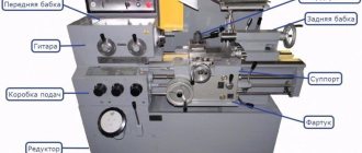
Location of controls for screw-cutting lathe 250ITVM
Location of controls for a 250itvm lathe
List of controls for the 250ITVM machine
- Spindle speed selection handwheel
- Spindle speed switch
- Handles for selecting feed rates and thread pitch
- Handles for selecting feed rates and thread pitch
- Handles for selecting feed rates and thread pitch
- Shift knob
- Switching handle for bit and pitch increase link
- Cooling pump switch
- Input switch
- Main switch locking lock
- Digital display for machine 250ITVM F1
- Lubrication station switch
- Button for general stop and emergency shutdown of the machine
- Manual longitudinal feed handwheel
- Manual cross feed handle
- Tool holder fastening handle
- Lead screw nut on/off handle
- Flywheel for moving the upper slide
- Light switch
- Quill clamp handle
- Handle for securing the tailstock on the machine
- Quill movement flywheel
- Nut for securing the tailstock to the bed
- Feed reverse handle
- Start and stop handle
- Safety mechanism adjustment screw
Nuances of operation and passport
The machine should be operated in strict accordance with the equipment instructions. The adjustment must be carried out by a specialist.
Features of operation:
- Electrical equipment operates from a three-phase electrical network with a voltage of 380 V.
- Connection to the network is made through a batch and circuit breaker.
- In a number of models in the series under consideration, the speed is not adjusted by the gearbox. To do this, the power of the supplied electrical signal changes. In this case, electric motors of increased power (up to 5.5 kW) are installed.
The feed box provides wide possibilities for varying the feed and thread parameters. To use them correctly, you must use standard lever installation tables. The accuracy of the lateral movements of the tool is increased by the vernier (the accuracy increases to 0.005 mm/rev).
You can download the machine passport for free from the link - Passport of the IZH-250 lathe
Features and capabilities
Analyzing the drawings of the 250ITVM, you can notice a lot of docking points for additional modules. The passport of the improved model is characterized by superior technical parameters, which allows for work with maximum loads. The accuracy of this model is ensured by a special digital indicator, thanks to which there is no need to spend a lot of time for manual measurement of workpiece parameters, and the need for trial runs is also eliminated.
Machine appearance
The Izhevsk plant has provided the ability to connect highly efficient modules even to basic standard equipment; this feature is used during modernization.
The 250ITVM installation is equipped with a function for fixing the head of the cutting tool without clearance. By carving using this technology, maximum rigidity, stability and accuracy are maintained throughout the operation. During thread cutting, the main lead screw is automatically lubricated. Thanks to the unique design of the spindle module, instantaneous change of drive belts is possible, and disassembly of the hub unit is not required.
How used is the model today?
Serial production of the IZH-250 fuel assembly began in 1964, but even today the machine has not lost its relevance. The base model has undergone virtually no changes.
Modern technologies have made it possible to improve the quality of equipment assembly, which has increased the processing accuracy and durability of the equipment. At the same time, the distinctive feature of the machine is its low cost, versatility, ease of setup and operation.
Description of the electrical equipment of the EMU-200 machine
Power supply data:
- Mains voltage 380 V, 50 Hz
- Maximum operating current 5 A
- Maximum starting current 20 A
- Rated current of the main fuse / refractory / 10 A
Description of electrical equipment operation
To make it easier to see the connections in Fig. Figure 5 shows a schematic diagram of the electrical equipment of the machine. The network is connected to the RST terminals of the terminal block. The machine is protected from short circuits by fuses. The pump motor and transformer are also protected by fuses.
The on position of the input switch is indicated by a red signal lamp. The auxiliary circuit of the contactor is designed for 24 V, which also powers the signal lamp. This voltage is generated by a 100 VA transformer TM. The transformer is protected from overload by two fuses. It is allowed to use an incandescent lamp up to 60 W, 24 V for lighting.
Starting the drive motor, as well as reversing, is carried out using the reversing switch FJ. The PSZ switch is used to start the coolant pumps.
If the voltage disappears, the motors are started again only if the FJ switch and the PSZ switch have been previously set to the “O” position.
Work, machine and service organs
When the electric motor is turned on, the spindle also starts. The spindle is stopped and reversed electrically by stopping and reversing the electric motor.
The permissible number of spindle reverses is as follows: at 90-130 rpm. spindle 600 reverses per hour, at 140-380 rpm. spindle – 400 reverses per hour.
Spindle speed – Two cases are possible;
- a) Speed 90-480 rpm. In this case, the handle for switching the spindle drive through overdrive or direct drive /18. rice. 8/ turn right. After this, by moving the reversing handle 36 to the left or right, turn on the forward or reverse direction of rotation of the engine and with it the spindle. Only after this is it possible to turn the speed adjustment knob 34 until the corresponding speed value on the spindle speed dial 33 aligns with the pointer,
- b) Required speed 630-315 rpm.
Move the handle for switching the spindle drive through overdrive or direct drive /18/ to the left, and then, after starting the engine, adjust the required number of revolutions.
The right position of the handle corresponds to lower spindle speeds /33/ on the dial, and the left position of the handle corresponds to higher speeds.
The handle for switching the spindle drive through overdrive or direct drive is allowed to be switched only when the spindle is stationary, and the handle for adjusting the speed of rotation - only when the spindle is rotating.
Reversing the spindle is carried out by reversing the motor /switch 36/.
The machine can be stopped so that the switch handle 36 is moved to the neutral position
Differences between modifications
Engineering thought does not stand still, and modified machines have been mass-produced, which have absorbed the best features of the IZH-250, but have also acquired specific features.
IZH 250 ITVM 01 and 03
The machine is distinguished by its increased dimensions of the working space. The center-to-center distance is 700 mm. The diameter of “Shaft” type blanks has been increased to 170 mm.
IZH 250 ITVMF1
The model is equipped with a display with modern indication.
IZH 250 ITPM
Priority in the machine is given to turning work. Processing class P according to GOST 8–82 is provided. Weight – 1200 kg.
Among the latest modifications, we can highlight the IZH-250 SCI model, equipped with an accurate indication (up to 100 microns in diameter). The machine provides linear compensation for tool wear.
The IZH-250 lathe has been popular for more than 50 years. It is distinguished by fairly high accuracy of parts processing and increased reliability.
Modern modifications are quite competitive with other machines of more recent developments. This equipment can be recommended to both large businessmen and individual entrepreneurs for setting up small production.
Equipment technical parameters
The lathe has a number of design features:
- equipped with a special mechanism that allows turning and at the same time protecting working units from overloads;
- During operation, the lead screw is automatically lubricated;
- spindle and feed speeds can vary over a wide range;
- to replace belts, the spindle assembly does not need to be disassembled;
- the cutting head is very precisely and firmly fixed, which makes it possible to achieve high precision thread performance;
- changing thread types is done due to the versatility of the gearbox, and not by changing gears.
The machine body is made of a durable type of cast iron, and the guides are ground and hardened using high-frequency currents.
The feed control on the presented turning unit is carried out using a handle and is carried out according to the principle when its movement coincides with the movement of the feed element.
Machine design and modifications
Appearance
The functional purpose of lathes model IZH-250 is wide. With their help, you can process workpieces using the rotation method. In this case, the part is mounted in a collet, centers or chuck. Additionally, it is possible to form threads of various types.
The design of the equipment is standard, but has a number of features. These include a wide range of gear shifts and cutting tool feeds, the ability to pre-set an operating mode that will turn on in a certain period of time. For ease of control, a mnemonic mechanism is provided. The lead screw is automatically lubricated during thread formation.
In addition, there are several types of machine modernization, which differ in technical and operational qualities, as well as equipment.
- IZH-250ITVF1. Equipped with a digital display unit. With its help, you can significantly increase labor productivity, since the worker does not waste time measuring the actual dimensions of the workpiece;
- IZH-250ITP. Designed for rough processing. This model is produced by special order only.
All types of equipment have a twelve-speed gearbox. High-reliability V-belts are used for drive. The gear block switches when the disks, which have holes for the locking pins, are displaced.
Increasing the accuracy of thread formation is carried out using a vernier mechanism installed on the IZH-250 machine. Additionally, a diagram for connecting the guitar to the lead screw is provided. It allows you to improve processing accuracy.
The machines of this series have gained the greatest popularity for completing production lines specializing in instrument making. This is due to the possibility of individual configuration and changing some machine parameters when ordering from the manufacturing plant.
Dimensions of the working space of the IZH-250 lathe
Dimensions of the working space of the IZH-250 lathe
The screw-cutting lathe 250ITVM.01 is a unit for performing technological operations. It is used for turning, one of the main methods for processing metals by cutting, and mainly in industrial settings, within production enterprises of various sizes.
The IZH250ITVM model lathe, due to its relatively small overall dimensions, occupies little area of the production site. Its power consumption is not high. When processed, the unit provides dimensional accuracy of class “B” (high) parts. This equipment is made with high quality and can be used for a long time. It is preferable to use it:
- For single production of small-sized products in instrument-making or tool production.
- For semi-finishing or finishing.
In order to prevent subsequent abnormal or emergency situations, purchase machines after maintenance/refurbishment.
Purpose and description of the unit
The screw-cutting lathe 250ITVM.01 is distinguished by a decent set of functions, as well as a reasonable price. This unit easily turns small metal workpieces. To maintain its high processing accuracy longer, do not use it for large series of parts and, in particular, for their pre-processing. For such processes, the line includes a 250 ITPM unit, which is produced to order.
The specified equipment was produced by the IzhmashStanko machine tool plant (Izhevsk). Units, components and spare parts for them are available for sale in full. Moreover, their cost is reasonable.
The entire series of machines we are considering was developed on the basis of the structurally and technically successful design of the IZH1I611P unit. They perform various types of turning operations with fixation of the part with a chuck, collet clamp or rotating centers, and cut inch, metric and modular threads.
The main drive is made by an electric motor operating on a V-belt drive (single and poly V-belt) or a gear reducer (12-speed).
The following is mounted in the headstock housing:
- Spindle assembly combined with input pulley.
- Sets of gears (two) - overkill (with a gear ratio of 1:
 and a link that increases the thread pitches.
The productivity of work on the machine can be increased by eliminating the test run with subsequent measurements of parts. This innovation is implemented in the IZH250ITVMF1 lathe. For this purpose, it has a digital display device (DRO). It greatly simplifies the work of a specialist in calculating the cutting depth, the corresponding number of dial revolutions, and recording them on the screen. The DRO helps ensure the machine has high processing accuracy due to:
- Reflections of size values (in mm, inches) with a resolution of 0.1 - 100 microns.
- Taking into account compensation amendments that take into account the wear of the rubbing pairs of the machine unit and the edge of the cutting tool.
Precise counting for cross feed (up to 0.005 mm/rev) is carried out by a vernier-type mechanism. This is a flywheel with a vernier scale. The feed box is able to change the speed of the cutter during threading, turning and other operations. And it does this within a fairly wide range. Threads are cut with high precision provided that the lead screw is directly connected to the guitar (without the participation of a feed box).