If one end of a long homogeneous rod is fixed and a twisting moment of force M
, then this end will turn at an angle , and, according to Hooke’s law:
. (1)
The constant value is called the torsional modulus. The torsional modulus is related to the shear modulus of the material of the rod G
ratio:
, (2)
where r
is the radius, and
L
is the length of the rod.
Note that the simple linear relationship between the values of M
and given by formula (1) occurs only for relatively small values
of M. In the general case, the dependence can be not only nonlinear, but also ambiguous.
I. _ Determination of the torsional modulus of a rod using the static method
Accessories: test rod, reading tube with scale, tape measure, micrometer, set of weights.
The experimental setup is shown in Fig. 1. upper end of vertical rod C
is rigidly fixed to the rack, and the lower one is connected to
disk
D. The moment M
, twisting the rod, is created by two threads wound on the disk and thrown through blocks
B
, to the ends of which identical loads
G
.
The disk is equipped with a
mirror Z. To determine the angle of twist of the rod, you need to point the telescope at the mirror and ensure that the reflection of the scale mounted on the same tripod as the telescope is visible through it. By observing through the pipe the displacement of the visible portion of the scale when the rod is twisted, one can determine the angle of twist.
Fig.1. Installation diagram for
definition of torsional modulus
Measurements
- Position the telescope so that the reflection of the scale in the mirror can be clearly seen through it Z
.
- Increasing the load on the threads N
, remove the dependence. Do the experiment in reverse order, gradually reducing the amount of torque. Perform the entire set of measurements at least three times.
- Display the results of the experiment graphically in coordinates. Using these graphs, determine the value of ƒ and estimate the error allowed.
- Using formula (2), calculate the shear modulus G
. Check the value obtained in this way with the table one.
II . Determination of shear modulus using torsional vibrations
Accessories: wire from the material being tested, weights, stopwatch, micrometer, tape measure, scale ruler.
The experimental setup consists of a long vertically hanging wire, to the lower end of which is attached a horizontal metal rod with two symmetrically located weights. Their position on the rod can be fixed.
The upper end of the wire is clamped into a collet and, using a special device, together with the collet can be rotated around a vertical axis. In this way, torsional vibrations can be excited in the system. Let us write down the equation of motion for this case:
. (3)
Here M
– moment of forces, which owes its origin to elastic deformations,
J
– moment of inertia of the rod with loads, – angle of rotation of the rod.
If the amplitude of oscillations is small, then to determine the moment of force M
you can use Hooke's law in the form (1).
The moment M
in this case is caused by the deformation of the wire and tends to reduce rather than increase the angle . In formula (1) it is therefore necessary to change the sign. After substitution (1), formula (3) takes the form:
. (4)
; from here:
, (5)
where the amplitude and phase are determined by the initial conditions. Thus, is the angular frequency of torsional vibrations of the rod, period T
which is equal to:
. (6)
It should be noted that the last formula was obtained for undamped oscillations, while in fact the oscillations of the rod are damped. If, however, the attenuation is small, i.e. the change in the amplitude of oscillations over a period is much less than the amplitude itself, then formula (6) can be used. The criterion for its applicability is the inequality:
P
> > 1, (7)
where n
– the number of complete oscillations, after which the amplitude decreases by 2-3 times.
Note that period T
, as can be seen from formula (6), does not depend on the amplitude . However, at large amplitudes, Hooke's law is violated, and such a dependence can appear. Thus, the second condition for the applicability of the described method is compliance with the equality:
T = const
. (8)
Torsion
Torsion is one of the types of body deformation. Occurs when a load is applied to a body in the form of a pair of forces (moment) in its transverse plane. In this case, only one internal force factor arises in the cross sections of the body - torque. Tension-compression springs and shafts work for torsion. During torsional deformation, the displacement of each point of the body is perpendicular to its distance from the axis of the applied forces and is proportional to this distance.
Torsional deformation can be observed if a rod, one end of which is fixed, is acted upon by a pair of forces lying in a plane perpendicular to the axis of the rod. During torsion, the individual layers of the body remain parallel, but rotate relative to each other at a certain angle. Torsional deformation is uneven shear. Torsional deformations occur when screwing nuts and when operating machine shafts.
Example of torsional deformation of a cylindrical rod
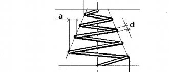
If a wire or rod, fixed at one end, is twisted, applying a pair of forces F to the other end with a moment equal to M, then the rod (wire) undergoes torsional deformation, in which one of its bases rotates relative to the other, fixed, at a certain angle φ – torsion angle (Fig. 1; 2).
Rice. 1.
The ratio of the twist angle φ to the length is called the relative twist angle
Hooke's law for small torsional deformations is expressed by the formula
M = Gcr.j
where Gcr is the torsion modulus.
Torsional modulus, in addition to the material, also depends on the shape and size of the body.
Imagine there is a cylinder (or wire) in front of you. If you begin to rotate its (her) upper end along the axis, securing the lower end, then when you rotate the upper face by one radian, you apply a torque exactly equal to the torsion modulus (Fig. 1; 2). This is its definition.
The torsion modulus Gcr shows what moment of force must be applied to twist the wire through an angle of 1 rad.
Rice. 2.
Torsional deformation is a special case of shear deformation.
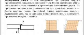
Shift
A shear is such a deformation of a solid body in which all its flat layers, parallel to a certain shear plane, without bending or changing in size, are displaced parallel to each other (Fig. 3).
Rice. 3.
Shear deformation occurs under the action of forces applied to two opposite faces of the body as shown in Figure 3; 4. These forces cause displacement of layers of the body parallel to the direction of the forces. The distance between layers does not change. Any rectangular parallelepiped, mentally identified in the body, turns into an inclined one.
Rice. 4.
A measure of shear deformation is the shear angle γ—the angle of inclination of the vertical faces (Fig. 5).
Rice. 5.
The shear occurs under the action of a tangential force F applied to the face BC parallel to the shear plane. The edge AD, parallel to BC, is fixed motionless.
Since the angle is small, the formula can be written as:
where CC1 = DX is the absolute shift, γ is the shift angle, also called relative shift, expressed in radians.
According to Hooke’s law, the relative shift γ is proportional to the shear stress τ = F/S, where S is the surface area of the BC face, i.e.
τ = F / S = Gg
where G is the shear modulus.
Hooke's law for small shear strain is expressed by the formula:
The coefficient G, which depends on the material of the body, is called the shear modulus and characterizes the elastic properties of the body under shear deformation. For example, for a steel sample G = 76 GPa.
The shear modulus is equal to the shear stress that would arise in the sample with a relative shear equal to 1 (provided that Hooke's law is satisfied).
Shear deformation is experienced, for example, by rivets and bolts connecting metal structures. Shear at large angles leads to destruction of the body - shearing. The cut occurs when using scissors, saws, etc.
Please note the fundamental difference between the torsional modulus and the shear modulus, which depends only on the material. The torsional modulus depends not only on the material, but also on the diameter and length of the cylinder.
Measurements
- First of all, set the amplitude range in which condition (8) is satisfied. To do this, strengthen the weights at a certain distance from the wire and excite torsional vibrations in the system. By measuring the time of several (at least 10) complete oscillations, find the period T1
.
T 2
in the same way .
if T 1 = T 2
, then for measurements you can choose any amplitude no greater than the first.
If it turns out that , then the amplitude must be reduced to such a value, starting from which for all < the equality T 1 = T 2
. - Check the validity of inequality (7).
- By placing the weights so that their centers of mass are at a certain distance L1
from the system axis, measure the period as described above.
If J
is the moment of inertia without loads, and
J 1
is the moment of inertia of loads, then, obviously:
. (9)
By changing the distance of the loads to the value L 2
, similarly we get:
. (10)
From (9) and (10) it follows:
,
where 2t
– the mass of two loads. The mass of one load is 550 g.
Determination of the value of ƒ
carry out for several (at least 5) pairs of values
L 1
and
L 2
.
the value of ƒ
can also be found from the slope of the line in the graph, along the axes of which
L 2
and
T 2
. elaboration of this issue is left to the reader.
- Knowing ƒ
, find the value of the shear modulus
G
using formula (2) and estimate the error allowed.
Examples
- Let M
be a free module over a ring
R
, the definition immediately implies that
M
is a torsion-free module. In particular, vector spaces are torsion-free. - In the modular group, any non-trivial torsion element is either of order 2 and conjugate to S
, or of order 3 and conjugate of
ST
.
The torsion elements do not form a subgroup here: for example,
S ST
=
T ,
and
T
is
of infinite order. - The Abelian group Q / Z {\displaystyle \mathbb {Q} /\mathbb {Z} } (which can be thought of as a group of rotations of a circle by an angle commensurate with the length of the circle) is a torsion group. This example can be generalized as follows: if R
is a commutative ring and
Q
is its field of quotients, then
Q/R
is a torsion group. - Let a vector space V
over a field
F
with a linear operator.
If we naturally consider this space as F(x)
-module, then this module is a torsion module (by the Hamilton-Cayley theorem, or simply because the space is finite-dimensional).
Control questions
- Derive formula (2).
- When determining the shear modulus using a static method, it is recommended to remove the dependence for both increasing and decreasing values M
.
Why? Will both results obtained in this way coincide if the friction in the axes of blocks B
is significant? - When determining the shear modulus by a dynamic method, it was indicated that the period of oscillation does not depend on the amplitude only for relatively small values of the latter. Explain qualitatively how the period will change as the amplitude increases?
- Which method of determination G
will you give preference in practice, static or dynamic?
- Same as dynamic detection G
measure the values of
L 1
and
L 2
? Does it make sense to choose them small? - How to estimate measurement error from a dependence graph T2
from
L 2
?
Torsion in homological algebra
The concept of torsion plays an important role in homological algebra. If M
and
N
are modules over a commutative ring
R
, the functor Tor allows us to obtain a family of
R
-modules Tor
i
(
M
,
N
).
Moreover, the S-torsion module
of
the
module
M
is naturally isomorphic to Tor1(
M
,
RS / R
).
In particular, it immediately follows that flat modules are torsion-free modules. The name Tor
is short for the English
torsion
.
Testing a specimen for torsion with determination of the shear modulus
Ι. INTRODUCTION
The guidelines for laboratory work No. 4 “Testing a sample for torsion with determination of the shear modulus” indicate the purpose of the work, provide the characteristics of the test sample and give a test procedure. For better assimilation of the material on the topic “Torsion”, basic theoretical principles are given that allow one to competently conduct tests, determine the value of the shear modulus and analyze the test results.
The guidelines end with a list of possible questions when defending a report on this laboratory work.
2. PURPOSE OF THE WORK
Determine experimentally the value of the shear modulus (G), compare the obtained value with the reference value for the given material and check the validity of Hooke’s law in this test.
3. EQUIPMENT, DEVICES AND TOOLS
Testing machine – KM-50 Dial type indicator Vernier caliper Measuring ruler.
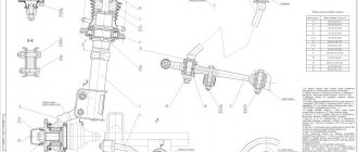
4. SAMPLE CHARACTERISTICS
The type of test sample is shown in Fig. 1. The sample heads, intended for mounting in the grips of the KiVI-50 machine, are made of solid material and are attached to the sample body by welding. There are flats on the sample heads that prevent them from turning in the grips of the machine. Sample material – steel st.Z.
Fig.1. Type of test sample:
1 – sample body,
2 – sample head,
3 – weld
5. BASIC THEORETICAL PROVISIONS
During shear in the elastic stage (Fig. 2), Hooke’s law is valid, which establishes a direct proportional relationship between the shear stress (τ) and the shear angle (γ):
τ= G γ
The value G is a coefficient of proportionality and is called the modulus of elasticity of the second kind or the shear modulus. Hooke's law is valid at stresses not
exceeding the proportionality limit – Tpts.
Rice. 2. Shear deformation
When a round rod is torsioned, its elements are in a state of pure shear (Fig. 3).
Considering that during torsion the stresses – τ depend on the torque Μ, and the twist angle – φ on the shear angle – γ, we obtain the expression for Hooke’s law during torsion:
(1)
where: γ – twist angle, radian
Mk – torque, Η m
I – sample length, m
G – shear modulus. Pa
Jp is the polar moment of inertia (m4), which for a hollow shaft is equal to:
(2)
where: dH – outer diameter
dB – internal diameter of the section.
Fig.3. Torsional stresses and strains
With known values of i and Jp, it is possible, by measuring the torque Mk and the corresponding angle of twist, to calculate the value of the shear modulus G, expressing it from formula (1):
%
(3)
The angle of twist (φ) is determined using a device attached to the body of the sample (Fig. 4).
The device for measuring the angle of twist consists of two levers 3 and 4 rigidly mounted on sample 1 at a distance i from each other. A dial indicator 2 is mounted on lever 3, the measuring tip of which is in contact with lever 4. When the sample is twisted, mutual movement (Δ) of the ends of both levers occurs, which is measured using indicator 2 (Fig. 5). The angle of twist of the sample (Δφ= tgAcp, due to the smallness of this angle) is equal to:
(4)
where: Δ – mutual displacement of the ends of levers 3 and 4, measured by indicator 2;
Ki is the distance from the sample axis to the measuring tip of the indicator, shown in Fig. 5 (Ki = gn + a).
Fig.4. Sample with a device for measuring the angle of twist
6. TEST PROCEDURE
1. Before the test, students need to familiarize themselves with the design of the KM-50 machine (first lesson) and the rules of behavior in the laboratory during testing (introductory briefing).
Fig.5. Twist angle measurement diagram
2. Using a caliper, measure the characteristic linear dimensions of the test sample, the distance between the clamps of the device for measuring the angle of twist and from the generatrix of the sample to the center of the tip of the dial indicator (“a” in Fig. 5).
3. When starting the test, it is necessary to give a preliminary small load to eliminate gaps and compress the sample, and carry out the first readings on the instruments (force meter and indicator), it is better, if possible, to install the instruments
4. Manually carry out static loading of the sample with a torque in equal steps ΔΜΚ. Loading should be done smoothly, without jerking the handle.
5. After each increase in torque by the amount ΔΜΚ, a count is taken from the indicator (the number of indicator divisions). The readings are recorded in the table, columns 1 and 3.
6. During the testing process, carefully monitor the teacher’s comments and, upon completion of the testing, upon his instructions, begin processing the test results.
7. PROCESSING OF TEST RESULTS
The test results are processed using a table. At each stage of torque increment ΔΜΚ, the increments of readings are determined by the indicator ΔΑ, subtracting its readings at the previous loading stage from the reading of indicator A at each loading stage. The obtained results ΔΑ are recorded in column 4.
The twist angle (in minutes) for each torque value (column 1) is determined by the formula:
The obtained twist angle values are entered in column 5.
The average increment of samples AcrA is determined by summing the increments of samples ΔΑ (column 4) and then dividing by the number of increments of samples:
where η is the number of sample increments.
The average angle of twist (in radians) is determined by dividing the average increment of readings A by the radius R
(5)
The shear modulus G is determined by formula (3), taking into account the fact that we do not take the full angles of torsion, but their average increments, i.e.:
where: t is the estimated length (the distance between the attachment points of the clamps of the device for measuring the angle of twist on the test sample);
Jp is the polar moment of inertia of the sample cross-section, determined by formula (2);
Mk – average increment of torque; Lsrf – average angle of twist (in radians) on the base
length , is determined by formula (5).
To check the validity of Hooke's law during this test, a graph is plotted in coordinates (φ - Mk). The torsion angles (q>j) are plotted along the abscissa axis, and the corresponding torques (M-,-) are plotted along the ordinate axis. The resulting points are connected to each other by straight segments. Ideally, the points on the diagram should lie on the same straight line. The farther these points are from the straight line, the worse the sample material obeys Hooke’s law. There is a relationship between the elastic modulus of the first kind (E), the elastic modulus of the second kind (G) and Poisson's ratio (μ):
Therefore, when analyzing the test results obtained and subsequent conclusions, you need to use the previously obtained values for Ε and μ (laboratory work No. 3), calculate the shear modulus G and compare it with that found in this test.