Functional diagram of spot welding
Spot welding requires a current pulse of several hundred amperes. Often a transformer from a microwave is used as a current source. I didn’t want to mess with transformers because of their gigantic size and weight, and I’ll take a pair of 3000 Farad ionistors as a source.
The welding power is selected depending on the thickness of the nickel-plated tape. To connect batteries, tapes with a thickness of 0.1 mm - 0.3 mm are used.
Scheme of spot welding on ionistors and mosfets.
The one-shot on timer 555 generates a single pulse when the green button is pressed. A 10k variable resistor allows you to adjust the pulse duration from 5 to 30 ms. A pulse with a longer duration causes local overheating of the welding site and deteriorates the quality of the connection.
The generated pulse is sent to the TC4420 power transistor driver, which can abruptly open or close an assembly of IRF1324 power switches.
Current-voltage characteristic of the IRF1324 transistor
According to the current-voltage characteristic, it is clear that at a voltage of 5 V one transistor can produce a current of more than 100 A. An assembly of 4 mosfets will produce currents of approximately 500 A. And at 7.5 V more than 1000 A
For sharper operation of power switches on the gates, it is advisable to generate a voltage of 7 - 12V. This reduces transients and reduces transistor heating.
To increase the voltage from 5 V to 12 V, I’ll take a ready-made DC-DC booster. At the output of the booster, a capacitor of 470 - 1000 μF is required. It is this that powers the circuit during welding, and the diode located in the booster prevents the capacitor from quickly discharging when the welding electrodes are short-circuited.
The 5 V 3 A power supply recharges the ionistors during breaks between welding pulses.
A prototype board assembled on a breadboard.
Device with delay function
Let's move directly to the time relay. In this article we will analyze, on the one hand, a circuit that is as simple as possible, but on the other hand, it does not have galvanic isolation.
Attention! Assembly and adjustment of the circuit in question without galvanic isolation should be performed only by specialists with the appropriate education and approvals.
The device is dangerous because it contains dangerous voltage. Such a device in its design has 15 elements and is divided into two parts:
- Supply voltage generation unit or power supply unit;
- Node with temporary controller.
The power supply operates on a transformerless principle. Its design includes components R1, C1, VD1, VD2, C3 and VD3. The 12 V supply voltage itself is formed on the zener diode VD3 and smoothed by capacitor C3.
The second part of the circuit includes an integrated timer with a fitting.
We described the role of capacitor C4 and resistor R2 above, and now, using the previously stated formula, we can calculate the value of the relay delay time: T = 1.1 * R2 * C4 = 1.1 * 680000 * 0.0001 = 75 seconds ≈ 1.5 minutes By changing the values of R2-C4, you You can independently determine the delay time you need and remake the circuit yourself for any time interval.
The operating principle of the circuit is as follows. After the device is connected to the network and the supply voltage appears on the zener diode VD3, and, consequently, on the NE555 chip, the capacitor begins to charge until the voltage at inputs 2 and 6 of the NE555 chip drops below 1/3 of the supply, that is, to approximately 4 V. After this event occurs, a control voltage will appear at the OUT output, which will start (turn on) relay K1. The relay, in turn, will close the load HL1.
Diode VD4 accelerates the discharge of capacitor C4 after turning off the power so that after quickly reconnecting the device to the network, the response time is not reduced. Diode VD5 dampens the inductive surge from K1, thereby protecting the circuit. C2 is used to filter interference from the NE555 power supply.
If the parts are selected correctly and the elements are installed without errors, then the device does not need to be configured.
When testing the circuit, in order not to wait a minute and a half, it is necessary to reduce the resistance R1 to a value of 68–100 kOhm.
You probably noticed that there is no transistor in the circuit that would turn on relay K1. This was done not out of economy, but because of the sufficient reliability of output 3 (OUT) of the DD1 chip. The NE555 microcircuit can withstand a maximum load of up to ±225 mA at the OUT output.
This scheme is ideal for monitoring the operating time of ventilation devices installed in bathrooms and other utility rooms. Due to its presence, the fans are turned on only if they are present in the room for a long time. This mode significantly reduces electrical energy consumption and extends the service life of fans due to less wear of rubbing parts.
Electrical circuit layout of printed circuit board
Two blue LEDs connected in series begin to glow just at a voltage of 5 V. They form a battery readiness indicator. I added a yellow electrode contact indicator. I made a circuit and laid out the board in the EasyEDA editor
Circuit based on SMD components
DIY spot welder
In this tutorial we will look at how to make a small spot welder. It is small in size, all the elements fit inside the computer power supply. The author's electrodes are installed in such a way that when welding, two points are formed at once. Everything is assembled quite simply, and the materials are easily available.
A transformer and a timer module are used as the basis. When you press the start button of the device, the timer starts welding for a short time, resulting in a welding point. If you wish, you can set the device for any period of time; if the metal is thick, the timer can be adjusted for a longer time. So let's get started.
Materials and tools used by the author: List of materials:
— timer module; — transformer (the author has 800 watts); — screw terminals for wires; — copper wire 1.7 mm thick; — power wire (8 mm); — power supply 12V, 0.5A; - switch; - old computer power supply; — heat shrinkage; — mounting angles; - wooden block; - spring; — plastic clamps; - screws and nuts and other small items.
Toolbar:
- drill; - rivet gun; — dremel; - screwdrivers; - pliers; - wire cutters; - soldering iron; - glue gun; - hammer.
Welding machine manufacturing process:
Step one. Preparing the body
The author used an old computer power supply as the case. We disassemble it all and extract all the contents. You will only need to leave one “socket”, which will supply power.
Once the transformer is installed, we proceed to install the timer module. It has an adjustment knob, with the help of it and a nut the module is attached to the body. Drill a hole and screw the module. Just in case, cover the open contacts with adhesive tape to prevent a short circuit.
Finally, install the switch; the author mounts it in the place where there used to be an outlet. We attach the switch from the inside using hot glue.
Step four. Assembling the circuit
You can see in the photo how to connect everything. The transformer is connected to the network in a gap through a timer; it will turn on the transformer for a specified time after pressing the button. The timer needs 12V power, for this we need to install a power supply inside the case. The author cuts off the plug from the power supply for easy installation, solders the wires and insulates the soldering points with heat shrink. The power supply can be fixed with hot glue so that it does not dangle inside.
Well, then we assemble everything as in the diagram.
Now you can secure the ends of the power wires. For this job you will need screw clamps. We install them on the ends of the wires, and then screw the clamps themselves to the lever using self-tapping screws.
You also need to install a trigger button at the end of the lever. We drill a hole in the lever for it and install it with hot glue or another method. To prevent the wires from dangling, we fix them with plastic ties.
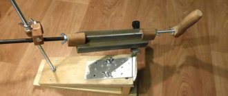
Housing and mechanical assembly
Once assembled, it turned out to be a fully functional machine for spot welding. I installed the control board on an assembly of ionistors.
Factory board and mounted SMD components
To hide the guts, I modeled the case cover in Fusion360 and printed it on a 3D printer. The new version is a little different, because... made for factory board.
Assembled spotter with 2 ionistors.
One ionistor for 3000 F cost approximately 1900 rubles. The entire spotter costs much less than even Chinese welders and copes with 0.1 - 0.12 mm tape.
Spot welding option with 3 ionistors.
The board is quite universal. It can be used for more powerful welding on 3 ionistors with a voltage of 7.5V. In such an assembly, the DC-DC booster can be replaced with a Schottky diode, and instead of one of the 2 blue LEDs, a 5.1 V sabilitron can be used. Naturally, for charging you will need a 7.5 V 3A power supply. This spotter copes with tape up to 0.3 mm
The spotter's functionality is sufficient for a home workshop. However, you can add delayed auto-start when the electrodes touch the tape. You can also add a display to indicate parameters and select operating modes. You can also do a double welding pulse.
If you liked the project, support the author! This motivates you to create useful homemade products!
SUPPORT THE AUTHOR
You can also order a kit for self-assembly of CapWelder with all the necessary materials, except for ionistors and a power supply. You can order them yourself using this link.
Order a set for 1900 rubles
or order a ready-made board with SMD components
Order an SMD board for 1,490 rubles
The package with the kit will contain all components, incl. printed circuit board, housing and all elements except IONISTORS and power supply. The proceeds will be used to purchase materials for new projects, equipment for filming, website maintenance and a domain name.
How does the 555 chip work?
Before moving on to the example of a relay device, let's consider the structure of the microcircuit. All further descriptions will be made for the NE555 manufactured by Texas Instruments.
As can be seen from the figure, the basis is an RS flip-flop with an inverse output, controlled by outputs from comparators. The positive input of the upper comparator is called THRESHOLD, the negative input of the lower one is called TRIGGER. Other comparator inputs are connected to a supply voltage divider consisting of three 5 kOhm resistors.
As you most likely know, an RS flip-flop can be in a steady state (it has a memory effect of 1 bit) either in a logical “0” or in a logical “1”. How it works:
- The arrival of a positive pulse at input R (RESET) sets the output to logical “1” (namely “1”, not “0”, since the trigger is inverse - this is indicated by the circle at the trigger output);
- The arrival of a positive pulse at input S (SET) sets the output to logical “0”.
Three 5 kOhm resistors divide the supply voltage by 3, which leads to the fact that the reference voltage of the upper comparator (the “–” input of the comparator, also known as the CONTROL VOLTAGE input of the microcircuit) is 2/3 Vcc. The reference voltage of the lower one is 1/3 Vcc.
With this in mind, it is possible to create tables of states of the microcircuit regarding the TRIGGER, THRESHOLD inputs and OUT output. Note that the OUT output is the inverted signal from the RS flip-flop.
| THRESHOLD < 2/3 Vcc | THRESHOLD > 2/3 Vcc | |
| TRIGGER < 1/3 Vcc | OUT = log "1" | undefined state OUT |
| TRIGGER > 1/3 Vcc | OUT remains unchanged | OUT = log "0" |
Using this functionality of the microcircuit, you can easily make various signal generators with a generation frequency independent of the supply voltage.
In our case, to create a time relay, the following trick is used: the TRIGGER and THRESHOLD inputs are combined together and a signal is supplied to them from the RC chain. The state table in this case will look like this:
| OUT | |
| THRESHOLD, TRIGGER < 1/3 Vcc | OUT = log "1" |
| 1/3 Vcc < THRESHOLD, TRIGGER < 2/3 Vcc | OUT remains unchanged |
| THRESHOLD, TRIGGER > 2/3 Vcc | OUT = log "0" |
The NE555 connection diagram for this case is as follows:
After power is applied, the capacitor begins to charge, which leads to a gradual increase in the voltage across the capacitor from 0V onwards. In turn, the voltage at the TRIGGER and THRESHOLD inputs will, on the contrary, decrease, starting from Vcc+. As can be seen from the state table, there is a logical “0” at the OUT output after Vcc+ is applied, and the OUT output switches to a logical “1” when the voltage at the indicated TRIGGER and THRESHOLD inputs drops below 1/3 Vcc.
The important fact is that the relay delay time, that is, the time interval between applying power and charging the capacitor until the OUT output switches to logical “1”, can be calculated using a very simple formula:
T = 1.1 * R * C And as you can see, this time does not depend on supply voltage.
Consequently, when designing a time relay circuit, you don’t have to worry about power stability, which significantly simplifies the circuit design. Next, we present a drawing of a variant of the microcircuit in a DIP package and show the location of the chip pins:
It is also worth mentioning that in addition to the 555 series, the 556 series in a package with 14 pins. The 556 series contains two 555 timers.
Required materials
- Timer NE555
- MOSFET TC4420 driver
- Power switches IRF1324 - 4 pcs.
- Ionistors for 3000 F 2.8 V - 2 pcs or 3 pcs (for version 7.5V)
- Power supply 5 V 3 A or PSU 7.5 V (for version 7.5V)
- Gerber PCB file
- Or a development board like in the video
- Potentiometer 10kOhm
- Soft wire for connecting electrodes PUGV 1x6 mm2 - 1 m
- Rigid wire PuVng 1x4 mm2 - 0.1 m
- Terminal blocks for making an electrode handle
- Ferrules for wire 6x6 mm2 - 4 pcs or 6 pcs (for version 7.5V)
- Blue LED - 1 pc.
- Zener diode BZX55C3V9 at 3.9V or BZX55C5V1 at 5.1V (for the 7.5V version) - 1 pc.
- Yellow LED - 1 pc.
- Resistor 4.7 kOhm 1206 — 2 pcs.
- Resistor 2.2 kOhm 1206 — 1 pc.
- Resistor 100 Ohm 1206 - 1 pc.
- Resistor 220 Ohm or 390 Ohm (for version 7.5V) 1206 - 1 pc.
- Capacitor 4.7 nF 50 V 0805 — 1 pc.
- Capacitor 2.2 uF 25V 1206 — 1 pc.
- Electrolytic capacitor 470 uF 25V - 1 pc.
- Power socket
- Green button
- Power button
- DC-DC booster 5V - 12V or Schottky diode 1N5818 (for 7.5V version)
- Stl file 3D model of the case for printing
How to make a relay with a switch-off delay
The above circuit, thanks to the features of the NE555, can be easily converted into a shutdown delay timer. To do this, you need to swap C4 and R2-VD4. In this case, K1 will close the load HL1 immediately after turning on the device. The load will be turned off after the voltage on capacitor C4 increases to 2/3 of the supply voltage, that is, to approximately 8 V.
The disadvantage of this modification is the fact that after disconnecting the load, the circuit will remain exposed to dangerous voltage. This drawback can be eliminated by connecting a relay contact to the power supply circuit to the timer in parallel with the power button (namely a button, not a switch!).
The diagram of such a device, taking into account all the modifications, is shown below:
Attention! In order for dangerous voltage to actually be removed from the circuit by the relay contact, it is necessary that the PHASE be connected exactly as shown in the diagram.
Please note that the 555 timer is used and described on our website in another article, which discusses a time relay circuit with a 220V turn-off delay. The circuit presented there is more reliable, contains galvanic isolation and allows you to change the time delay interval using a regulator.
If you need a printed circuit board drawing when making a product, write about it in the comments.
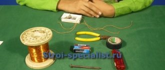
Transformer
The transformer is taken from a 500-watt audio power amplifier. The cross-sectional area of the magnetic circuit is 23 cm/2. Despite its small size, the transformer has significant power. The secondary winding must be rewound. It should consist of a 2 meter wire with a cross section of 35mm/2 (10mm insulation). The window dimensions of 46.5 x 9.5 mm made it possible to fit four turns of wire. They provide 2.6 V and almost 1000 A short circuit current. This transformer, compared to a microwave oven transformer, has the advantage that there is no need to install a cooling fan. Numerous openings in the case provide passive cooling.
results
The welding machine can easily handle 2 x 0.75 mm sheets - the seam cannot be torn apart without tearing out the metal. Perhaps if the electrodes are thicker and pointed at the ends, it will be possible to weld thicker sheets. Aluminum brackets conduct heat from the electrodes quite well, so welding can be done without much worry about overheating and melting the wire insulation. Schematic, printed circuit board, firmware file, sources, etc. - everything is in the archive for downloading.
Welding Equipment Forum
Timer operation:
We connect the power transformer (variable 9-12V) and the pedal to the corresponding terminal blocks, the wires going to the microwave power transformer are soldered. There are two knobs on the board - the left one for adjusting the welding time delay, the right one for adjusting the current. On the remote display you can see numbers that similarly show the time delay on the left and the current on the right. The welding time delay is adjustable from 1 to 50, 1 is one network period, that is, 0.02 seconds. That is, the timer can set shutter speeds up to 50 * 0.02 = 1 second. The welding current is adjustable from 30 to 99.
When you press the pedal, the microcontroller monitors the voltage in the 220 volt network, and at the peak or bottom of the sine wave it gives a signal to the triac. While the thyristor is open, current flows through the primary of the welding transformer and welding occurs. The board works like an electronic switch or key. When the time value is 1 on the display and the current value is 99, the timer turns on the triac for 20 ms, for one network period. If you need less, you can reduce the current with the right regulator and the controller will open the triac not to the full sine wave, but only to part of it.
I took oscillograms from the secondary winding of the welding transformer at different current values and shutter speeds, they can be seen in the photo below:
The point of adjusting the current is that if the transformer is too powerful for welding 18650 batteries and other similar ones, and the time delay of 0.02 seconds is too long and burns through the plate or batteries, then you can further reduce the current - the pulse will become weaker and the batteries will not burn through. I tried to cook a nickel plate at shutter speed 1 and currents from 30 (rightmost) to 99 (leftmost), the result is clearly visible. This can be seen in the photo below. The plate is 8 mm wide, 0.15 mm thick.
I tried to do the last two welding tests using a long shutter speed and low current. With a holding time of 10 and 30 and a current of 30, the plate heats up, even changes color, but does not weld. For welding thin nickel plates, a short pulse with a high current is better than a long pulse with a weak current.
The last points on the left, one of them is through, were made precisely at shutter speeds of 10 and 30 and a low welding current value of 30. All this can be clearly seen in the video version of the review below:
source