Boring of holes is the processing of internal cylindrical or conical surfaces with a blade cutting tool to give them the required size, cleanliness class, straightness or a given position relative to the axis of rotation. The original holes in forged and cast parts, as well as those obtained as a result of drilling, are subjected to boring. In addition, this processing method is used to restore the cylindrical shape of working surfaces lost as a result of wear, deformation or damage. In this case, the surface is subjected to surfacing before processing, if necessary.
Boring has lower productivity than drilling, but allows you to process cylindrical surfaces of large diameter (more than a thousand millimeters) with an accuracy of several tens of microns. For boring, both universal and specialized machines of the turning and milling groups are used. In the first case, the workpiece rotates, and the tool (cutter) moves linearly in accordance with the longitudinal and transverse feeds. In the second, the boring head rotates in the spindle, and the feed can be assigned to both the tool and the part mounted on the work table.
Boring through holes
Depending on the size of the hole (depth and diameter), for through boring, through cutters, mandrels or boring bars are used, on which boring heads or cutter blocks are installed. Pass-through cutters for boring through holes have a number of differences from turning tools for external turning: their rear corner is sharpened so that the cutting part corresponds to the processing size, and the front part of the holder is narrowed and has an elongated shape. On lathes, the cutter is mounted either in a mandrel with a conical shank on the tailstock, or on a caliper tool holder in the longitudinal direction. Boring machines use cutters that are installed in special mandrels.
For through boring, multi-edge mandrels of various designs are also used, having the form of a thick elongated cylinder on which several cutting plates are located. Such a tool is much more expensive than cutters, but allows you to process much greater depths and with better accuracy.
Boring bars (boring bars) are used for boring with great depth, increased accuracy or several coaxial holes. This type of tool is made in the form of long cylindrical rods of increased precision with a diameter of 30 to 200 mm and a length of one to three meters. Along the entire length of the boring bar, at a certain distance, there are through recesses (windows) for attaching a cutting or measuring tool. One end of the boring bar is attached to a conical mandrel and installed in the spindle, and the other is supported by a steady rest or a special support. Before boring, the axes of the holes and boring bars must be aligned to the specified accuracy.
Boring holes
Boring is used for machining holes of various sizes and shapes in hollow workpieces with an accuracy of up to 9th grade and a roughness of up to Ra=l microns. Pre-drilled holes or holes in casting or forging (stamping) workpieces are often bored to increase the diameter, provide high dimensional accuracy and a high grade of surface roughness. Boring of holes ensures a diameter tolerance of up to 0.02 mm and a 6th class roughness. By boring you can correct the position of the hole axis.
Boring is the most versatile method for making holes. But at the same time, this method is not very productive, mainly due to the insufficient rigidity of the boring cutters.
Boring cutters are divided by design into solid and holder (Figure 61), and by purpose - for through holes (Figure 61, a) and blind holes (Figure 61, b).
Due to the insufficient rigidity of solid cutters, they can only be used for boring holes up to three diameters deep. Turning of deeper holes with a diameter of approximately over 30 mm is carried out with holder cutters. Such cutters are made in two varieties: with direct fastening of the cutter J in holder 2 (Fig. 61, c) - for through holes, and with oblique fastening (Fig. 61, d) - for blind holes. Flats 3 on the holder serve for a stable position of the cutters in the tool holder.
According to current standards, solid boring cutters (Fig. 62) are available in two versions. Cutters of execution A with a round working part of the rod are designed for processing holes with a smallest bore diameter of 10 mm, cutters of execution B with a rectangular cross-section of the rod are for holes of 40 mm. Their geometric parameters are shown in Fig. 62, c and d.
In addition, the standards allow the production of two types of cutters: with a lowered head (Fig. 62, a) with the cutting edge located along the axis of the cutter and with a normal head (Fig. 62, b). The former have greater rigidity, since they allow the diameter of the rod to be approximately doubled due to its more rational placement in the hole.
Boring cutters are installed parallel to the axis of the hole being machined and secured in the tool holder with the least possible overhang. Their top should be at the level of the center axis of the machine or slightly higher (by about 0.02 of the hole diameter) to compensate for possible deflection.
Boring blind holes
When boring blind holes, stop cutters or mandrels with inclined cutting plates are used. In both cases, the problem of processing the bottom (inner end) of the hole arises, since in the middle there remains a small conical zone that is not touched by the cutter. Therefore, such boring is performed in the following sequence:
- drilling (or reaming a hole) to the maximum possible diameter;
- rough boring, after which an allowance of several millimeters remains;
- processing the bottom of the hole with a special end trim to the required cleanliness;
- finishing boring to a given size.
When blind boring, special attention is paid to machining near the bottom of the hole. Therefore, 5 mm before reaching the full depth, the feed should be reduced, and the last section should preferably be done manually. Passing cutters are used only for small boring depths (100÷150 mm). In all other cases, boring heads of various types are used.
FINISH SPEED BORING OF DEEP HOLES
Section: LIBRARY OF TECHNICAL LITERATURE Short path https://bibt.ruBook contents Previous Next
The process of processing deep holes, if a surface roughness above class 4 according to GOST 2789-59 is required, usually includes three operations: drilling, preliminary boring and finishing boring.
The purpose of pre-boring is to obtain a straight-axis hole of the required size with the minimum necessary allowance for finishing boring.
In the recent past, of the three listed operations, fine boring was the most labor-intensive, since the work was carried out with a high-speed tool at relatively low cutting conditions.
In recent years, high-speed processing methods based on the use of carbide tools have been used in all machining operations of deep holes with a diameter of up to 150 mm. This made it possible to increase productivity several times, and currently fine boring has become the most productive of all these operations. For example, one pass when processing a hole with a diameter of 80-100 mm and a length of 6-7 m requires no more than 5-10 minutes. machine time. Recommended cutting modes are given in table. 34.
Table 34 Cutting conditions recommended for high-speed finishing boring of deep holes in steel with hardness Hb = 270 - 320
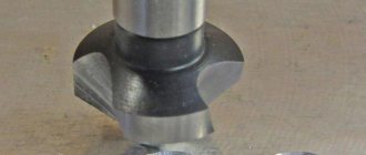
Fig. 55. Floating insert for high-speed finishing boring of deep holes.
Boring is carried out by floating measuring plates (Fig. 55), installed with a second-class running fit in groove 1 of the boring head (see Fig. 56).
To obtain sufficiently thin chips necessary to achieve class 6 roughness, when working with the feeds indicated in table. 34, the angle is made no more than 1°30′.
With such a small angle and high cutting speed, strong vibrations are inevitable. As a result, the success of high-speed finishing boring of deep holes is largely determined by the perfection of the vibration damping means used.
Fig. 56. Boring head with rubber guides.
For this purpose, boring heads are used (Fig. 56) with rubber guides 4, the diameter of which is 1.3 mm larger than the diameter of the boring plate. A flywheel is placed on the bar. The required bore diameter is set using wedges 1 and 5, nut 2 and lock nut 3. The rubber used for the guide heads must have a temporary tensile strength => 100 kg/cm2, relative elongation => 450%, residual elongation <=50%, Shore hardness 55-65.
When processing heavy parts, the required high cutting speed is achieved by slow rotation of the workpiece and rapid counter-rotation of the rod, carried out from a special gearbox installed at the rear rack of the machine. In this case, rubber guides on the boring head and flywheels on the stem alone are not enough to dampen vibrations. In addition to this, a special vibration-damping device is installed in the front post, which serves as a support for the stem (boring bar), (Fig. 57). In a fixed housing 1 fixed in the front pillar, cups 2 and 3 are inserted with angular contact bearings 4, tightly seated on the sleeve 5. The rod is clamped by a cast iron ring 6, consisting of four parts, interconnected by rubber cylinders 7, which play a role elastic link that absorbs vibrations. The fastening force is created by nut 8 and transmitted to ring 6 through bearings 9 and ring 10.
Fig. 57. Vibration damping device for the boring head.
Skip to navigation
Boring hole restoration technology
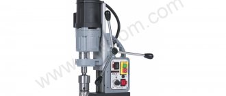
Using boring, cylindrical surfaces that have been worn out during intensive use are restored. Such repairs can be performed both in stationary conditions on lathes and boring machines (vertical and horizontal), and using mobile units in the field. Lathes are indispensable in cases where it is necessary to restore the accuracy and alignment of several mounting holes. And boring machines are usually used in cases where increased accuracy is required or the part has large dimensions. A clear example of the massive use of vertical boring machines in equipment repair is the restoration of cylinder surfaces of internal combustion engine blocks.
Mobile units are used for boring cylindrical surfaces directly at the site of equipment operation. This method is used to bore holes in the eyes of mining equipment buckets, rotation surfaces of mining machines, flanges and shut-off valves of existing pipelines, seats for power equipment, and much more.
A typical mobile installation consists of an electric drive with a spindle and chuck, a boring bar with a cutting tool, rear and intermediate supports. All its components are attached directly to the workpiece, and rigidity, accuracy and alignment are ensured by the boring bar.
Turning modes
A turner chooses a technology depending on many factors:
- workpiece material, its strength;
- cylinder parameters;
- accuracy of machine adjustment;
- cutter used, etc.
In accordance with this, the rotation speed, feed and some other factors are adjusted. Let's look at it below.
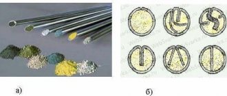
Restoration of holes by surfacing
When restorative boring of cylindrical surfaces, their diameter increases significantly, sometimes by several millimeters. And if when repairing internal combustion engines this problem is solved by using larger repair pistons and liners, then for other types of equipment the rough size of the hole is restored by applying a layer of metal to its surface. For these purposes, various types of welding are used, as well as spraying and tinning. After restoring the size of the hole by surfacing, it is bored to the required dimensions. This technology is one of the most widespread, so manufacturers of repair equipment, in addition to boring and welding installations, offer consumers comprehensive solutions: boring and surfacing kits of various sizes and power.
Has anyone had to actually participate in boring holes on mobile boring machines? If yes, please tell us in the comments how such devices are mounted and positioned, as well as how their accuracy and alignment are adjusted.