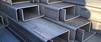
A channel is one of the main elements that make up a metal structure. To form the desired frame structure, welding of channels is required. The welded assembly has good reliability, but any violations in the welding technology can lead to weakening of the entire structure. In this regard, welding is the most difficult and controlled stage in the production of metal structures.
The choice of connection is directly proportional to the size of the structure and the forces acting on it.
The following options for the relative arrangement of channels are distinguished:
The choice of a particular option is associated with:
- suture conditions;
- the length of the welding site and the number of workers involved to apply it;
- type of forces and places of their influence;
- type and overall dimensions of the channel;
- the required design stability and full load on the structure.
Types of welding used
Arc welding
A huge selection of types of electrodes according to their nominal characteristics and the features of their operation provide an undeniable advantage over other types of welding and make it preferable for this task. We will get the best seam if we use UONI electrodes. When working with these electrodes, you should take into account their features and recommendations:
- Where possible, connections should be overlapped.
- To use this electrode, prior experience with it is required.
- Before use, the electrode must be calcined in a special. oven for an hour. Calcination temperature 250 C.
- The joints of products must be cleaned of dirt, rust and prepared in accordance with GOST 5264-80.
- The welder must work with a short arc of medium power, direct current and reverse polarity.
- Metal structures welded with this electrode should not be used at temperatures below - 40 C.
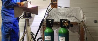
Gas welding
This type is often not used when welding channels due to the huge area and heating temperature. These factors are a source of internal stresses in the metal structure and general deformations that negatively affect the entire metal structure. Nevertheless, gas welding is often used to eliminate flaws in finished structures or to cut workpieces and then remove edges.
Welding types
Butt welding of channels
This connection is used for non-critical structures. Welding is performed from the front and back sides and with the condition of good penetration thickness. The installation seam is first performed on the thin and then on the thicker part of the channel. It is allowed to make this seam on one side of the product with the obligatory welding of the root of the seam.
Sequence of sutures
The need for edge removal is determined based on the thickness of the channel flanges:
- 6 mm or less - no bevel of edges required.
- 6-12 mm - the bevel is made at an angle of 30.
- 12 mm and more - the bevel of the edges is made at an obtuse angle on the inside of the workpiece. The seam is made V and X-shaped.
Welding algorithm:
- The channel is placed horizontally with its walls.
- The edges are removed depending on the thickness of the metal.
- Two beams are joined with a gap of no more than 3 mm.
- The workpieces are temporarily tacked together at points in increments of 40 mm.
- The correctness of the created design is analyzed.
- The final welding of the joint surface is carried out continuously from the middle of the wall towards the shelves.
To improve welding characteristics and prevent the appearance of cracks at welding points, it is recommended to reinforce the rolled steel with pads immediately after installing the product. When welding U-shaped bars only at the butt, without overlays, the welded joint will be weaker than the channel itself.
Welding channels with overlays
The gap at the junction of two welded parts is set to no more than 8 mm. The overlay is placed on the side of the weld. The thickness of the reinforcement depends on the welding mode and the size of the rolled product.
It is necessary to go around the reinforcement pads with an electrode along the entire plane. If circular scalding is not possible, fill all gaps with a substance that prevents corrosion.
Welding algorithm:
- The channels are welded end to end in accordance with GOST technological standards.
- The seam inside the channel is smoothed to a plane.
- A reinforcement is welded into the inner part of the channel - a sheet of steel having a length equal to 5 times the width of the channel. The width of the sheet is equal to the width of the channels, the thickness of the sheet is taken equal to the thickness of the channel material. The strip is welded only on the longitudinal sides.
- The second strip is attached as a rib and welded on both sides of the strip. The rib should be well cooked along the contour on both sides and close to the strip.
The strength characteristics of a product spliced using this method will be slightly inferior to a monolith.
Connecting channels inwards
To create a reinforced hollow beam, you can connect two products with shelves inward. Making such a connection is the same as butt welding two channels. This connection is used when medium power structures are required.
Welding algorithm:
- Place the workpieces on shelves horizontally opposite each other.
- Secure with clamps.
- Make the seam either according to GOST with separation of the edges, or leave a gap (the size of the gap is chosen depending on the thickness of the channel, but not less than 3 mm).
- The seam must be made using the tack method or from the middle to the edges.
Cleaning the seams with a grinder in this connection is strictly prohibited and can lead to weakening of the entire structure.
It is possible to assemble this configuration in conditions unsuitable for this work when assembling the structure only when welding is carried out in a horizontal plane and in a lower position. In other cases, it would be more reasonable and simple to use butt seams with their reinforcement with lining sheets.
Offset connection
This welded structure is produced by several welders and is used to combine channels with different geometric dimensions. Welding begins from places with thicker metal. Butt joints are made in accordance with standard standards, and corner joints must be made simultaneously with two welds (from edge to middle). Longitudinal seams cannot be applied to the end of the beam. This distance depends on the materials being joined and the area of the rolled shelf. For carbon steels, this distance is equal to the width of the flange, and for alloy metals it is equal to twice its width.
When assembling metal structures of varying degrees of complexity and configuration, the methods and types of welding channels listed above are used. Any metal structure can be divided into separate small independent node connections in which the above methods will be applicable.
The most durable connection method among all types is considered to be the connection of equal-flange bars with parallel flanges.
Any welding of channels or I-beams requires compliance with a predetermined series of actions and the exact order of installation work. The assembly of any metal structure should always begin from the middle and move towards the edges; at the same time, welding begins with channels having a thicker metal profile. When assembling, it is not recommended to place welds close to each other; it is better to strengthen these places using backing sheets of metal and auxiliary reinforcing structures. Any weld itself reduces the strength of the entire metal structure by 5-7 percent, although the material of the weld has better strength characteristics than the material of the main part. The welding mode and the speed of applying the weld directly depend on the type of connection you choose, but the best when working with manual electric welding is considered to be 20 m/h.
To create an excellent, strong connection, before welding it is necessary to thoroughly clean the areas of future connections and process the edges in accordance with GOST recommendations. Reinforcement strips after butt welding should only be placed on the outside of the channels. Welding in the inner corners of the channel will weaken the entire structure, so it is not advisable to carry out work in the inner corners of the unit.
Any welded connection weakens the structure and its individual components. Therefore, in construction, to reduce welded joints under increased loads on the support beams of load-bearing structures, it is customary to use channel and I-rolled metal products. Welding a channel during installation of load-bearing parts of a structure is a particularly important stage, but it often causes difficulties and the inability to comply with strict welding rules (GOST).
Welding using pads
This method allows you to create strong seams. Used when installing structures intended for operation under high loads. Stages:
- The channel sections are welded end to end. The seam inside the profile is cleaned to a flat surface.
- An overlay is made. The same steel that was used in the production of U-shaped rolled products is used for it. The thickness of the reinforcing lining must be no less than the thickness of the channel wall. There are several options for the shape of such overlays. One of them is a polygon (6- or 8-gon).
- One polygon is welded from the inside of the profile, the second - on the outer wall. The second has a slightly larger area compared to the internal one.
- The overlays are boiled along the full contour.
Design features of channel connection
General information about the channel
A steel channel is a metal product that has a U-shaped cross-section profile. This design makes it possible to obtain high structural characteristics with minimal consumption of material and metal. The methods of manufacturing channels (by bending on a special machine or by hot rolling) do not affect the choice of welding technique when connecting them, but only on the general strength characteristics.
The main advantages of the channel are aimed at strengthening individual structural units and are:
- Able to withstand large axial loads.
- High resistance to bending under central load.
- Possibility of connection without welding.
And also these same advantages are also disadvantages when welding channels.
Currently, five types of channels are produced:
- special;
- with shelves of different sizes;
- equal-flange;
- with a certain slope of the shelf edges;
- with parallel edges of the shelves.
The greatest joint strength can be achieved by welding equal-flange channels with parallel flange edges. They are the most in demand in the construction industry.
Difficulties in connecting channels
Channels have proven themselves well for prefabricated metal structures, but the smallest errors in their connection cause a critical violation of the strength of the entire structure. Each welded joint itself weakens the strength of the metal structure by 5-7%, despite the fact that the weld metal has higher strength characteristics than the metal of the main part.
The problem lies in the welding technique itself, in the correct preheating of the metal and in the experience of the welder. An inconvenient position when assembling some units, as well as incorrectly selected seams, leads to the fact that the heat-affected welding zone (zone of uneven melting) loses up to 20% of its strength. These are the most vulnerable joints and there are two of them for each weld, on both sides. GOST provides for the most common node connections, but not all.
Result:
- All recommended standards according to GOST cannot be neglected.
- Welding of channels according to GOST is much stronger, even with additional reinforcement of the structure.
- All additional linings afterwards must be performed exclusively on the outside of the channels.
- Welding in the inner corners of the channel only weakens the overall structure, so welding in the inner corners, as well as inside the channel itself, is not advisable.
- You can weld not only according to GOST, as this is sometimes inconvenient, but also based on recommendations.
How to weld I-beams
Steel beams with an I-beam cross-section are designed for universal use in mechanical engineering and construction. When studying the nature of stresses arising in loaded products having a solid cross-section, the unevenness of their distribution was revealed.
Sections of the cross-section of parts with the highest stress values were identified. As a result of this, the idea arose of creating a product with a cross-sectional shape where the mass of metal is concentrated in the most loaded areas. This is how the I-section appeared.
Production and use
Due to their ability to withstand heavy bending loads in different planes, shear and torsion, steel I-beams form the basis of load-bearing structures of prefabricated frame buildings and ceilings.
In-shop lifting mechanisms (beam cranes and overhead cranes) move along guides made from I-beams.
The production of I-beams is carried out in two ways:
- method of rolling solid castings. Such I-beams are called hot-rolled;
- electric arc welding of pre-cut sheet blanks, resulting in a welded prefabricated I-beam.
Hot-rolled I-beams are produced on rolling mills of metallurgical enterprises. This technology makes it possible to obtain a one-piece product that does not contain seams and is highly durable.
Assembly and welding of I-beams is carried out on automatic lines. Such a beam is slightly inferior to a solid-rolled beam in terms of strength, but can be made to special order, taking into account the requirements of a specific project.
The production of hot-rolled I-beams is carried out in accordance with GOST 26020-83; manufacturers produce welded I-beams according to their own technical conditions (TU).
Production technology
In the typical version, an I-beam is made from three sheet blanks: a wall and two flanges, welded to its ends at right angles. Manufacturing is carried out on specialized assembly lines configured to produce beams of a certain size.
The workpieces are moved on special rollers and pre-fixed in the desired position by clamping devices equipped with a hydraulic or pneumatic drive.
On the section of the assembled beam fixed by the clamping device, tacks are made by welding along the waist seam. After this, the beam moves along the rollers, is secured again, and its next section is tacked by welding.
The waist seam is finally welded after the entire structure is pre-fastened with welded tacks.
Welding of T-joints between the wall and the flanges is carried out automatically under a layer of flux. The automatic welding process can be performed with different devices. These can be welding manipulators, the torches of which weld, moving along given trajectories through articulated joints with several degrees of freedom.
Which welding is preferable for connecting channels?
Arc welding
The peculiarities of using electrodes and the possibility of selecting them according to their main characteristics make electric arc welding the most preferable for connecting channels. The highest quality seam is obtained when using, but there are some peculiarities of their use.
The welding mode itself and the speed of the seam depend on the selected type of connection, but the most optimal for manual welding is 20 m/h.
Gas welding
When connecting channels, the use is most often completely abandoned. The heating temperature and a large heating zone, and, accordingly, an even larger heat-affected weak heating zone, do not favor the choice of this joining method. Negative thermal effects, as well as overheating of the weld area, lead to unnecessary internal stress in the metal and severe deformation of the overall structure (beam).
But with subsequent processing of edges, gas welding is often used to correct defects in finished metal structures.
Types of joining channels
The choice of connection is directly proportional to the size of the structure and the forces acting on it.
The following options for the relative arrangement of channels are distinguished:
- the channel shelves are facing inward;
- the channel flanges face outward (forms an I-beam);
- mixed arrangement of shelves;
- the channel flanges are perpendicular to the plane of the frame;
- diagonal placement (standing or lying down).
The choice of a particular option is associated with:
- suture conditions;
- the length of the welding site and the number of workers involved to apply it;
- type of forces and places of their influence;
- type and overall dimensions of the channel;
- the required design stability and full load on the structure.
The most common metal structures made from channels
Beams and possible options for their welding
Butt connection between identical channels. Overhead assembly seams are made on thin metal (1,2), and then on thicker metal 3. The connection is used to obtain low-power structures.
After making butt joints, a fillet weld (4) is often additionally used. In this case, longitudinal seams never extend to the end of the beam at a distance that depends on the metals being welded and the width of the channel flange. So for low-carbon steel this distance is equal to the width of the flange (B), and for alloy metals - two dimensions of the flanges (2B). To perform structures of medium power, this type of connection is used.
This connection is made by two welders and is used for welding channels with flanges of different thicknesses. The first seam is made for thicker metal (1). The butt connection (3) is carried out according to the rules, and the corner connections (4) must be carried out simultaneously by two welders (from the edges of the beam to the middle).
In the manufacture of more complex metal structures, the same welding methods are used. The entire structure is divided into separate node connections, in which the channels are welded. Installation of the structure always begins from the middle to the edges and with channels made of thicker metal, and then from thinner ones. It is not advisable to place seams close to each other; it is better to use metal linings and additional structural reinforcements.
Connecting channels requires a certain sequence of actions and a precise installation plan. The importance of each seam cannot be underestimated, since there is a high risk of losing all the benefits of using channels for the strength of structures.
Before considering the features of channel welding
, let us briefly explain the specifics of this product itself.
The channel
is manufactured by pressing and hot rolling and differs from other metal products in its specific U-shaped section. The latter, in turn, helps to achieve high structural performance in combination with minimal metal consumption.
As a rule, channels are made of aluminum, carbon and low-alloy steel. Products of measured, multiple measured and unmeasured lengths are distinguished. Channels find a wide range of applications in construction, repair, manufacturing and many other areas.
The choice of channel welding method depends, first of all, on the expected operating conditions, in particular on the loads on the structure. As is known, welding joints to some extent weaken its strength, therefore, for welding channels, the highest quality welds are created. The high quality of the weld is ensured with the help of electrodes - special metal rods through which current flows. Electrodes can give the weld strength, durability and resistance to corrosion.
Relatively small channels can be welded with conventional electrodes
, but larger products require a special approach.
UONI electrodes
successfully cope with the tasks of welding the most critical structural components , however, they require a certain skill in use, and therefore you should first practice on workpieces similar to the future design. The big advantage of using this particular type of electrode is that they do not have any restrictions on the welding method: they can even be welded with a vertical seam, which is formed from top to bottom.
Before welding channels, a number of general measures
which are required for joining parts with thick edges, namely:
form a V or X-shaped section
, grinding off the edges at an angle from 30 to 60 degrees.
Another important point in the preparatory stage is drying the electrodes
, which is necessary due to the fact that the strength of the future seam directly depends on the humidity of the coating of the electrode used.
During operation, the polarity should be reversed and the current should be constant, while the welding itself is carried out with a short arc on the polar side. The welding process must be carried out at an ambient temperature of at least minus 40 degrees. Immediately before welding, it is necessary to thoroughly remove dirt and rust from the metal.
In most cases, welding of channels is carried out with the flanges inward
.
To do this, you must first cut the edges
. If the edges are not cut, then welding is carried out with a gap of about 3 mm. This is done in order not to provoke welding on the metal, which will subsequently weaken the welding seam. To make a seam correctly, you need to first weld the thicker elements, and additionally weld all the overlays along the contour. The absence of this action can contribute to the rapid development of corrosion and subsequent rupture of the entire structure. The exact calcination time depends on the specific brand of electrodes, but usually ranges from one to two hours.
If it is difficult for you to weld channels without an assistant, you can use clamps and weld directly with tacks. First, a seam is made from one end of the channel, then from the other. Next, you should weld from different sides and ends, because if you first weld one seam completely, then the other runs the risk of coming apart. The most recommended position of the seam is the lower horizontal one. During the welding process, it is important to monitor the angle of inclination of the electrode to the plane being welded - it should be in the range from 40 to 70 degrees.
Above, we examined in detail the most common option for welding channels with flanges inward. However, it is necessary to mention other, albeit somewhat less popular, methods
. These include:
- welding with flanges outwards;
- mixed welding;
- welding with shelves perpendicular to the plane of the frame.
In conclusion, here is a list of general requirements
, relevant for welding channels of any type:
- First, thick elements of the product must always be welded, and then thin ones;
- It is not recommended to weld at the corners of the connection between the flange and the wall, as well as along the inner edges of the channel;
- in the case of increased requirements for structural strength, it is possible to connect the channels end-to-end using double-sided welding;
- the joint of the parts being connected should not have either horizontal or vertical fractures;
- In calculations, it is important to take into account that a welded joint without overlays reduces the strength of the welding zone by up to 20% compared to the total strength of the channel.
Construction uses many things to create strong and durable structures. Channels are one of these elements. This is a rolled metal product, which is made of aluminum, carbon or low-alloy steel with mandatory compliance with GOST.
Channels are used in industry and everyday life: machine tool building, mechanical engineering, construction on a rod basis, bridges, in the assembly of metal structures, in the manufacture of frame structures, etc. If specialists in the construction of bridges or oil rigs have long known how to handle channels, then in everyday life or during rare encounters with these products the question arises: how to properly weld a channel?
Offset connection
Welding of channels of different sizes is carried out using the method of their offset connection. To make such a connection, you will have to resort to the help of several welders.
It is necessary to start welding from those places where the channels have the largest transverse wall size. If butt welding is carried out, then the usual procedure can be used. Corner joints are made by two workers who carry out the welding process to the middle from the edges.
If channels are welded from low-carbon steel, then the longitudinal joints cannot be welded to the edge at a distance corresponding to the width of the profile, and if made from alloy steel, then this size is doubled.
Channel welding methods and their features
Before you start welding, it is necessary to properly heat the metal. The position of the channels must be correct and convenient for welding, otherwise this will lead to a weakening of the strength of the heat-affected zone of uneven melting.
Arc welding:
- connections are made overlapping;
- Before working with electrodes, it is advisable to carefully study the topic. For example, the electrode must be calcined in a special furnace;
- the metal must be prepared for work in accordance with GOST;
- For work, it is recommended to use a short arc with the following parameters: average power and reverse polarity;
- welding with straight polarity is easier, but you need to make sure that the weld pool does not overtake the arc;
- After work, you need to check the structure for internal defects.
Butt welding:
- sufficient penetration depth is left for welding;
- perform welding on both sides;
- if the thickness of the channel flanges is less than 6 mm, then there is no need to bevel the edges;
- if the thickness of the shelves is up to 12 mm, then the bevel is made at an angle of 30 degrees, if more than 12 mm, the bevel is made from the inside and at an obtuse angle of any degree.
- process execution conditions;
- length of the welded joint;
- type of load on connections;
- type of channel and its main parameter – thickness;
- load that the structure will experience.
Designations on the drawings
According to the regulatory documentation, the geometry of the edges prepared for welding is indicated in the drawings with Latin symbols:
- S and S1 – wall thicknesses of pipes, profiles, sheets, mm.
- b – the distance set between the edges of the products being welded and fixed with a tack, mm.
- bevel angle of the edges in degrees. Designates a part of the metal removed from the ends of the welded edges to provide access for the welding tool to the root zone of the joint.
- c – blunting of the edges of the welded parts in mm. This is the unmachined part of the edge end, designed to prevent burns at the root of the seam.
- B – overlap width, mm.
- f – flange chamfer, mm.
- cutting angle (=2).
How to weld two channels together?
To do this correctly and achieve a high level of quality and reliability, you need to remember the following features:
- Clearly define the operating conditions. The main parameter is the loads that the structure will experience.
- Welded joints made incorrectly will compromise the strength of the entire structure.
- Don't neglect government standards.
- If you decide to butt weld the channels, then when using additional overlays, this must be done from the outside of the channels.
- It is not advisable to weld in internal corners, as this may weaken the overall structure.
Source
Profile of parts adjacent to the channels
Dimensions, mm
Profile numbera ± 1еrType IType IIL-1h1+0.5l-1cL1 ± 2h2 ± 152861.5386.038422146.532526.5473714836686.06050151042876.5806816124771.51076.5994861714 531,512711851041816592,014713651221918652.016715561402020722,01867,017361582122782,0206192717423248582,02207,0210719224279082 ,52557,5239822025309492 ,52857,52688246273310092,53148,029592722936104103,03429,032310300304010938010,03601033433 Type I profile is used in cases where strength calculations require welding of adjacent parts and flanges of an I-beam or channel It is allowed to take r = 0.
Source