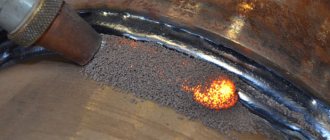
Features of the welding process and types of ES welding
The main difference here is the absence of an electric arc. All electrical energy is supplied to the slag, which is a conductor. Thanks to this reaction, the amount of heat required for melting is released. A special electrode is immersed in a prepared container with by-products. There is no arc burning here, but current continues to flow through the molten slag. It should be noted that these works have distinctive features:
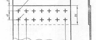
- the distance between the plates, which are in a vertical position;
- the active plane is not in contact with oxygen, since the entire area is covered with slag;
- electroslag welding is accompanied by low flux consumption, and the seam is alloyed with electrode wire;
- the alloy remains liquid for a long time, due to which excess gases evaporate from the composition.
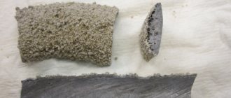
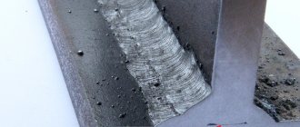
Welded joints made by electroslag welding
Also, the links are connected using a flat electrode. Cylindrical ones can also be used, but they will cause additional difficulties. More often, the seam is applied from top to bottom, and a gap is allowed between both objects. But for proper soldering, copper sliders with crystallization properties are placed in the empty gap.
Important point! The essence of electroslag welding is the melting and subsequent rapid cooling of sheets.
And if such manipulations are carried out in the open air, then cracks may appear on the surface. But the slag substance protects against such troubles.
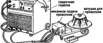
This technique makes it possible to fasten strips of unlimited thickness, however, the work is impossible to do at home. After all, the entire mechanism is large in size, and the methods of moving equipment for electroslag welding involve the operation of rail systems. And the main unit is the unit that feeds the wire into the connecting area.
As for additional subtleties, the heat emanating from the bath affects the areas adjacent to the seam. This happens due to strong temperature changes. Heat-affected zones are divided into several classes:
- Overheating. At this point, the grains of the base metal increase significantly.
- Area of complete recrystallization. Transformation phases occur here, but the heating is not enough for grain growth.
- The farthest zone. Here there is a decrease in the strength of the zone, which can be corrected by future heat treatment.
Yes, such automatic welding is impossible in a private household, but a person can acquire an electroslag smelter. It does not take up much space, is easy to use, and you can use anything you want for the raw materials: rusty pieces of iron, clean pieces of alloys, shavings, etc.
To use such a device correctly, you need to gain important knowledge. In particular, about the characteristics of rolled metal. For example, plates of increased thickness made of cast iron, titanium, copper, aluminum and their analogues are excellent for this procedure. However, this option is not suitable for soldering thin objects. As for use, it is easier to understand from sketches. A diagram of the entire electroslag welding process allows you to understand all the technology and features of the use of the unit.
The essence of the process
The essence of the technology is to transfer current to the slag, and from it to the electrode and the edges of the parts. The stability of the process is ensured by a constant temperature, which can reach 1900-2000 °C.
Most of the heat enters the weld pool, then the energy flows to the edges of the parts.
Basic schemes
The electroslag method is used not only for joining parts, but also for casting and surfacing. Welding is performed with consumable electrodes or nozzles, filler rods of large diameter. There are 6 main operating patterns that can be seen in the image.
It is worth considering the features of each option:
- The first 2 methods are considered the most common. They are used to connect workpieces with a height of 2-4.5 cm using an additive with a diameter of 3 mm.
- The third scheme can be used for welding more massive structures. The thickness of each part can reach 12 cm.
- The fourth option is characterized by high performance.
- The fifth scheme belongs to the category of narrowly focused methods. It is used when working with low-alloy steels. The leaf height can reach 10 cm.
- The sixth scheme is intended for creating dimensional structures without further heat treatment. The thickness of the welded workpieces can be up to 6 cm. The method helps to obtain a strong, uniform seam.
Welding process diagram.
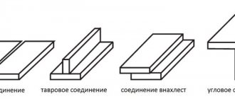
Types of Welds and Joints
ESW technology allows you to weld parts located in different spatial positions. The most commonly used types of seams are:
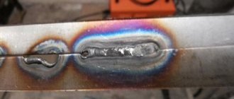
- Butt joints. A small distance is left between the parts, which is considered the main feature of electroslag technology. The procedure for cutting edges and forming welds is regulated by GOST 15164. When butt welding parts of different thicknesses, the thicker edge is thinned. It is possible to weld a metal plate to a less massive workpiece.
- T-joints and corner joints. They are used less frequently than butt ones. When using a melting tip, the weld edges are cut in a K- or V-shape.
- Straight connections. Performed in a vertical position. A slight tilt is allowed.
- Circular seams. Used when working with spherical or cylindrical workpieces.
We recommend reading: What types of welding exist?
EHS technology
It all starts with assembling the parts: two plates are installed at a certain distance from each other, special brackets are installed below and on both sides that secure the workpieces. Then a welding wire is placed in the empty gap and covered with flux (later it will melt, forming a solid base). After a certain amount of liquid slag accumulates, the arc is shunted by it and goes out. Further, electricity flows through by-products that have inflated resistance parameters. During the welding process, a high-temperature environment is created, which brings the iron to a molten state. Also, during the suture application, the satin surface goes through a cooling stage.
As the bath is raised, the fixing brackets are dismantled and an even and strong joint is formed. However, this is not the final stage, because you need to clean the finished seam, removing surface cracks and cavities. The technological strips that were installed at the beginning of the procedure are cut off with a grinder or other tool. Electroslag welding technology makes it possible to obtain a high-quality specimen that can be subjected to subsequent forging and stamping. It should be noted that the technique shows the highest efficiency in the design of ring joints.
Electroslag welding technology
Despite all the complexity, many enterprises actively practice this approach. The fact is that the resulting connection is of such high quality that it is similar to the main structure of the workpiece. With all this, there is no need for casting and forging of most parts. Also, electroslag welding is less expensive, and the diagram, in which all stages are clearly visible, is a direct confirmation of this.
Progress does not stand idle, and every year new techniques appear to solve difficult problems in the metallurgical industry. Improvements relate not only to the emergence of new devices, but also to the discovery of new materials. It should be noted that the priority of this “evolution” is automation and compactness of installations, as well as the manner of applying solders.
Important properties
Electroslag welding technology has many positive features and properties that are its advantages.
Among the main qualities it is worth highlighting:
- protection of the connection from exposure to atmospheric air. This function is performed by slag in liquid form;
- changes in current density during the welding process, unlike other welding methods, have little effect on the structure of the joint;
- During the process, there is a low short-term interruption of the current supply;
- You can make connections of any thickness at a time;
- You can weld raw edges of parts;
- there is a small energy consumption;
- low cost of consumables – slag;
- high efficiency is observed.
Important! During electroslag welding, not direct current is used, as with many other welding methods, but alternating current.
Welding methods
All actions are aimed at combining a narrow range of metals that fall under the class of low-carbon and medium-carbon. In exceptional cases, alloyed types are allowed. Also, all slabs must be of sufficient thickness. There are three types of modern electroslag welding:
- Using a continuous feed of filler electrode from left to right. The course of contact is reciprocating in nature, which gives a high density of interaction;
- With the use of flat contacts replacing slides made of copper material. This approach is accompanied by lower consumption of additives, but the electrodes must perfectly fit the shape of the workpiece;
- The third is a combination of the two previous types. There are two types of contacts involved here, where the flat one is fixed in place, and the melting one is fed into the active medium.
Multi-electrode electroslag welding
Electroslag surfacing with tape
Each type is used depending on the performance of the future item and the characteristics of the fused matter.
What fluxes are used?
Fluxes and slags for electroslag welding are one and the same. This substance is the leading one, and it must meet certain conditions:
- ensuring the start of the reaction in the shortest possible period of time and with any voltage;
- edge penetration at a high level;
- high attributes and strength of the finished seam;
- ease of cleaning up excess upon completion of actions.
Also, for each procedure you need to choose your own type of substance. For example, AN-8 is intended for low-alloy or carbon types of iron. Its calcination modes are 400-500 °C. The chemical composition of the granules includes oxides of silicon, manganese, calcium, magnesium, and aluminum. The weld metal will contain 0.12% phosphorus and 0.1% sulfur.
AN-22 is intended for high-alloy materials. This matter is similar to a glassy structure of yellow color. As for the calcination mode, it should reach 650-800 °C.
Flux for electroslag welding
When processing stainless steel, fluxes AN-45 and its analogues are used. However, when this substance melts, a large release of fluoride gases is observed, which is the main disadvantage. Technological properties are as follows:
- Good seam formation with a smooth transition to the base of the product.
- Low tendency to chip and crack formation.
- The grain size can be 0.25-3.0 mm.
- Satisfactory definition of the slag crust.
There are also less popular varieties. For example, AN-9, ANF-1, ANF-7. Each of the components differs in chemical composition, melting point and appearance, which must also comply with GOST.
Preparatory work
Welding begins with the selection of filler materials and equipment. After this, the parts are prepared for joining.
Selection of welding materials
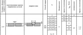
The types of wires used for ESW can be studied using the table:
| Type of steel | Filler material grade |
| Structural | SV-08A, SV-08GA |
| Medium carbon cast | SV-10G2S, SV-10G2 |
| Boiler room | SV-10G2S, SV-10G2 |
| Medium Carbon Forged | SV-10G2 |
| Low alloy | SV-10G2S, 18ХМА, SV-08-G2S, SV-08ХН2М |
| Medium alloyed | SV-08Х3Г2СМ, SV-20ХН3МФ |
| High alloy | SV-04Х19Н11М3 |
All materials presented in the table can be cooked using fluxes AN-99, AN-8. When joining steels 08Kh18N10T and 25KhN3MFA, grade 48-OF-6 material is used.
Mode selection
The main indicators are:
- current strength, I;
- reduction in voltage between the slag bath and the electrode, U;
- wire arrival speed, Vе;
- speed of electrode guidance, Vst;
- slag bath depth, h;
- wire extension, L;
- electrode oscillation speed, Vk;
- number of rods, n;
- electrode cross section.
Formula for calculating current strength
To calculate the current strength, use the formula I = (0.22Ve 90)n 1.2(Vst 0.48Vp)ab, where a and b are the height and width of the workpieces. The additive feed rate is: Vе= VсвF/S. Indicators Vk, L, h are constant.
Selecting the number of electrode wires
The parameter depends on the dimensions of the workpieces being welded. If the thickness does not exceed 5 cm, work with 1 wire. 2 electrodes are required when the parameter is 5-12 cm. When welding more massive elements, 3 wires are used.
We recommend reading: How to weld metals in a gas-protective environment
Preparation of products
Before starting work, the ends of the parts are cleaned of rust and oxide film. For this purpose, special grinding machines are used. The edges are given the desired shapes and sizes. It is recommended to install parts with a wedge-shaped gap that increases upward. The opening angle is selected taking into account the method of welding and fixing the workpieces. The indicator is most often 1-2°. The parts are secured with strips or brackets welded along the joint. After welding is completed, the fasteners are cut off using a gas plasma method.
Preparing the product for the welding process
The end of an object with dimensions no more than 20 cm is treated with a gas cutter. The need for this operation arises from the need to correct the ridges and hooks: they must be 0.2-0.3 cm, with a deviation from the right angle of no more than 0.4 cm. The surface of thicker metal products goes through a stage of mechanical action, and all rolled products are cleaned of oxides and corrosion using an emery machine. Casting and forging must be processed using a similar technique, and at a distance of 8 cm from the end.
If there is a need to connect two rolled products with different layers, then a stepped system of sliders is used, or the required layer is removed over the surface of a metal of greater thickness. When fastening ring-shaped alloys, the difference in the diameter of the joint should not be more than 0.5, and the shift should not be more than 1 mm. From the above we can conclude that such actions are of a jewelry nature. But there is another important point here: in order to get a high-quality part, all markings must be done with a slight indentation towards the larger side. This must be done due to the deformation that occurs during exposure to heat.
Preparing parts for assembly and welding
The suitability of parts for ESW is mainly determined by the cleanliness of the processing of the end surfaces of the edges being welded and the condition of the side surfaces of the edges along which the devices forming the seam will move.
For welding metal up to 200 mm thick, the end surfaces of the edges are prepared using gas-cutting machines. The size of individual combs and snatches should not exceed 2-3 mm, and the maximum deviation from the squareness of the cut should be no more than 4 mm. For metal thicknesses over 200 mm, as well as for circumferential welds and parts made of alloy steels, mechanical processing is used in most cases.
The side surfaces of parts made of rolled steel are usually cleaned of rust and scale using emery wheels. The side surfaces of cast and forged parts are machined to a width of 60-80 mm from the edge end with a cleanliness of R 80-R 40. In cases where stationary forming devices (water-cooled copper or welded steel) are used for welding, the side surfaces of cast parts are not processed.
When assembling butt joints of straight seams, the displacement of the edges (warping) should not exceed 2-3 mm. When welding parts of different thicknesses, before assembly, the thicker edge is cut off, or a leveling bar is installed on the thin edge along the entire length of the joint, which is cut off after welding. When welding parts of different thicknesses, special stepped sliders are used. Random displacements of the edges should not exceed 1-2 mm.
Tolerances for edge displacement are smaller for circumferential welds. The maximum difference in the diameters of the joined parts should not exceed ±0.5 mm, and the largest displacement of the edges during assembly should be no more than 1 mm. When welding circumferential seams of large-diameter cylindrical products with small wall thickness, rolled products without mechanical processing of the edges, the displacement of the edges should not exceed 3 mm.
When assembling for welding, plate washers with two round holes or other devices are usually used to reduce sheet deformation. These plates are passed into the gap between the sheets, and cylindrical wedges with a bevel are driven into the holes (≈40 mm in diameter).
Before welding, the assembly fixtures should be removed and replaced with fastening devices, which are most often staples welded to the back of the joint. For large thickness sheets, when the welding speed is low, instead of staples, plates can be used, welded with one-sided seams on the front side and removed during the welding process; fixing brackets or plates are installed after 500-800 mm. The plates are welded so that the seam ends 60-80 mm from the end surface of the edges.
To obtain the exact dimensions of the finished welded product, it is necessary to assemble parts with a gap that takes into account the deformation of the parts being connected during welding. It is necessary to distinguish between design, welding and assembly gaps. The welding gap is usually taken to be 1–12 mm larger than the calculated one.
In reality, the product is assembled with a large so-called assembly gap. The assembly gap at the bottom of the joint is equal to the welding gap. In the upper part of the joint, the assembly gap should be increased by 2-4 mm for each meter of joint length.
Electroslag welds are formed using water-cooled sliders or copper pads, as well as welded pads or locking joints.
To start the electroslag process and move it beyond the welded joint, an inlet pocket and outlet strips are used.
Excitation of the ES process
This reaction begins at the very beginning, when the flux melts in the bath and the entire zone is heated to operating temperature. Preparation also has a strong influence on quality.
There are two options for setting up a slag bath:
- solid start. Here, melting is carried out using an electric arc, followed by shunting and adding new slag;
- liquid start. Here, flux material in a liquid state is added to the workspace. It is pre-melted in an oven.
Using the first point requires more energy costs due to increased current. Also, ground powdered metal is poured into the bottom of the bar, which helps to produce a welding arc. Throughout the work, it is necessary to monitor consumables and add them periodically.
Download GOST 15164-78
Welding technology
The parts to be welded are installed vertically, leaving a sufficient gap between the edges. The formation of the weld metal is forced. A wire electrode or steel plate (rod) and flux are supplied to the welding zone. An arc burns between the wire and the metal at the beginning of the process. After a sufficient layer of liquid flux (slag bath) has formed, the arc goes out and the electric current passes only through the flux. The generated heat promotes further melting of the flux, wire electrode and edges of the materials being welded. The molten metal forms a weld pool by flowing to the bottom of the slag pool.
The welding head, together with copper mold sliders, moves along the parts to be joined from bottom to top, holding them. The sliders that form the weld metal are cooled through channels through which water circulates. The goal is to ensure normal formation of the seam and prevent leakage of liquid slag and metal from the melting space. As the gap fills, the slider plates move upward. The metal of the bath cools, crystallization occurs and a weld is formed along the entire height of the edges of the materials being joined.
Materials and equipment for ESD
One of the popular machines for this procedure is the A535. It is designed for single-pass ESP with alternating electricity. But this installation is suitable for limited electroslag welding.
It is important to add that the device will do an excellent job of soldering circular and longitudinal seams, the diameter of which will be no more than 300 mm.
Specifications:
- mains voltage – 380 V;
- current frequency – 50 Hz;
- number of rods – 3 pcs;
- wire diameter – 3 mm;
- metal thickness – up to 450 mm.
Electroslag welding machine A535
Other equipment - A550. Electroslag welding with its help follows a similar scenario, but here some of its parameters and properties differ . Some manufacturers offer to make a custom-made model, where its voltage will be 380 V, 415 V with a frequency of 50 Hz. You can also set the stroke height of the machine, depending on the size of the workpiece.
To improve the quality of the product, various additives can be added. They are also fed directly into the tank, where they are mixed with the main substance and help throughout the entire effect.
Equipment for electroslag welding
Automatic machines for this welding method differ in design and type of power source. Special devices move electrodes along the bath, which ensures uniform heating. The limiting side sliders and the mouthpiece with wire rise upward as the seam is formed. The design features are visible in the video. The stability of the process is ensured by power sources - three-phase transformers. Their use makes it possible to change the output voltage in the range of 38-54 V.
Three types of devices were developed in the USSR.
- Rail - moves along the seam along vertical guides.
- Trackless - attached to the workpiece mechanically and moved directly along it.
- Walking devices - move along the structure using electromagnets.
The use of a special melting mouthpiece made it possible to use ESW to produce seams of complex configuration. To form the required seam, the mouthpiece, which follows its shape, melts together with the wire.
Advantages and disadvantages of the ESW method
The leading positive feature of this effect is the ability to weld objects of enormous dimensions. The discovery of this technique made it easier to construct and repair massive objects. Other positive features of the electroslag welding process:
- the highest performance indicators when working with large plates;
- conservative consumption of electricity and auxiliary substances per 1 kg;
- excellent bonding quality, which is similar to the structure of the base material;
- there is no need to cut the edges, which greatly simplifies the preparatory work.
To the description of these characteristics, we can add that this method is more economical, and in theory it is possible to make a seam of any thickness in one pass.
Quality control
The appearance of defects deteriorates the quality of the welded joint, making it less durable. Special methods are designed to detect deficiencies.
How is quality control of welded joints carried out?
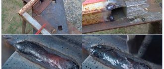
Characteristic defects
When working using ESW technology, welded joints may acquire the following disadvantages:
- Hot cracks. Occurs when working with any type of steel. However, high-carbon alloys are most susceptible to cracks. High welding speed with rigid fixation of parts also contributes to the appearance of defects.
- Cold cracks. Appear when connecting workpieces made of medium-alloy steels with a ferrite additive. Reducing the depth of the bath and uniform penetration of the joint help prevent the appearance of defects.
- Other defects. These include foreign inclusions, pores, and lack of penetration. Appear when welding rules are not followed.
We recommend reading Classification of the main types of fusion welding
Methods for controlling welds
Compounds obtained as a result of ESW require comprehensive research. The following control methods are used:
- visual inspection;
- ultrasound scanning;
- magnetic flaw detection;
- X-ray control;
- radiation flaw detection.
Ultrasound scanning of seams.
Application area
The field of application of any electroslag welding has a narrow range of specialization. It is most often used in the construction of large transport, for example, merchant ships. EBS also helps in the construction of massive bridges, where connection quality and strength play a vital role.
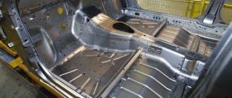
Electroslag welded structures
It is in this manner that the support die of a thick-sheet rolling mill is welded, the weight of which is more than 100 tons, and the cross-section is several square meters. During research and improvement, it turned out that ES welding can be used in various metallurgical manipulations: electroslag remelting. The difference here is that the current is supplied not to the wire, but to an electrode made of the material being melted. The molten substance itself accumulates in a container, which is cooled by circulating water.