§28. Armature windings
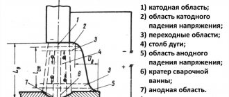
The principle of connecting individual conductors into a winding.
Modern DC machines use drum armatures, in which the winding conductors are placed in grooves on the outer surface of the cylindrical armature.
When making the winding, the conductors located in the grooves of the armature should be connected in such a way that e. d.s. formed in them. To do this, the two conductors forming a turn of the winding must be connected as shown in Fig. 92, a, that is, conductor A, located under the north pole, must be connected to conductor B, located under the south pole.
Rice. 92. The principle of winding a drum armature
The distance between the conductors making up the turn must be equal to or slightly different from the pole division m - the distance between the axes of adjacent poles. Under this condition, the turn will cover the entire magnetic flux of the pole and e. d.s arising in it when the armature rotates will have the greatest value.
For a visual representation of the windings, the cylindrical surface of the armature together with the winding is unfolded into a plane and all conductor connections are depicted as straight lines on the drawing plane (Fig. 92b).
The armature winding consists of separate sections. A section is the part of the winding located between two collector plates, following one after the other along the winding. The number of sections S in the winding is equal to the number of collector plates K. A section can consist of one or several turns connected in series. In the first case, the sections are called single-turn (Fig. 93, a, see Fig. 85, b), in the second - multi-turn (Fig. 93, b, see Fig. 85, a).
Rice. 93. Schemes of single-turn (a) and multi-turn (b) sections: 1 - active conductors; 2 — frontal part; 3 - active side; 4 - collector plates
Single-turn sections consist of two active conductors that directly cross the magnetic flux; active conductors are located in the grooves of the armature and are connected by frontal parts lying outside the armature core. Frontal parts in induced e. d.s. practically do not participate.
Multi-turn sections consist of two active sides, each of which combines several active conductors. Some high-power machines use anchor coils made of split sections (see Fig. 85, in §27). The armature winding, consisting of such sections, is called a rod winding.
In some cases, for design reasons and to reduce power losses in the armature winding, when manufacturing sections, instead of one solid conductor of the required cross-section, several conductors of a smaller cross-section are taken. These conductors are usually placed in a slot on top of each other and connected to the same collector plates.
All winding sections usually have the same number of turns. In winding diagrams, sections are always depicted as single-turn for simplicity. The winding section is placed in the grooves so that one of its active sides is in the top layer, and the other is in the bottom. In the diagrams, the sides of the sections located in the upper layer are shown with solid lines, and those in the lower layer with dashed lines.
When combining several sections into an anchor coil, each side of the anchor coil is in most cases placed in one common groove. In order for e. d.s, induced in individual sections, were added up; when connecting them, they are guided by the same rule as when connecting conductors into turns: the distance between the connected parts of the sections should be approximately equal to the distance between the axes of the poles.
Armature windings are divided into two main groups: loop (parallel) and wave (series).
Simple wave winding.
With a simple wave winding, sections lying under different poles are connected in series (Fig. 94).
Rice. 94. General view of the wave winding (a) and connection diagram of its sections (b)
In this case, after one round of the armature circle, i.e., after a sequential connection of p sections, they come to the collector plate located next to the original one.
For example, the beginning of section 1 is connected to the collector plate KP1, and its end is connected to the collector plate KP10 and the beginning of section 2, which is located under the next pair of poles; then the end of section 2 is connected to the other collector plate and to the beginning of the next section. After completing a full circuit of the armature circle, the end of the corresponding section is connected to the collector plate KP2 and the beginning of section 3, then in the same way with the collector plate KP11 and section 4, etc. until the winding is closed, i.e. will come to the beginning of section 1.
The anchor coil in the wave winding has the shape of a wave (Fig. 95, a), which is where it got its name.
Rice. 95. Shape of anchor coils with wave (a) and loop (b) windings: 1, 4 - groove parts (upper and lower sides); 2, 5 — rear and front frontal parts; 3 - rear head; 6 - ends of sections soldered to the collector
To make a winding, you need to know its resulting step y (see Fig. 94, b), the first y1 and second y2 partial steps, as well as the step along the collector uk. These steps are usually expressed in the number of sections passed (the step along the collector is expressed in the same units, since the number of collector plates is equal to the number of sections).
In a simple wave winding, the number of parallel branches of winding 2a is always equal to two and does not depend on the number of poles:
2a = 2 (56)
In Fig. 96, and as an example, a diagram of a simple wave winding of the armature of a four-pole machine having 19 sections, unfolded in a plane, is given, and in Fig. 96, b - equivalent diagram of this winding, showing the sequence of connecting its sections and the resulting parallel branches. The numbers 1, 2, 3, etc. indicate active conductors lying in the upper layer of each slot, and 1′, 2′, 3′, etc., in the lower layer.
Rice. 96. Schemes of a simple wave winding of a four-pole machine
With wave winding, only two brush fingers can be installed in the machine. However, this is done only in low-power machines; in more powerful machines, a full set (2p) of brush fingers is usually installed to reduce the current density under the brushes and improve current collection.
Simple loop winding.
With a simple loop winding, each section is connected to adjacent collector plates (Fig. 97).
Rice. 97. General view of the loop winding (a) and connection diagram of its sections (b)
For example, the beginning of the 1st section is connected to the collector plate KP1, and its end is connected to the adjacent collector plate KP2 and the beginning of the adjacent 2nd section. Next, the end of the 2nd section is connected to the next collector plate and to the beginning of the adjacent section, etc. until the winding is closed, i.e., until they come to the beginning of the 1st section. In this winding, each subsequent section is located next to the previous one, and the armature coil has the shape of a loop (Fig. 95, b), which is where the winding gets its name.
In a simple loop winding, the sections located under each pair of poles form two parallel branches, so the number of parallel branches throughout the entire winding 2a is equal to the number of poles 2p:
2a = 2p (56′)
Condition 2a = 2p expresses the main property of a simple loop winding: the greater the number of poles, the more parallel branches the winding has, therefore, the more brush fingers there should be in the machine.
In Fig. 98, and as an example, a diagram of a simple loop winding of the armature of a four-pole machine having 24 sections, unfolded in a plane, is given, and in Fig. 98, b - equivalent diagram of this winding, showing the sequence of connecting its sections and the resulting parallel branches (the designation of conductors and collector plates is the same as in Fig. 96).
Rice. 98. Schemes of the loop winding of a four-pole machine (UR - equalizing connections)
Application of loop and wave windings.
Each of the windings - loop and wave - has its own advantages. With the same number of conductors in the armature winding and the same number of poles, a simple loop winding will have p times more parallel branches than a wave winding. Consequently, it can pass a significantly larger current Iа = 2aiа than the wave winding (here Iа is the current in the parallel branch) (Fig. 99).
Rice. 99. Diagrams of parallel branches in a four-pole machine with loop (a) and wave (b) windings: 1 - collector plates; 2 - winding sections
The number of turns in each parallel branch with a loop winding is p times less than with a wave winding. Since the voltage of the machine is determined by the number of turns connected in series in each parallel branch, in a machine with a loop winding the voltage will be p times less than with a wave winding.
From the above it follows that in machines designed to operate at high voltages, it is advisable to use a wave winding. Such a winding is available in most auxiliary machines of electric locomotives and electric trains, which are designed to operate at a voltage of 1500-3000 V, and in some traction motors of electric trains.
In machines designed to operate at high currents, it is advisable to use a loop winding. Traction motors of electric and diesel locomotives, as well as electric locomotive excitation generators used for recuperation, have such a winding. Low power DC machines are usually made with two poles. With two poles, the loop and wave windings do not differ.
Equalizing connections.
In a simple loop winding e. d.s, induced in each parallel branch, is created by the magnetic flux of a certain pair of poles. E.m.f. E induced in all parallel branches of the winding should theoretically be equal (Fig. 100, a).
Rice. 100. E.m.f. induced in parallel branches of the armature winding with equality (a) and inequality (b) of the magnetic fluxes of individual poles
However, practically due to technological tolerances in the value of the air gap under different poles, casting defects in the core and other reasons, the magnetic fluxes of individual poles are somewhat different, as a result of which unequal e.m. operate in parallel branches. d.s.
If two parallel connected sources have unequal e.g. d.s. (Fig. 101), then some additional current will flow through the circuit formed by the two sources, due to the difference in e. d.s. E1-E2 sources.
Rice. 101. Occurrence of equalizing current with inequality e. d.s. two sources
This current is called equalizing current. The equalizing current Iur circulates inside the sources, does not do any useful work, but creates only losses of electrical energy in both sources. It causes uneven loading of individual sources, overloading the source with higher e. d.s. and unloading the source with less e. d.s.
In DC machines with inequality e. d.s. in separate parallel branches, the resulting equalizing currents will overload the brushes and impair the operation of the machines.
For example, with inequality e. d.s. E1 and E2 in the parallel branches of the armature winding 3 (Fig. 100, b) an equalizing current Iur will pass through the winding and through brushes 1 (A - D). The difference between e. d.s. E1 and E2 is 3-5%, but due to the small resistance of the armature winding, this is enough for quite significant equalizing currents to pass through the parallel branches, which contribute to the occurrence of sparking under the brushes.
In order for equalizing currents to be closed in addition to the brushes, equalizing connections are provided in the loop windings, which connect winding points that have theoretically equal potentials. Such points are the beginnings and ends of the armature winding conductors, located one from the other at a distance equal to double pole division 2t. The ideal would be to connect all such winding points. However, a large number of equalizing connections greatly increases the cost of the winding, so it is practically sufficient to have one or two equalizing connections for each group of sections lying in the same armature slot.
From a production point of view, it is convenient to connect equalizing connections to collector plates 2 (see Fig. 100, b). Usually they connect every third to fifth collector plate (Fig. 102).
Rice. 102. Scheme of making equalizing connections I, II, III in the loop winding.
The cross-sectional area of the wires used to make equalizing connections is 3-5 times less than the cross-sectional area of the armature winding conductors. Equalizing connections are most often located under the frontal parts of the armature winding next to the collector; in this case, they are outside the magnetic field of the main poles and no emission is induced in them. d.s.
Complex windings.
When the machine power is more than 1000 kW, complex multi-pass armature windings are used, which are several simple loop or wave windings wound on a common armature, offset relative to each other and connected to one collector. The use of multi-pass windings makes it possible to increase the number of parallel branches with a constant number of poles, an increase in which in some cases is impossible. However, these windings require complex equalization connections.
One type of complex winding is the parallel-series winding, used in some traction generators. It is a combination of simple loop 1 (Fig. 103, a) and multi-pass wave 2 windings.
Rice. 103. Diagram of a parallel-series winding (a), the location of its conductors in the grooves (b) and the shape of the armature coil (c)
Both windings are laid in the same slots and have common collector plates. For equality e. d.s. parallel branches formed by the loop and wave windings, the number of parallel branches of these windings must be the same.
The parallel-series winding is made in four layers (Fig. 103, b), since two two-layer windings are placed in the armature slots. This winding was called “frog” because of the shape of its anchor coil (Fig. 103, c). The winding in question does not require equalizing connections, which distinguishes it from other windings. The ability to reduce the voltage acting between adjacent collector plates by half compared to simple windings is an important advantage of parallel-series winding.
Contents Previous § Next4.7. Armature windings of DC machines
4.7.1. Features of the design of armature windings
The armature windings of DC machines are two-layer, in machines with a power of up to 30 - 40 kW they are made of round wire, in machines of higher power or for special purposes - from rectangular winding wire. The main element of the winding is a section that consists of one or more turns. A winding with single-turn sections is called a core winding. The output ends of each section are connected to the collector plates. Since each collector plate is connected to the beginning of one and the end of the second section, the number of collector plates K
equal to the number of sections
S
in the armature winding.
Several sections, the groove sides of which are placed in one layer of the groove and have a common body insulation, form a winding coil. The coil has as many pairs of output ends as there are sections it consists of. Examples of filling armature slots with conductors (sectional sides) and winding insulation from round and rectangular wires are shown in Fig. 4.25.
Armature windings can be loop or wave, simple or complex.
IN)
Rice. 4.25. Examples of filling the armature slots of DC machines with conductors
windings and insulation:
A
— semi-oval semi-closed groove, round wire winding;
b - rectangular open slot, winding made of rectangular wire (np = 3, ws
= 2);
c -
rectangular open groove, rod winding
(ip =
3,
ws =
1);
/ - body insulation; 2
- winding conductors;
3 -
spacer between layers;
4
— gasket under the wedge;
5 — groove wedge, b —
wire bandage; 7 — gasket for the bandage;
8 —
gasket for the bottom of the groove
Rice. 4.26. Designations of armature winding steps:
A
- loop;
b -
wave
They are characterized by two partial steps, a step along the collector and along the grooves (Fig. 4.26). Partial steps (first yv
the second
ang
and the resulting
y)
are measured in the so-called elementary grooves and have no equivalent in linear dimensions.
By elementary we mean a conditional groove in which one sectional side is located in each layer. Hence the number of elementary grooves of the armature z3 = S
=
K = zun,
where
un is
the number of sections in the armature coil.
The step along the collector uk
is measured by the number of collector divisions and determines the distance between the beginning and end of the section along the circumference of the collector.
The distance between the sides of the coil in the slot divisions of the armature determines the pitch of the winding along the slots ang.
The step along the grooves and the first partial step are related by the ratio ug
=
y\/ish.
In most windings!
/and„
is an integer.
In this case, the winding is equal-sectional. If yt/u„
is not an integer, then the winding is stepped. Step windings are avoided whenever possible due to the technological difficulties of their implementation.
4.7.2. Armature loop windings
IN
simple loop windings
y
=
yk = = ±
1 and
U = U1-U2 -
Windings with y, = + 1 are more widespread (Fig. 4.27),
since when yk = -
1, the frontal parts of the sections are somewhat lengthened and additional crossing occurs in the frontal parts of the winding.
The first partial step of the loop winding is close to the pole division: y1 = = z3/2p ± %,
where
\ is
a fraction in which
y1 is
an integer.
The value £
characterizes the shortening (lengthening) of the pitch
yt
compared to the pole division. Windings with shortened pitches are more common.
The loop winding requires the installation of brushes through each pole division, i.e. on 2p brush bolts. In this case, 2p parallel branches are formed in the winding. Thus, in a simple loop winding, the number of parallel branches is always equal to the number of poles, i.e. 2a
=
2r.
The asymmetry of the EMF and the resistance of parallel branches causes the possibility of the occurrence of equalizing currents, overloading the brush contacts and worsening switching.
Therefore, in armatures with loop windings of machines with 2p>2,
equalizing connections of the first kind must be installed.
In Fig. Figure 4.27 conventionally shows only two equalizing connections. On machine anchors, several connections are usually installed for each pair of poles or one connection for each armature slot. In high-power machines with difficult commutation, each section of the armature winding is connected by an equalizing connection. Structurally, equalizing connections are located under the frontal parts of the armature winding on the commutator side or on the side opposite to the commutator (Fig. 4.28). The installation of equalizing connections leads to a complication of the manufacturing process and an increase in the cost of the machine, therefore loop winding is used only in those machines in which a simple wave winding cannot be performed.
In machines with large rated armature currents, a complex loop winding is used to increase the number of parallel branches. Number of parallel branches in a complex loop winding 2a
= 2pm, and the step along the collector
uk - t,
where
t
is the number of winding strokes.
Depending on the K/t
a complex loop winding can be short-circuited or m-short-circuited.
In complex loop windings, it is necessary to install equalizing connections not only of the first, but also of the second kind, connecting points of theoretically equal potential belonging to different simple windings combined into a complex one.
Rice. 4.27. Scheme of a simple armature loop winding, z=
14,
K
= 42,
ia =
3
Rice. 4.28. Examples of constructive implementation of equalizing connections of the first kind:
A
- fork on the collector side;
b -
fork on the side opposite to the collector;
c -
ring; G
— involute;
/ - collector plates; 2 —
bandage of equalizing connections;
3
—
equalizing connections; 4 —
frontal parts of the armature winding; 5 — winding holder
ii |i li |ih |i I! |i |i ii |i |i |i |ii li Ii Ii Ii Ii Ii Ii Ii Ii Ii Ii Ii Ii Ii Ii Ii Ii
/ 2 3 H 5 6 7 S 9 10 tl 12 IS 14 IS 16 17 18 19 20
19\20\1 \2\3\q\S\6\7 \v\9\10\11\12\13\Ш15\16\17\16
Rice. 4.29. Scheme of a two-pass loop winding of the armature at Kip,
equal to an even number (k = 20, 2р = 4), with equalizing connections
In double-closed two-pass (t = 2) loop windings at K/p,
equal to an even number, points of theoretically equal potential are located on different sides of the armature. In a simplified diagram of such a winding (Fig. 4.29), equalizing connections of the second type are shown to the left of the diagram. In such machines, equalizing connections of the second type must be passed under the armature magnetic wire along the shaft or through the bushing (Fig. 4.30).
With K/r,
equal to an odd number, in two-way doubly closed loops
12J
Rice. 4.30. Location of equalizer connections of the second type at anchor: 1
— collector;
2
- equalizing connections of the first kind;
3 -
armature winding;
4
— armature magnetic circuit;
5
- equalizing connections of the second kind
On the left windings, equalizing connections of the first kind simultaneously serve as equalizing connections of the second kind, since they connect sections of different simple windings (Fig. 4.31). In the figure shown, two sections connected by equalizer connections are highlighted with thick lines. The same applies to two-way single-closed loop windings, since they always have K/p
equal to an integer.
4.7.3. Armature wave windings
IN
in machines with a rated armature current of no more than 500-600 A, wave windings have become more widespread (Fig. 4.32).
In simple wave windings y = y^+yr
and
2a = 2
, regardless of the number of poles of the machine. The advantages of simple wave windings are the absence of equalizing connections and the ability to operate the machine with an incomplete number of brush bolts. The latter winding feature is used, for example, in a number of traction motors due to limited space to accommodate a full set of (2p) brush bolts.
18
|
1
|
2
|
3 | 4 \S
|
6- | 7 | 8\9
|
?g| 11
|
/^ 173 \14 \i5\16\n
Fig. 4.31. Scheme of a two-pass loop winding of an armature at K/r,
equal to an odd number
with equalizing connections
Rice. 4.32. Scheme of a simple wave armature winding, z = 17, K=
51,
And"
= 3
Rice. 4.33. Schemes of wave asymmetrical windings of armatures:
a-winding with a “dead” section, g = 18, K=P,
2/> = 4; b - artificially closed winding, z=18,
*=18, 2р = 4
The step along the collector of a simple wave winding (Fig. 4.32) is equal to uk = (K
+ 1)
/р
(with the “+” sign, the winding is obtained with intersecting frontal parts, so the “-” sign in the formula is the main one).
If yk
is not equal to an integer, then the winding cannot be made symmetrical. In individual machines, for example, in widespread machines with 2p = 4, with even z or even CP, an asymmetrical wave winding with a “dead” section is sometimes made (Fig. 4.33, a). The collector is like this
machine contains one plate less than the number of elementary slots or the number of all sections in the winding. When K >
100 asymmetry in such machines has practically no effect.
When uk,
not equal to an integer, it is also possible to use an artificially closed wave winding (Fig. 4.33, b), in which the number of sections is one more than the numbers
z3
and
K.
The section of this winding, for which there is “no place” in the armature slots, degenerates into a connecting conductor , closing co-
Rice. 4.34. Scheme and sequence of laying a two-chord armature winding, r = 9, 2р = 2,
K=9:
a - winding diagram;
b -
sequence of laying turns in the grooves of the armature
end of the last section with the beginning of the first section of the winding.
In special-purpose machines, complex wave windings with t >
1. For them,
yay.
= (K +
t)/2r.
The number of parallel branches of a complex wave winding
is 2a ~ 2t.
In them, as well as in complex loop windings, it is necessary to install equalizing connections of the second type.
In a number of medium-power machines, to reduce the current in parallel branches and to avoid the need to install equalizing connections, a combined, so-called frog winding is used, the coils of which consist of sections of wave and loop windings and sections of both loop and wave windings are connected to each collector plate.
Thus, in the grooves of the armature there are, as it were, two independent windings - wave and loop. The number of parallel branches of these windings must be the same, so the wave winding must be complex. The number of parallel branches of the frog winding is 2 times greater than the loop winding for this machine.
Equalizing connections in combined windings are not required, since the wave winding sections play the role of equalizing connections for the loop winding, and the loop sections act as equalizing connections for the complex wave winding. Thanks to this, frog winding has become widespread despite the technological complexity of manufacturing its coils.
Laying conventional two-layer armature windings cannot be mechanized due to the need to raise the pitch at the final stage of this operation. Therefore, in anchors intended for mechanized laying, slightly modified circuits are used, for example, a two-chord winding (Fig. 4.34).
Contents Previous § Next