Transporting electrical energy over long distances inevitably leads to certain losses. In order to reduce losses, the transformation property is used in the transmission system. For this purpose, electric current passes through a transformer substation, which increases the amplitude of the voltage supplied to the power line for further transportation.
The end point of the power line is connected to the input of the remote substation. Here the voltage is reduced, after which the electricity is distributed among consumers. Both substations are equipped with power transformers, the design and operating principle of which makes it possible to convert high-power electricity. They differ in device features and technical characteristics.
Main parts and systems of power transformer
The metal casing is designed to house the electrical equipment of the transformer inside it. It is a sealed tank with a lid filled with transformer oil. This type of oil has high dielectric properties; it helps remove heat from parts subject to significant current loads.
The transformer is cooled using a hydraulic system.
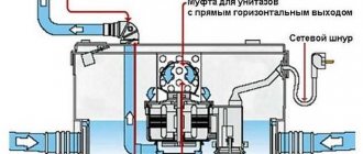
Filling and draining of oil is done using valves and screw-in plugs. Oil is sampled for chemical analysis through a shut-off valve located at the bottom of the tank. Oil circulation in a power transformer occurs through two circuits - external and internal. The external circuit includes a radiator consisting of upper and lower collectors connected to each other by metal tubes. The heated oil passes through the cooler lines, cools down and re-enters the tank. Inside the tank, oil can circulate naturally or forcibly under the influence of pressure created by pumps. Heat transfer is significantly improved due to special corrugations installed on the surface of the tank.
The most important element of a power transformer is its electrical circuit . All its elements are located inside the housing. The upper and lower beams make up the frame on which all other parts are attached. The circuit includes a magnetic core, high- and low-voltage windings, high-voltage and low-voltage taps, and control branches of the windings. At the bottom there are high and low voltage inputs.
Operating principle and operating modes
Power transformers operate on the same principle as conventional transformer devices. An electric current is supplied to the input winding, the oscillations of which vary over time. This leads to the induction of a changing magnetic field in the magnetic circuit. Next, the changing magnetic flux passes through the turns of the second winding, after which an electromotive force appears in it.
During checks and during operation, the transformer can operate in various modes:
- Work mode. In this case, the voltage source is connected to the primary winding, and the load is connected to the secondary winding. The current value in each winding must be no more than the permissible design value. This mode ensures stable and reliable power supply to consumers for a long time. In operating mode, open circuits and short circuits can be created in order to check the characteristics of the transformer device.
- Idling. It is created by opening the secondary circuit to prevent current from flowing through it. This mode allows you to determine the efficiency, transformation ratio, losses in steel parts spent on magnetizing the core.
- Short circuit mode. In this case, the terminals of the secondary winding are short-circuited. At the transformer input, the voltage is reduced to a value at which a secondary rated current with a constant value is created. This method allows you to determine losses in copper.
- Emergency mode. This includes any malfunction of the transformer that causes performance indicators to deviate beyond the permissible value. A particular danger is a short circuit that occurs inside the windings. To prevent the consequences of an emergency mode, automatic protection and alarm systems are installed in power transformers. They maintain the normal operation of the primary circuit and completely disable it in case of malfunctions and emergency situations.
Areas of application of power transformers
A power transformer is an electrical device, the main function of which is the conversion of electricity from the energy of one voltage value into energy that has a different purpose. Such transformers are divided into several groups:
- based on the number of phases, they are three-phase and single-phase;
- they have a different number of windings and are three-winding and two-winding;
- depending on where they are installed, they can be installed externally or internally;
- They are also different in purpose. Some are downward, while others are upward.
It is worth noting that these are not all the distinctions. Power transformers differ depending on the cooling method and based on the winding group.
Any transformer operates on the principle of electromagnetic induction. When the transformer winding is connected, an alternating current source is connected, it is through this winding that alternating current flows, and it creates an alternating magnetic flux in the magnetic circuit of the device. When this flux is closed in the magnetic circuit, a force is induced, which is called electromotive force. Moreover, this happens in a different winding. This suggests that all the windings of the device are interconnected by a connection called magnetic.
Such transformers have become simply irreplaceable in many areas. This area primarily includes industrial enterprises, as well as railway power lines. In short, the urban landscape of every city is necessarily complemented by power transformers.
Such transformers are created in order to transmit and distribute electrical energy. For this purpose, substations are built, which distribute energy between houses, factories, and factories.
There are converter transformers that are used to provide the required circuit for switching on valves in converter devices. In addition, they match the voltage at the input and output of this device.
Such power devices are also used for technological purposes. Thus, they are used in welding or as power supply for electrothermal installations.
They are also necessary to turn on electrical measuring instruments and some devices. This is necessary in order to expand the measurement limits in electromagnetic circuits and at the same time ensure electrical safety.
In addition, television and radio equipment also uses power transformers as power supply. Thanks to this device, it is possible to match the voltage and separate electrical circuits if necessary.
It is worth noting another important type of transformers - dry ones. They are designed to work in rooms that have a temperate climate, where the temperature can be from plus forty degrees to minus forty-five degrees, and air humidity is 75 percent even at fifteen degrees. Such transformers need to be installed no more than a thousand meters above sea level.
- TSZGL transformers are distinguished by the fact that they are without a casing, they have HV and LV terminals in order to be able to connect with flexible busbars or cables.
- TSZGL have a HV terminal inside the casing, but the LV terminals are either brought out to the roof of the transformer or are located inside the casing in order to be connected by cable.
- TSZGL and TSZGLF are created with NN type terminals; they are usually located on the side of the casing. At the same time, in TSZGL the HV terminals are connected inside the casing using a cable. But with TSZGLF they are brought out onto a flange in order to connect them with busbars.
For such transformers, special insulation windings are usually used, which have a quartz filler and fiberglass. This means that there is no possibility of cracks occurring even if the transformer is overloaded.
In order to transform electricity in power system networks, in order to block railways, power consumers of electricity, in order to power alarm equipment, there are single-phase transformers OM, OMP, OMG.
It is also important to say about the energy-saving transformers TMG 12. This is an oil-based device that is designed to convert energy in the networks of various energy systems, both for external and internal installation. Moreover, they are used at temperatures that range from minus forty-five to forty degrees. Due to the fact that energy resources are constantly becoming more expensive, it is advisable to save energy. This means that such an energy-saving transformer will come in handy. Another oil transformer is TMG 21. Thanks to it, it is possible to create a design in which current shocks and short circuits are reduced to a minimum. This is a dense structure that has increased resistance to radial forces.
Power transformers
Still have questions? ENERGOPUSK specialists will answer your questions: 8-800-700-11-54
(8-18, Mon-Tue)
Power transformer protection
First of all, it is necessary to constantly monitor the level of oil circulating inside the tank. Its temperature is influenced by a whole range of different factors. In this regard, there is a constant change in volume and the main task is to maintain the oil level within the established limits. An important role in this is played by the use of an expansion tank, which compensates for all volumetric deviations. In addition, it allows you to monitor the current oil level.
Data on the state of the level is taken using an oil indicator connected in parallel with the expansion tank.
Power transformers must be protected from moisture penetration, since the expansion tank with its upper part is in close contact with the environment. For this purpose, an air dryer is installed, which prevents moisture from entering the oil, which significantly reduces its dielectric properties.
An important component of the oil system is a gas relay that protects the transformer from internal damage. It is mounted inside a pipeline that connects the main and expansion tanks. During heating, the oil and organic insulation release gases that enter the gas relay container containing the sensitive element inside.
In some cases, an emergency increase in pressure inside the tank may occur. For protection purposes, an exhaust pipe is installed on the transformer cover. Its lower end must communicate with the tank capacity, and the oil must flow inside to the required level in the expander. The upper part of the pipe rises above the expander, which is moved to the side and slightly bent down. Its end is hermetically sealed with a glass safety membrane, which collapses in the event of an emergency increase in pressure.
Power transformers with a high-voltage winding over 1000 V are equipped with relay protection against major damage and malfunctions. Direct protective devices are secondary relays of direct or indirect action. They are connected not directly, but through voltage and current measuring transformers.
Installation and further operation of power transformers
Most power transformer designs are heavy. Therefore, special transport is used to transport them to the installation site. The equipment is supplied fully assembled and ready for connection.
Installation of the power transformer is carried out on a pre-prepared foundation or in a special room. To avoid air pockets under the tank cover during installation, steel plates are placed under the rollers on the expander side. Their thickness should provide a rise of 1% on the narrow side and 1.5% on the wide side of the transformer. The length of the gaskets is at least 150 mm. If the device weighs up to 2 tons, installation is carried out directly on the foundation. The housing must be connected to the grounding system.
Before installation, power transformers are tested in laboratory conditions. At this time, the transformation ratio is measured, the quality of connections, insulation, and the suitability of the transformer oil are checked.
Device and principle of operation
To understand how such a device works, you need to study its configuration. The power transformer device includes both main parts and additional parts.
Transformer device
The first include:
- Magnetic core;
- 2 or 3 windings;
- Expander;
- Frame;
- Entrances;
- Insulating elements.
The magnetic core is presented as a system made of electromechanical steel. This part of the power transformer device serves as the basis for fastening various parts. Windings are part of an electrical circuit. They are made of wire and insulation. The cable can be copper or aluminum. In terms of design, the windings are series coils. Their phases can be connected in two ways:
- in the form of a triangle;
- star.
The magnetic core with windings is located in a tank with mineral oil. This design is called a power transformer. It can be equipped with a radiator designed to remove heat. Some models of such devices also have protective systems in their design. Typically, equipment of this class is installed outdoors.
The operating principle of a power transformer is based on the physical law of electromagnetic induction. It is as follows. Connecting the device winding to the electrical network results in the formation of a magnetic flux. It induces an emf in another winding of the device. This principle of operation is explained by the presence of magnetic coupling in the device.