What is needed for work
A soldering gun, also called a hot-air soldering station, is a multi-component tool with a large number of functions for repairing modern devices. It allows you to solder SMD components, capacitors, LEDs and other parts. The same applies to BGA-type chips, which make installation more dense. Today, almost every electronic component in modern devices is made in this way.
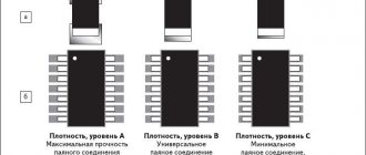
To solder SMD components, you need the following materials and devices:
- actually, the hair dryer itself;
- attachments for it;
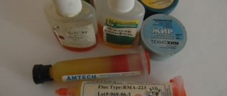
- flux with solder paste;
- copper braid;
- some kind of device for prying up parts (tweezers, for example);
- medium-soft brush;
- lens;
- a soldering iron with a thinner tip compared to a standard one;
- stencil for “rolling”.
To work competently with a soldering gun means to be careful, have angelic patience, and be extremely careful.
Necessary tool
Soldering iron
Old models
A properly selected soldering iron can ensure normal heating of the contact tracks of boards and semiconductor leads.
The old EPSI model of the “Moment” type with a power of 65 watts has a universal design. It is not difficult to make it with your own hands.
Previously, resistive type models with a heating element made of thin nichrome wire were widely used.
Modern soldering irons
For specific soldering conditions, you can now purchase various types of models equipped with all sorts of functions.
For example, a soldering iron with tin suction has been specially designed for soldering microcircuits, transistors and diodes.
It quickly heats up a layer of solidified solder and easily removes it in a liquid state from the contact pad.
Radio component holders
When heating the transistor leg for tinning and soldering, you should always remove the heat from the body and semiconductor layer with some metal object.
For this purpose, tweezers or alligator clips are usually used. However, it is most convenient to work with a medical instrument with thin legs, which surgeons use during operations.
Fixing electronic boards
Radio components and boards are usually small in size and require reliable fixation in space. Soldering them while hanging is dangerous: a small wrong movement can damage the entire structure.
When working with them, one hand is already occupied: it contains a soldering iron. And the second one needs to perform some additional actions. In this case, factory or homemade vices, holders, and clamps come to the rescue. They must be used.
Soldering needles
At the moment the solder melts, they are inserted inside the board sleeve to separate the leg of the radio component from the contact track.
A home craftsman can buy a ready-made kit in a store, for example, via the Internet in China or your city.
Medical syringe needles are well suited for the same purposes. Their tips need to be sharpened to a right angle.
Molten Tin Removal Tool
There are several ways to remove liquid solder from the melt site:
- shaking onto the floor, table or other surface;
- sweeping with a brush or brush;
- suction;
- absorption into a special braid.
The first two methods are extreme; they are used in extreme cases. For normal high-quality work, the last two methods are suitable.
Liquid tin suction method
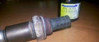
The tool adapted for it is called a tin pump. The appearance and design of one of the many models is shown in the picture.
Before work, the spring is cocked. When the solder is melted to a liquid state, the tip of the device is applied to it and by pressing a button, the force of the released spring is forced to move the piston to provide a vacuum, which draws the liquid metal into a special cavity.
Dismantling braid
It is made by weaving soft copper wire. Working with it is quite simple: a piece of braid is placed on the molten solder, and it quickly absorbs liquid tin.
Dismantling braid is sold in construction stores. An alternative can be a shielding core from an old coaxial cable for televisions, produced back in Soviet times. It is impregnated with a flux of alcohol and rosin.
Sequence of actions using the example of an SMD component
Let’s say that on the working printing surface of the electronic unit being repaired there is a burnt-out SMD box that needs to be dismantled. To remove it and install a new one, you need to select a compact nozzle for the hair dryer and prepare flux.
The temperature regime on the soldering hair dryer is set within 345-350 degrees using a regulator. Then they apply flux to the part to be replaced, and begin to slowly “warm up”.
The air pressure during the process should not be too strong, otherwise there is a risk of blowing away nearby elements. The culprit of the breakdown continues to be heated until the solder begins to melt, which will be immediately noticeable.
It may take about three minutes to warm up, and this is normal, there is no need to rush. If the solder persists for a long time, you need to add 5 degrees.
After the solder has liquefied, carefully dismantle the SMD part. During the process, it is important not to knock down the neighboring components, since they have probably lost stability due to the melting of the solder holding them in place.
Upon completion of the operation, the copper braid must be used to clean the “spots” (contact pads), then provide small bumps in the same places with solder paste or solder.
A serviceable smd is placed in the old place with a minimum amount of flux. Heat the part with a soldering hair dryer until the solder shines brightly, spreading over each of the contacts.
Features of working with BGA chips
When soldering BGA type microcircuits, the same temperature range is selected from 345 to 350 degrees, ensuring moderate air pressure to prevent blowing off the “neighbors”. During operation, the soldering gun should be held at an angle of 90 degrees with respect to the board. To avoid failure of the chip, you should not heat it only in the center; it is better to go around the mounting element around the perimeter.
After 1-3 minutes have elapsed, you can try to slightly lift the chip above the board using tweezers. If the chip does not budge, the solder is still hard. To avoid damage to the conductive paths of the board, you need to use the regulator on the hair dryer to “throw on top” 5 degrees of temperature and continue heating.
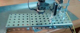
Heating from below
This technique is not only useful when working with a soldering gun, but also increases the convenience of soldering.
The board is secured with a clamp, the temperature is set to 200 degrees and warmed up for five minutes, after which they begin to work as usual.
Using thermal tape, you can shield nearby elements.
After removing the chip, the contacts are cleaned with the above braid. Do the same with the board.
All procedures must be carried out carefully to prevent damage to the circuit. If you don't have copper braid on hand, you can remove the solder using a soldering iron with a thin tip.
General idea of the soldering station
In general, the instruments under consideration are produced in various configurations and therefore the issue of choice is extremely important.
Stations conventionally presented on the market can be divided into two categories:
- contact;
- and, accordingly, contactless.
They also work on different principles. There are, in particular:
- induction (they are compact and quite powerful);
- hot air (a special hair dryer is used for soldering);
- infrared (intended for microcircuits);
- pulse (suitable for smartphones and tablet computers).
When we talk about contact stations, we actually mean a classic soldering iron equipped with a separate thermostat. They work in the same way as a regular tool, and no special skills are required.
In general, stations can be used not only for electronics, but also for other purposes. For example, they are convenient:
- remove old varnish from electrical wiring;
- dry glues;
- process plastic;
- heat the shrink insulation.
Regardless of the manufacturer, all stations equipped with a hot air gun are designed the same:
- the compressor supplies air directly to the heater;
- then it passes through the nozzle.
A set of additional attachments expands the functionality.
Professional stations have an accurate thermostat and reliable protection against overheating. Additional ease of use is provided by LED indicators or liquid crystal displays. The latter option is ideal for working with high-tech electronic components.
Reballing procedure
To carry out reballing, the chip is placed in a stencil and secured with specialized electrical tape. Apply solder paste on the back side with a finger or spatula, then set the hair dryer to a temperature of about 300 degrees and begin to warm it up. After the characteristic shine from the molten solder paste appears, allow the solder to cool completely.
To free the stencil from the chip, remove the electrical tape and heat the stencil to approximately 150 degrees; at the end of the procedure, the part should be free. It happens that it is impossible to immediately remove a part from a Chinese stencil, so it may be necessary to carefully hook it.
During reverse soldering of the microcircuits, the risks are assessed and the chip is laid out the required number of times to ensure an exact match of the heels and balls. Then they set the temperature on a soldering hair dryer to 330 to 350 degrees and heat until the melted solder allows the chip to fall into place on its own.
A soldering station is an indispensable tool for an electronics engineer. Usually the station comes with both a soldering iron and a hair dryer. If you learn how to use them, then almost any soldering will seem exciting and not very difficult.
A special feature of the stations is temperature control. You need to immediately remember an important rule - avoid temperatures above 400 °C or more. Many beginner (and even experienced) radio amateurs neglect this. These are critical values for microcircuits and boards.
Solder melts at approximately 180 to 230°C (lead-containing solders) or 180 to 250°C (lead-free). This is far from 400 °C. Why then set the temperature high?
Conclusion
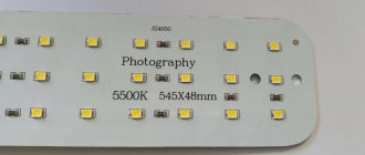
When soldering with solder paste and a hair dryer, a very good result is achieved in terms of heat removal from the crystal. And the more powerful the LED, the higher the efficiency of this technology
A 42g jar is enough for soldering approximately 50-100 LEDs.
on “Soldering LEDs onto solder paste with a hot air gun”
What is the temperature of the hairdryer? Were measurements of the light output of the light made before and after soldering? I use the same paste myself, but I do my lighting on 5730 and one-watt units. ps Is synth a second hobby?))) I messed up some chords a little)))
I also do it on single-padded sheets, so the light shines more evenly.
Thanks to the author for the article; if I had a thermal imager, I would have checked how heat is removed with hot-melt adhesive.
Hairdryer temperature 300-350C I didn’t check the light output before and after, but I didn’t notice any difference between those soldered by a hairdryer and a soldering iron.
Have you tried soldering on an iron?
No. I haven't tried it. Soldered with a Bosch construction hot air gun. Now I'm soldering with a hot air gun from a soldering station.
It seems to me that the problem will be to carefully remove the LED from the iron, since the solder there is liquid and with any awkward movement or deviation from the horizontal, the LED will slide off the pad along with the solder.
But it’s probably possible to adapt. Overheating will not overheat anything, since heating in any case continues until the solder paste turns into droplets of solder.
When soldering in this way, artifacts appear on some LEDs like this https://www.dropbox.com/sc/tf2f37amgjuc7vx/AAAvRS7LfDkoLVJxtRZIQJmUa It seems like I heat all the LEDs equally at 350 degrees. what could it be?
This has never happened before. Maybe some kind of special phosphor?
The image from the thermal imager was impressive - just a snapshot of a secret missile from a spy satellite. I’m looking at the radiator sprocket... There are 6 contact pads, half for plus, the other half for minus. Plus in the center. As I understand it, the central one is not for power supply at all, but solely for heat removal. There you can essentially just use thermal paste, right? This solder paste itself, with its electrical conductivity properties, is only needed on the plus and minus, right?
Read also: Best movie moments
The trick is to solder the central cooling pad of the LED housing to the sprocket. Since a soldered contact has thermal conductivity that is an order of magnitude less than that of any thermal paste. You can also solder the contacts with a regular soldering iron.
Hello, I tried to tin one such diode with a soldering iron from the side of the heat transfer pad, but the solder did not stick to it at all. It turns out that it is aluminum? How then does the paste stick to it? Or are there different types of substrates?
Shouldn't be aluminum. A friend of mine soldered pads with a soldering iron. Try soldering with some kind of flux
Hello, in this experiment the diodes are not on the radiator, but it would probably be smarter to stick them to the radiator, the contrast would be more noticeable, otherwise in the photo with cooling it is not at all clear why the middle diode is heated up more than the right one.
May be. Here, however, the heating is faster and the difference in temperature is more noticeable. I measured everything in this article. Both with and without a radiator.
please tell me where to buy such “stars” or what is their correct (full) name? Thank you
Link to Ali Keywords for search "20MM Aluminum Star PCB"
Alexey, is there a link to the “correct” diodes 660 and 445 on Aliexpress? I’m sure there are the right LEDs there, but I want to get a working version right away, and not go through a dozen sellers...
Unfortunately, I only bought such LEDs at TAO. On ALI I would choose a seller with a high rating and reviews and with an Epistar or Bridgelux chip.
Great, thanks for the extremely useful research! I am forced to add that not every flux is suitable for soldering aluminum; in your case - and of course, when making a product designed for a long service life - oxidation will inevitably occur. By the way, how to change the LED? Is it possible to unsolder it or are the properties of the paste such that it will not be possible to separate them without destroying the product? Thank you!
I came here through reviews on Ali, like a desert traveler to a blooming oasis. The site is a godsend! And phyto-lighting, and skillful hands and, most importantly, the miracle of the Cat (I had the same black cat)... In general, I dive in headfirst.
tell! and how to install LEDs on such star-shaped substrates on an aluminum plate, profile, etc. (to assemble a phytolamp, for example) I’m thinking of using hot-melt glue, but maybe there’s a cheaper option?
The “Sealant-gasket” for an engine produced in Kazan has good thermal conductivity. It does not lose its properties when heated and the LEDs do not fall off over time, as with some adhesives. It just doesn't dry very quickly
Lately I’ve been gluing “stars” and “stripes” on it, and sometimes even LEDs
Wow! Thank you I'll try
Excellent article, but there is some ambiguity in the text. Here the first of the three LEDs is soldered, and in the article about the thermal imager there is the same photo, but the first LED is no longer soldered, but only pressed to the sprocket. Where is the truth? I kind of guessed that it was not the LED itself that was soldered, but only its terminals, but it’s better to clarify this in the text and not use different captions for the same picture.
Sorry, stupid question: why heat the solder paste at all? Is it initially thick and should melt from heating and at the same time “glue” the LED to the board?
1. What exactly should you do if you don’t have a hot air gun? Is it possible to heat it somehow with a regular soldering iron - maybe through some kind of metal gasket? Or will you just burn the star?
2. Probably you shouldn’t trust the quality of Chinese thermal seals? I mean, buying lights and stars separately and then soldering them yourself with thermal paste is better than buying lights and stars thermo-soldered by the Chinese?
1. People solder using an iron or oven. The main thing is to heat it to the desired temperature and not overheat the LEDs. You can get used to soldering with a regular soldering iron - tin the heel of the LED and the central heat-dissipating path, then melt a drop of tin on it and quickly, before the tin hardens, apply the diode with tweezers. Check that it is firmly soldered with the same tweezers, then solder the pins
2. In mass production, soldering with solder paste is faster than with a soldering iron, therefore, for the most part there should be normal soldering. Although no one is 100% immune from the fact that the central nickel is not soldered at all. Just like the fact that the crystal itself in the case is normally soldered to the nickel. Operation will reveal all problems
No, I meant something else: is it possible to somehow solder with thermal paste and not tin using a soldering iron?
Yes, you can, but it’s not cost-effective. After heating, the solder paste turns into a drop of solder. And it costs much more than solder.
Those. solder paste, not thermal paste - I misspoke.
Educational program for beginners
To desolder a part from a board, you need to make sure that the contacts are heated until the solder melts (approximately 230 °C). The main mistake beginners make is to immediately heat the place where they are soldering to 300 - 350 °C.
For example, you need to desolder a microcircuit from a board using a Lukey 702 soldering station.
Many radio amateurs and electronics engineers set heating parameters above 300 °C.
At the first moment, the part is exposed to about 200 °C. The contacts and the surrounding area of soldering work are at room temperature.
The heating of the part reaches 300 °C, but the contacts have not yet reached 200 °C.
The microcircuit experiences a critical temperature of 350 °C. Meanwhile, the surrounding soldering area is heated unevenly, even if the hair dryer is evenly moved across the soldering area. A noticeable temperature difference appears at the contacts of the part.
400 °C and the microcircuit begins to fry.
A little more, and it will unsolder due to the fact that the contacts have practically heated up until the solder melts. But this happens because the board has warmed up. And in this case, it happened unevenly. High temperatures lead to thermal breakdown of the microcircuit and it fails. The board bends, turns black, and bubbles appear due to boiled PCB and its components.
This soldering method is very dangerous and ineffective.
How to desolder a microcircuit
How do you solder parts without damage?
It is necessary to analyze the soldering area and equipment:
- Estimate the thickness of the board. The thicker the board, the more difficult and longer it takes to warm it up. The board consists of layers of tracks, masks, pads and many metal parts that are very heat-intensive.
- What's nearby? To avoid damaging surrounding components, they must be protected from temperature. The following will cope with this task: thermal tape, aluminum tape, radiators and coins.
- What is the ambient temperature ? If the air is cold, the board will have to be heated a little longer. Of particular importance is what is located under the board. No need to solder on a metal plate or on an empty bench. A wooden board or a set of napkins works best. And at the same time, the board must be in the same plane, without distortions.
- Equipment. Many soldering stations are sold without calibration. The difference between the temperature shown on the indicator and the actual temperature can reach either 10 °C or 50 °C.
How to solder with a hairdryer correctly
It is necessary to cover all small components that are vulnerable to overheating with protection.
In this case, aluminum tape is used. It protects components well from temperature and holds the board components tightly. However, it adds heat capacity to the soldering area. Thermal tape also protects well, but sticks to the board less well.
The board is placed on a material that has the least heat capacity and slowly releases temperature to the environment. You can use, for example, a wooden plank. And at the same time, the soldering area should not be inclined.
It is best to apply flux to the contacts. It distributes heat well compared to heated air, but you should not add too much of it. It may boil, hiss, or interfere with soldering.
The first step is to warm up the soldering area. The hair dryer is set to about 100 °C and maximum air flow.
It is necessary to warm up both the part itself and the surrounding soldering area with contacts in a circular motion.
Next, after about a minute, you should gradually increase the heating.
The difference with the contacts will be small. Thus, within a few minutes, increase to 300 °C.
Steps of about 20 - 30 °C for every tens of seconds.
Peculiarities
The soldering procedure with a construction hair dryer is associated with a large expenditure of energy resources, because the heater power sometimes reaches 2.5 kW. This contributes to high productivity - 300-400 l/min. The flow of heated air masses affects a large area, which is sometimes inconvenient when it is necessary to influence a specific point. In this regard, plastic welding with a hair dryer is carried out using quick soldering nozzles, which make it possible to supply filler material directly to the joint area.
How to understand that a part is already soldered
A glare appears on the contacts. Using tweezers, gently push the chip. If it moves easily and smoothly from side to side, then it can already be removed; if not, we heat it further.
This technique must be individually adjusted for each soldering and soldering station. For example, sometimes you will have to heat the board longer, and sometimes about 240 °C will be enough. The soldering method depends on the case.
How to change the heating element
The quality of work largely depends on the condition of the heating element. In particular, it must be replaced regularly. Carry out all work only after the tool has completely cooled down.
The procedure is as follows:
- unscrew the handle lock nut;
- remove the cap;
- pull out the sting;
- take out the grounding spring;
- remove the heater and the wires leading to it (the latter are disconnected from the terminal);
- install a new element, being careful not to damage the grounding;
- collect the pen.
Alloy Rose
To reduce the risk of overheating, Rose alloy can be used. It will help reduce heat to 120 °C. In this way, you can remove the part from dangerous and sensitive areas. Just add a couple of solder granules and a little flux.
After tinning the contacts, the part is easily desoldered. You need to carefully desolder the contacts; they can easily be damaged due to sudden movement.
The resulting solder must be removed from the board. It is very fragile and not suitable for use.
Combined method
Another very effective technique. If during soldering the part is poorly soldered or does not desolder, this is a consequence of low-quality solder, flux, or insufficient heating of the board.
To do this, while working with a soldering iron, you need to help from above with a soldering hair dryer. The hair dryer should be set to 200°C. This way, heating will occur faster, and the temperature at the contacts will stabilize, and the surrounding air will absorb less heat.
Factory soldering
In the factory, other soldering technologies are used that allow several boards to be soldered simultaneously. A special robot installs the necessary elements on the base, on the working side of which solder paste is applied using silk-screen printing. It contains solder and flux; when heated, they change phase and perform their tasks. The flux degreases the contacts and provides wetting, and the solder, under the action of capillary effect, flows into the gaps of the connections and ensures a strong connection of the SMD elements.
The process takes place in a special oven, where the board is kept for a certain time. The contact duration and heating mode are selected in such a way as not to harm SMD LEDs. The procedure occurs quite quickly and ensures soldering of elements in industrial quantities.
Important! It will not be possible to repeat this technology at home, since you need to have a full set of equipment and materials. Therefore, it is important for hobbyists to master the process of manual soldering of SMD LEDs using conventional tools and materials.
In what cases will soldering with a hairdryer not work?
A soldering gun usually reaches a power of no more than 500 W. The lower the power, the less the board area can be heated.
A massive board requires bottom heating. Most often this is a stove that heats up to 100 - 200 °C. The printed circuit board will be heated evenly. And use a hair dryer to bring the solder to melt.
You can also use a hair dryer. It has a larger nozzle and its power can be up to 3000 watts. However, a hair dryer is not a solution either. Due to the fact that only the part and a small surrounding space around it are heated, after soldering the board is deformed due to the high heating difference, thereby tearing off the leads from the pads (this is especially true for large BGA parts).
The need to dismantle radio elements arises in several cases:
- Dismantling the faulty element;
- Incorrect installation of the radio component;
- Soldering from the donor board due to the lack of a new microcircuit.
In all these cases, except for the first, the main conditions are maintaining the integrity and working condition of the soldered part and the integrity of the printed circuit board.
To carry out this work, it is necessary to observe accuracy and simple rules that were developed back when most of the range of radio components was in short supply. The urgent question was how to remove an expensive microcircuit from the board without damaging it.
All about soldering plastic with a hairdryer
A construction hair dryer (or hot air gun) is a popular tool when carrying out various repair work. Its capabilities include drying, soldering, welding, cutting and bending material. But the potential for its application is much broader. A resourceful person can come up with a lot of possibilities for using this tool, since a modern hot air gun for welding plastic makes it possible to carry out work of varying complexity in a short period of time. Even inexpensive samples can help carry out simple repairs of PVC pipes in a home, not to mention specialized construction (technical, industrial) devices designed to perform large-scale work.
Chip types
The wide variety of microcircuit packages has led to the fact that soldering techniques began to differ. Previously, the most widespread were microcircuits with pin pins for mounting into holes on a printed circuit board. Subsequently, with an increase in the degree of integration and the widespread use of automated soldering lines, surface mount elements with flat or ball leads began to be used.
ICs (integrated circuits) with solder pins are typically DIP and SIP packages with two and one row of pins, respectively.
Surface mounting ( SMD ) allows installation of ICs with pins of the following types:
- Flat leads brought outside the housing - SOIC, SOP, QFP (square housing);
- Flat legs, bent inward, under the body - SOJ, PLCC, QFJ;
- Ball terminals - BGA.
Each variety has several subspecies. The total number of housing types is in the dozens.
Safe work with semiconductor radio components
Before you unsolder a part from the board with a soldering iron, you need to know the following. Semiconductor elements are extremely sensitive to overheating. Also, tracks on a printed circuit board at high temperatures or when the soldering time is exceeded can peel off from the substrate or break, which is even worse.
Temperature conditions
The temperature of the soldering iron tip should be 200-250⁰С. At higher temperatures, peeling of the printed tracks and overheating of the microcircuit may occur. The same goals are set for the soldering time of one leg - no more than 3 seconds.
Note! Some sites advise for dismantling to focus not on the temperature, but on the power of the soldering iron. It is not right. Their temperatures are the same, it’s just that a less powerful one may not be able to cope with melting the solder at the pin due to intense heat removal, and a too powerful one can easily overheat the pins and the board. The best option is a 40 W soldering iron.
Many microcircuits are sensitive to static electricity. It is necessary to work with an electrostatic wrist strap on and a grounded tool.
Wiring of planar parts
So, how does the process itself work? Read something here. We bite off small pieces of Rose or Wood solder (alloy). We apply our flux liberally to all contacts of the microcircuit. We put a drop of solder on Rose, on both sides of the microcircuit, where the contacts are located. We turn on the soldering iron and set it using a dimmer, the power is approximately 30-35 watts, I don’t recommend it anymore, there is a risk of overheating the microcircuit during dismantling. We pass the tip of a heated soldering iron along all the legs of the microcircuit, on both sides.
Dismantling using Rose alloy
In this case, the contacts of the microcircuit will close, but this is not scary, after we dismantle the microcircuit, we can easily remove excess solder from the contacts on the board and from the contacts on the microcircuit using the dismantling braid.
So, we took hold of our microcircuit with tweezers, along the edges, where the legs are missing. Typically, the length of the microcircuit, where we hold it with tweezers, allows us to simultaneously move the soldering iron tip between the tips of the tweezers, alternately on both sides of the microcircuit, where the contacts are located, and slightly pull it up with tweezers. Due to the fact that when melting Rose or Wood alloy, which have a very low melting point (about 100 degrees), relative to lead-free solder, and even ordinary POS-61, and moving with the solder on the contacts, it thereby reduces the overall melting temperature of the solder .
Board design
Printed circuit boards differ in the number of printed layers and the method of installing radio components:
- Single layer;
- Double layer;
- Multilayer;
- For DIP elements;
- For SMD components.
One board can contain both DIP and SMD elements on one or both sides. Multilayer printed circuit boards, in addition to outer layers, have internal ones, which usually serve for general shielding or wiring of power circuits. Thus, the motherboards of modern computers or mobile phones have up to seven layers.
Dismantling techniques
The method of soldering microcircuits depends mainly on the type of pins, although there are universal methods.
Dismantling the microcircuit with a soldering iron
This is the most time-consuming and unreliable method. It is used only when the number of microcircuit legs is minimal. Before soldering microcircuits with a soldering iron, the tip of the tip is carefully tinned and cleaned of solder residues so that it remains only in the form of a thin film. The molten solder that surrounds the IC leg is transferred to the tip under the action of tension. By repeating the procedure several times, the leads are completely released.
Important! Before each touch of the board, the tip is cleared of solder. The touch time should not be more than three seconds. If the leg is not completely freed, you can only work on it after some time has cooled down. At this time, you can make the following conclusions.
Removing the chip using a razor blade
When working with planar elements, an ordinary razor blade will come to the rescue. For convenience, the razor blade is broken in half lengthwise. Leaning the blade close to the border of the terminal and the board, heat the scion until it melts. By inserting a blade between the leg and the board, they are separated. The blade is made of stainless steel, so solder does not stick to it.
Using dismantling braid
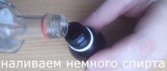
The special dismantling braid works thanks to the capillary effect, drawing in the molten material. You can use braided shielded cable with the same effect. The braid must be clean, without traces of oxidation. In order to improve the spreading of the melt, the braid is moistened with liquid flux.
Dismantling microcircuits using a desoldering pump
The desalination pump is a special piston that, when moving, draws in the melt, releasing the outlet. This method is suitable for working with DIP and SIP components.
Using medical needles
This method has proven to work best when dismantling ICs, especially for single-sided printed material. Double sided PCB can also be used to remove needles from syringes. When choosing a needle, you need to ensure that its inner diameter allows the leg of the microcircuit to fit freely, and its outer diameter allows it to fit into the hole on the printed circuit board. The tip of the needle is ground with a file until a smooth surface is obtained.
The needle is placed on the tip of the leg and the terminal is heated with a soldering iron. After the solder has melted, the needle is inserted into the hole of the board and smoothly rotated around the axis until the tin solidifies. After this, the needle is removed from the stem, which is now completely free. The needle material (stainless steel) is not tinned, so rotation around the stem is only necessary to make it easier to remove it from the hole.
Use of alloy rose
Using a rose alloy, you can desolder all the terminals of the IC at the same time, due to the fact that the low-melting alloy spreads between the terminals and evenly and simultaneously transfers heat to all of them from the heated soldering iron tip. After complete heating, the part is carefully removed from the board using tweezers.
This method has one disadvantage - after dismantling, it will not be possible to collect the remaining rose alloy, since it will be clogged with excess tin and lead, which will change its composition and melting point.
How to desolder a microcircuit from a board with a hairdryer
When working with SOJ, PLCC, QFJ and BGA packages, a soldering station or hair dryer with temperature control is required. Using the station, the entire section of the board is heated until the microcircuit is released, and using a hair dryer with a nozzle, a stream of hot air is directed to the terminals of the IC until they are released.
Radioelements must be desoldered at a temperature of 250⁰C. To prevent overheating, adjacent elements should be covered with aluminum foil.
How to remove capacitors from a motherboard
To desolder capacitors or other two-terminal elements, there is no need to use a special soldering tool. During the dismantling process, one of the terminals of the capacitor is heated, while simultaneously tilting the element so that the leg comes out of the hole. Next, repeat the same with the second leg, tilting the part in the opposite direction. To avoid tearing, do not press hard on the capacitor. By warming up both terminals in turn, they are gradually released.
Air soldering iron
In some cases, an air soldering iron comes to the rescue. It is named so because the heating of the leads of the parts is carried out contactlessly, using air heated to a high temperature.
It’s easy to make such a hot-air tool with your own hands, using a regular soldering iron as the starting material. To do this, some changes will have to be made in its design.
The soldering iron tip, which is heated by an electric element, must be replaced with a steel tube of a suitable diameter. It is placed inside the element and must pass through the handle of the tool.
Air should be supplied under slight pressure from the side of the handle. If you use a polyethylene tube and a low-power compressor for aquariums for this, you can get a simple air soldering station. The air temperature can be changed with a voltage regulator.
A hot-air soldering iron can be used for mounting and dismantling SMD components, which are very small-sized elements and are not inserted into the holes of circuit boards, as is customary with traditional parts, but are mounted directly on the contact tracks.