Let's get started
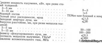
5 atmospheres, gas - 0.5
After this, you need to take a propane cutter and open the propane slightly, and then set it on fire. The cutter nozzle must be positioned so that it rests on the metal, after which you need to slowly open the oxygen control. Next, you should adjust these valves one by one, thereby ensuring the required flame supply force. During such a setup, you need to sequentially open gas, oxygen, gas, oxygen.
When choosing the flame strength, you need to focus on the thickness of the metal. As the thickness of the sheet increases, the strength of the flame will have to increase, which will lead to an increase in the consumption of oxygen and propane. After adjusting the flame strength, you can start cutting metal. The nozzle must be held in relation to the edge of the metal so that it is removed from the object being cut at a distance of 5 mm, and it itself must be located at an angle of 90 degrees. In some cases, it may be necessary to cut through the sheet or product in the center. In this case, the starting point is chosen to be the place from which the cut will go.
The essence of the procedure is to heat the top edge to a temperature of 1000-1300 degrees Celsius. The exact temperature is determined taking into account the metal. In practice, such work will look like the surface appears to be “wet.” The heating itself will take no more than 10 seconds. After waiting for the metal to ignite, you need to open the cutting oxygen valve, after which a powerful, narrowly directed jet will begin to flow.
Cutting Features
eliminate the risk of kickback
First, it is maintained at 90 degrees, after which it is necessary to create a slight deviation of 5-6 degrees in the direction opposite to the movement of the cutter. If you have to deal with metal whose thickness is more than 95 mm, then it is allowed to increase the deviation to 70 degrees. After the cut in the metal reaches 15-20 mm, the angle of inclination begins to increase to 20-30 degrees.
Popular services on the market
If you need to cut metal, the easiest way is to hire a craftsman or specialist who will provide you with the necessary services. After all, not every home has a cutter with two cylinders of oxygen and a heater in the garage.
Moreover, working with such equipment is very dangerous without experience! If you don’t know how, then it’s better not to take on this matter - entrust the work to professionals!
For example, conventional sheet cutting is the cheapest. Pipe cutting costs much more, since this type of work uses additional pads!
But depth cutting is an expensive pleasure, since it uses expensive equipment.
IMPORTANT TO KNOW: Longitudinal cutting of metal - machines, lines, units
Moreover, if such work is carried out “on site”, it will be very expensive. Vehicles that can transport cutting stations must be additionally re-equipped.
Oxygen cutting of metal - video:
Well, gas cutting of sheet metal can be done even with an ordinary gas soldering iron. If you are using aluminum or copper, it should be sufficient for the job.
In some cases, gas welding can be used. But instead of carbon dioxide, propane, acetylene or butylene is supplied (not every gas welding supports the use of such gas, be careful)!
By the way, if you need to perform cutting rather than cutting, then in some cases it will be much easier and cheaper to use a knife for cutting metal rather than a gas cutter. You can find out more about this directly from the master you want to entrust with the work.
Nowadays, many enterprises offer on-site gas cutting of metal.
Here it is, assessed according to the following parameters:
- metal with which it will be necessary to work;
- difficulty of performing the work;
- cutter used.
By the way, it is recommended to buy gas cylinders yourself! Many companies sell it at too high a price (about 1,000 rubles for an acetylene cylinder, although its market value is about 400 rubles).
It also takes into account how long the work will take. On average, an hour of work by a master is paid approximately 300 rubles. Now you can calculate in advance how much metal cutting services will cost you!
And finally, we should talk about those cases when poor quality work is performed. Very often, many people use propane or propylene instead of acetylene - its cheap analogue. Or they use cheaper cutters than they advertised.
The P1-01 model has a double nozzle with a gold mount (golden color), while the P2-01 has a steel mount (black or copper tint).
By the way, the P1-01 cutter is not that expensive, so you can even buy it! The average cost is between 900-1000 rubles per piece. Well, of course, you will need to purchase two cylinders - with oxygen and a heater, and a transport cart.
On average, the whole set will cost you 3,000 rubles, no more. It will be enough for 3 hours of metal cutting. For household needs this is more than enough.
And when working with a gas cutter, be sure to follow safety rules! And this is the use of a protective mask, overalls and gloves. Gloves are a must!
Purpose of oxygen cutting of metal
According to its purpose, oxygen cutting is divided into surface and separation.
Separation cutting includes the manufacture of blanks, cutting of metal sheets and other work associated with the division of an initially integral metal into several separate parts.
Surface cutting includes:
- removal of defects from castings,
- rolled products and welds,
- cutting grooves on metal,
- removal of the surface layer from metal and a number of other works.
According to the method of execution, oxygen cutting of metal is divided into machine and manual. Manual cutting is performed using a special cutter, and machine cutting is performed using special gas-cutting automatic and semi-automatic machines.
Gas cutting technology
Modern technology for gas cutting of metal is somewhat different from that described above. For example, when working with “light metals,” temperatures of 1000 degrees Celsius and higher can simply destroy the metal you are working with (melt and evaporate).
In these cases, the cutting itself is performed with simultaneous heating. The cutting torch tip has a pyramid shape with 3 nozzles.
A heating mixture is supplied through two side ones, and a thin nozzle is mounted in the center to supply oxygen under high pressure.
Oxygen cutting technology
In modern cutters, oxygen is supplied under pressure of 12 atmospheres! Simply put, even skin can be damaged under a stream of air (meaning an unlit stream).
The flux that is formed during such cutting is either thrown out to the sides by a heating flame, or is burned directly through the entire metal (if through cutting is performed).
Do not forget that cutting metal with gas has a great advantage over electric cutting. Which?
But keep in mind that cutting metal with oxygen does not mean using metals that melt at temperatures below 600 degrees Celsius. In this case, simple removal of the top layer of metal will be performed, rather than cutting it.
In such cases, it is recommended to use so-called mobile heaters - ordinary cans with compressed gas and a nozzle at the end of the tube.
Standard oxyfuel metal cutting technology involves the use of a guide cutter that is controlled by the operator. The gas supply is regulated using two valves (in some models - one common).
Cutting torch
The cutter handle itself has two tubes, which are built into the handle. The first handle supplies fuel for the heater, the second (usually the central one) supplies oxygen. That is, as many as 3 tubes are connected to the main nozzle!
What is the gas consumption when cutting metal? This depends on the temperature to which the metal itself is heated during operation.
In a standard P1-01 cutter, in one hour of operation, on average, about 10 cubic meters of oxygen and 0.7 cubic meters of acetylene are consumed (when using propane - 1 cubic meter of fuel).
Video:
But in the R2-01 cutter the consumption is much higher - 21 m3 of oxygen and 1.2 m3 of acetylene! The heater consumption depends on the heating temperature and the plane that is cut.
“Older” cutters also use the so-called direction of the nozzles, which also partially affects the flow rate (the closer to the oxygen stream, the larger the jet has to be supplied).
Basic rules for cutting thick metal with gas
Oxygen gas cutting is used for cutting steel alloys with a thickness of 0.5 to 6 cm. Due to the oxidation reaction, heat is released, which heats and melts the metal. And the products formed due to the combustion of the material are removed from the cutting zone by gas flows.
There are a number of requirements that must be observed in the process of preparing and performing oxy-fuel cutting of materials:
- Before starting work, it is necessary to carefully clean the surface along the future cutting line to a distance of 10–15 cm. Residues of old paint, lubricants, and oil and fat films must be removed. If left, fire and sometimes explosion may occur during gas cutting. In addition to them, it is necessary to get rid of rust, since its presence slows down work due to the thermal insulation properties of the latter.
- There should be free space at the bottom of the workpiece for the gas stream to escape. Its size is small - 5–10 cm. However, its absence can lead to turbulence in the gas flow due to its reflection, which is extremely undesirable, and also negatively affects the speed of work, and also causes thermal deformation of the product.
- The angle of deflection of the cutter from the vertical should not exceed 5°. Otherwise, the shape of the torch is distorted, accuracy decreases, and the quality of the cut surface deteriorates.
- To perform the work, a welder needs high qualifications and sufficient experience. Fulfillment of this requirement will guarantee high productivity and cutting accuracy.
Gas is supplied to the cutting zone using shut-off valves: one common and two shut-off valves. Using two different shut-off valves helps you quickly control the mixture and reconfigure your gas cutting equipment.
There are three nozzles with connectors on the cutter handle. It is with their help that gas for welding and cutting metal enters the cutting zone: acetylene or propane, oxygen, as well as cooling liquid. The gas pressure when cutting metal is set on the cylinder reducer. It should be ≤ 12 atm.
Types of metal cutting with gas
For example, if it is possible to connect to the network, then you can use oxygen-electric arc cutting, or when working with low-carbon steels it is better to use a gas-air mixture with propane. The following methods are most in demand in practice:
- Propane cutting. Metal cutting with propane and oxygen is one of the most popular methods of work, but it has some limitations. The operation is feasible for titanium alloys, low-carbon and low-alloy steels. If the carbon content or alloying component in the material exceeds 1%, it is necessary to look for other methods of oxygen efficient metal cutting. This method also involves the use of other gases: methane, acetylene, propane and some others.
- Air arc cutting. Oxygen-electric arc cutting is a very effective method. The metal is melted using an electric arc, and the residue is removed by an air jet. Oxygen electric arc cutting involves supplying gas directly along the electrode. The disadvantage of this method is shallow cuts. But their width when performing oxygen-electric arc welding work can be any.
- Oxygen-flux cutting.
A special feature of oxygen flux metal cutting is the supply of an additional component to the working area. This is a flux that is in powder form. This component provides greater flexibility to the material during oxygen flux metal cutting. The method is used for cutting materials that form hard-melting oxides. Using the oxygen flux metal cutting method allows you to create an additional thermal effect. This way the cutting jet performs the operation efficiently. Oxygen flux metal cutting is applicable for cast iron, alloy steels, aluminum, copper and copper alloys, slagged metals and reinforced concrete. - Spear cutting. Oxygen lance metal cutting is used for cutting large masses of steel, technological production waste and emergency scrap. Its peculiarity is that the speed of the operation is significantly increased. Oxygen cutting technology in this case involves the use of a high-energy jet, which reduces the consumption of steel lances. High speed is ensured due to complete and faster combustion of the metal.
Material deformation when cutting with gas
Since cutting metal with gas involves a thermal effect on the material, deformation is a natural consequence of the operation. Uneven heating and cooling can measure the shape of the workpiece. But there are several ways to eliminate this defect:
- use of tempering or firing;
- straightening of sheet steel on rollers, after which the material becomes more stable;
- to avoid warping, you can fix the product before surgery;
- perform the operation at the maximum permissible speed, and others.
Basic information
Autogen cutting of metal
The most common method for cutting metal today is autogenous, also called gas or oxygen. Its essence boils down to the fact that under the influence of a gas flame, the metal heats up and begins to melt, and under the influence of a stream of oxygen it burns, making a narrow groove.
Oxygen flux lance cutting
Acetylene, propane-butane, natural and coke oven gas are used as a heater.
Metal cutting can be classified depending on the desired end result:
- superficial;
- separating;
- cutting with a spear.
Surface gas cutting is used in cases where it is necessary to remove layers of metal to form splines, grooves and other structural elements.
The dividing type involves making a through cut to obtain the required number of metal elements and parts. Burning through metal to create deep or through holes is called spearing.
Types of oxygen gas cutting of metal
Based on the nature of the oxygen jet, there are three main types of metal cutting:
- dividing - through cuts are formed;
- superficial - the surface layer of metal is removed;
- cutting with an oxygen lance - deep holes are burned in the metal.
There are several types of oxy-fuel cutting: high-speed, burr-free, high-quality and high-pressure oxygen cutting. Proper use of a suitable cutting method allows you to increase the speed of the process by 2-3 times.
As mentioned above, the heat source in this process is the exothermic reaction of iron oxidation and the heating flame of the cutter. The shares of their participation in the heat balance are determined by the thickness of the workpiece being processed: the larger it is, the higher the role of the heating flame. This flame heats the surface, which then comes into contact with a stream of pure oxygen, resulting in its oxidation. The heat that is released in this case, together with the heat of the flame, ensures constant heating of the metal in front of the cutter to its ignition temperature. Thanks to this, the process can be carried out continuously. Under the influence of the kinetic energy released by the oxygen stream, the oxide layer along with the liquid metal is removed from the cut area.
Thus, the cutting operation is performed by burning the material in a gas stream.
Oxygen gas cutting methods.
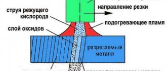
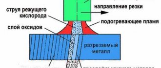
The separation cutting process begins with heating the part to be cut at the starting point of the cut with a heating flame 4 (Fig. 1) coming out of the heating nozzle 3, to the ignition temperature of the metal. Then cutting oxygen is launched through the channel of the cutting mouthpiece 2. The jet of cutting oxygen 5 comes into contact with the heated metal 1 and ignites it. During combustion, a significant amount of heat is released, which heats the underlying layers, and the combustion spreads throughout the entire thickness, burning a hole. If you move the cutter at the appropriate speed, the metal will be cut. The resulting slags 7 are blown out of the cutting cavity 6 by an oxygen stream.
Figure 1. Oxygen gas cutting: a - process diagram; b - universal cutter.
Manual oxy-fuel separation cutting is performed using a cutter. In Fig. 1, b shows a diagram of a universal injection cutter. This cutter is used for cutting steel with a thickness of 5 to 300 mm.
The cutter consists of a handle 7 with two nipples for hoses 5 and 6, a body 8, to which, using a union nut 11, a tip 13 is connected to a mixing chamber 12 and an injector 10. In the front part of the tip there is a cutter head 1, into which a tube is also soldered cutting oxygen 2. To supply gases to the cutter head there are valves 3, 4 and 9.
When cutting, you can use acetylene, coke oven gas, methane, hydrogen, lighting, petroleum, as well as liquid fuels - kerosene and gasoline.
The oxygen cutting mode is characterized by the power of the preheating flame, the pressure and consumption of cutting oxygen and the cutting speed, on which the quality and width of the cut depends. The duration of heating at the initial point of the cut with a preheating flame is determined by the thickness of the metal, its composition, flame power, type of fuel, etc.
The cutting speed is determined by the approximate formula
V = 40000/50 + δ ּ mm/min,
where δ is the thickness of the metal being cut in mm.
Cutting begins from the edge of the sheet. First, the heating flame is lit and then, when the metal is heated to white heat, cutting oxygen is released. If cutting begins in the middle of the sheet, then drill a hole in this place with a diameter equal to the width of the cut. The cutting speed is determined by the thickness of the sheet being cut, the flow rate and pressure of cutting oxygen. The distance from the cutter mouthpiece to the metal surface must always be maintained constant. When cutting steel 5–10 mm thick, the cutter is installed either vertically or at an angle of 5–10° to the metal surface in the direction opposite to the cutting direction. For thicknesses above 100 mm, the cutter is installed vertically in relation to the surface of the product.
When cutting metal with a thickness of more than 300 mm, the product should be heated in an oven to a temperature of 300 - 500 °. Cutting metal of large thicknesses is carried out with special cutters such as UBT-600 (thickness up to 600 mm) and R-100 (thickness up to 2000 mm). The latest cutter differs from the standard ones by the longer oxygen line and the presence of a so-called expanding nozzle. This nozzle promotes a higher gas flow rate than the nozzle of a conventional cutter. As a result, the oxides formed during cutting are blown out of the cut even at an oxygen pressure of 3-4 amu.
The main changes that occur in the metal in the cutting zone due to thermal and chemical influences include changes in structure and hardness. For medium-carbon steel (C content more than 0.3%, thickness 80 mm), the width of the heat-affected zone reaches 5 - 8 mm.
Batch cutting
Batch cutting is used for mass cutting of similar parts from sheets. The essence of the batch cutting process is that several sheets are folded together into a batch, tightly compressed with clamps and cut with an oxygen jet in one cutter pass. There are two methods of batch cutting: cutting with normal (high) pressure oxygen and cutting with low pressure oxygen.
With the first method, the thickness of individual sheets can be from 1.5-2 to 8-10 mm; the number of sheets in a package with a small steel thickness can reach 25-50. This requires that the sheets be well cleaned of scale and dirt and fit tightly together. A tight fit of the sheets is achieved by carefully straightening them and then compressing them with clamps.
The second method allows cutting even if there are gaps between the sheets of up to 3.5-4 mm or more; There is no need to compress the sheets.
. Cutting out parts according to the template.
When cutting with ordinary (high) pressure oxygen, the power of the preheating flame and the pressure of the cutting oxygen are set depending on the total thickness of the package. Due to the high power of the heating flame, severe overheating and warping of the top sheet are observed. It moves away from the underlying one and creates a gap, as a result of which cutting may stop. Therefore, pieces of waste sheets 6-8 mm thick are placed on top of the bag, which are clamped together with the bag. The cutting of the sheet package begins from the bottom edge. Then the cutter is gradually raised up the end of the bag to the top edge and then begins to be guided along the line of the intended cut. After cutting is completed, rapid cooling (for example, with water) is recommended to facilitate separation of the cut parts.
Mechanized cutting
For mechanized cutting, special machine cutters are produced. According to the principle of operation, they do not differ from manual ones. Their design allows for easy installation on gas cutting machines.
Mechanized oxy-fuel cutting of pipes.
The heating flame is controlled by an oxygen and gas valve. The metal is heated to a straw color, the cutting oxygen valve is opened and cutting is performed. If you need to extinguish the flame, first close the flammable gas valve, and then the oxygen valve. If the torch tip overheats, it is cooled with water, first closing the flammable gas valve, but leaving the oxygen valve open. If clogged, the mouthpiece is cleaned with a copper or aluminum needle.). Oxygen cutting machines are divided into stationary and portable. A portable machine is a self-propelled cart with electric, spring or pneumatic drive, on which an injection cutter and mechanisms for adjusting it to the cutting position are installed. The machine can be equipped with several cutters. It is installed on the workpiece to be cut (sheet, pipe, profile) and moves along it during the cutting process according to markings or a copier. Examples of portable machines: MPG-2 for cutting steel sheets 5...160 mm thick at a speed of 0.9...16 m/min, PGF-2-67 for cutting flanges and disks with a diameter of 50...450 mm from steel sheets 5...60 mm thick at a speed of 0.1...0.9 m/min. Stationary machines, depending on their design, are divided into portal (P), portal-cantilever (Pk) and hinged (W). Based on copying systems, there are machines with digital software (C), photocopying (F), magnetic (M) and linear (J1) - for straight cutting - control. According to the cutting method, the machines are designated: for oxygen (K), for plasma-arc (Pl) and gas-laser (GL) cutting. Oxygen cutting technology The parameters of the oxygen cutting mode include flame power, cutting oxygen pressure and cutting speed. The flame power is characterized by the consumption of combustible gas per unit time and depends on the thickness of the metal being cut. The power is chosen to ensure rapid heating of the metal at the beginning of cutting to the ignition temperature and the necessary heating during cutting. For manual cutting, the power required is 1.5…2 times more than for machine cutting. When cutting castings, it is increased by 3...4 times, since the surface of the castings is covered with sand and burnt marks. For cutting steel up to 300 mm thick, a normal flame is used, for larger thicknesses it is carburized with an excess of acetylene. The length of the torch of such a flame should be greater than the thickness of the metal being cut. The cutting oxygen pressure depends on the thickness of the metal, the shape of the cutting nozzle and the purity of the oxygen. With a thickness of 5...20 mm, the pressure can be 0.3...0.4 MPa, with 60...100 mm - 0.7...0.9 MPa. Excess pressure, as well as its lack, reduces cutting performance and deteriorates the quality of the cut surface. The cutting speed must correspond to the rate of metal oxidation along the thickness of the sheet being cut. At a slower speed, the upper edges of the sheet being cut will melt and a stream of sparks from the cut will flow out from the back side of the cut in the cutting direction. If the speed is too high, the spark beam will be weak and will deviate strongly in the direction opposite to the cutting direction. The cutting line will deviate from the vertical, lag behind, and the metal may not cut through. At normal speed, the flow of sparks should be calm and almost parallel to the stream of cutting oxygen, it only deviates slightly against the direction of cutting. Reducing oxygen purity by 1% reduces cutting speed by 20%. Therefore, it is necessary to use oxygen with a purity of at least 93.5% for cutting. When cutting, you need to maintain a constant distance between the mouthpiece and the surface of the metal being cut. It affects the quality of the cut and depends on the thickness of the metal: with a thickness of 3...10 mm, it is better to set this distance to 2...3 mm, with a thickness of 100...300 mm, 7...10 mm. Before cutting, you need to prepare the sheet to be cut. It must be laid on supports so that the gap between its bottom surface and the floor is at least 100 mm plus half the thickness of the metal being cut. Typically cutting is done in the down position. However, under installation conditions, the spatial position of the cut may be different; it has little effect on the quality of the cut. The surface of the sheet at the cut site must be cleaned. When cutting manually, a strip 30...50 mm wide is cleaned with a cutter flame. Before cutting on stationary machines, the sheets are first straightened on sheet-straightening rollers, and then the entire surface is cleaned chemically or mechanically (for example, shot blasted). The cutting process begins by heating the metal at the beginning of the cut to its ignition temperature in oxygen, then cutting oxygen is introduced and, making sure that oxidation of the metal has begun throughout its thickness, the cutter is moved along the cutting line.
21. Cutting thick metal is performed as follows. The cutter mouthpiece is first installed perpendicular to the surface of the metal being cut so that the jet of the heating flame, and then the cutting oxygen, is located along the vertical edge of the metal being cut. After heating the metal to the ignition temperature, a stream of cutting oxygen is released. The movement of the cutter along the cutting line begins after the metal is cut through its entire thickness at the beginning of this line. In order to prevent cutting lag in the lower layers of the metal, at the end of the process you should gradually slow down the speed of movement of the cutter and increase the tilt of the cutter mouthpiece to 10 ... 15° in the direction opposite to its movement. When cutting thick steel sheets, it is recommended to start process I from the bottom edge and apply preheating to 300 ... 400 ° C. In this case, cutting at an increased speed is possible. The speed of movement of the cutter must correspond to the speed of metal burning. If the speed of movement of the cutter is set correctly, then a stream of sparks and slag flies out of the cut straight down, and the edges are clean, without sagging or melting. At a high speed of movement of the cutter, the flow of sparks lags behind it, the metal at the lower edge does not have time to burn and the cutting process is disrupted. At a low speed, a sheaf of sparks is ahead of the cutter, the edges of the cut are melted and covered with smudges. The cutting oxygen pressure is set depending on the thickness of the metal being cut and the purity of the oxygen. The higher the purity of oxygen, the lower the pressure and oxygen consumption per 1 m of the section.
. The cutting process causes changes in the structure, chemical composition and mechanical properties of the metal. When cutting low-carbon steel, the thermal effect of the process on its structure is negligible. Along with areas of perlite, a nonequilibrium component of sorbitol appears, which even somewhat improves the mechanical properties of the metal. When cutting steel with a high carbon content, as well as alloying impurities, in addition to sorbitol, troostite and even martensite are formed. At the same time, the hardness and brittleness of the steel greatly increase and the machinability of cut edges deteriorates. Cold cracks may form. A change in the chemical composition of steel is manifested in the formation of a decarbonized layer of metal directly on the cutting surface, as a result of carbon burnout under the influence of a jet of cutting oxygen. Somewhat deeper than that of the parent metal, there is an area with a high carbon content. Then, as you move away from the section, the carbon content decreases to the initial value. Burnout of steel alloying elements also occurs. The mechanical properties of low-carbon steel remain almost unchanged during cutting. Steels with a high content of carbon, manganese, chromium and molybdenum are hardened, become harder and crack in the cutting zone. Stainless chromium and chromium-nickel steels, cast iron, non-ferrous metals and their alloys are not amenable to conventional oxy-fuel cutting, since they do not satisfy the above conditions.
Oxygen flux cutting
The essence of the oxygen-flux cutting process is that flux powder is introduced into the cutting zone, heated by a gas flame, along with a jet of cutting oxygen, which burns in oxygen, releasing heat that increases the temperature in the cutting zone - this is the thermal effect of the flux. The flux combustion products form liquid slags with the refractory oxides of the material being cut, which are removed from the cut by a stream of cutting oxygen - this is the chemical effect of the flux. And finally, the particles of flux powder do not burn immediately and, moving during the combustion process into the depth of the cut, by impact friction they erase refractory oxides from the surface of the edges, helping to remove them from the cut - this is the abrasive effect of the flux.
The increase in the amount of heat released during this process allows it to be used for cutting materials whose oxidation is associated with the formation of refractory and viscous compounds. The calculation of the flux composition for cutting specific metals is carried out using phase diagrams based on the conditions for obtaining a slag composition with a minimum melting point and viscosity.
Equipment for oxygen-flux cutting consists of a cutter, a flux feeder and a device for supplying flux to the cutter. Cutters for oxygen-flux cutting differ from cutters for oxygen cutting only in that the channels for supplying cutting oxygen are made with a larger diameter.
Three flux supply schemes are used: external, single-wire under high pressure and mechanical (Fig. 158). According to the first scheme, oxygen 2 is supplied to the upper and lower parts of the tank 1 with flux. In the upper part, pressure is created, and in the lower part, oxygen is blown into the hose 3, sucking (injecting) the flux. The gas-flux mixture is fed through a hose 3 into a head 5 placed on the cutter 4, coming out of the holes of which, it is sucked in by a stream of cutting oxygen and enters the cutting zone. With this scheme, any oxygen cutter can be used; you just need to put a head on it to supply flux. In a single-wire circuit, flux 3 is injected from the tank directly by a jet of cutting oxygen 6. The flux-oxygen mixture is supplied through a hose 3 through the central channel of the cutter 4. With mechanical supply, a screw 7 with an electromechanical drive 8 is installed in the lower part of the flux tank 1. When the screw 7 rotates, the flux is captured by it and is pushed through the hose 3 into the cutter head 4, where it is picked up by a stream of cutting oxygen 6.
Rice. 158. Flux supply schemes for oxygen-flux cutting:
a - external; b - single-wire under pressure; c - mechanical; 1 — tank with flux; 2 - oxygen; 3 - hose; 4 - cutter; 5 - head; 6 — jet of cutting oxygen; 7 - auger; 8 - electromechanical drive
The technique for oxy-flux cutting is basically the same as for oxy-fuel cutting. When using oxygen-flux cutting, the power of the preheating flame must be 15...20% greater so that the flux particles are evenly heated until ignited. The distance between the end of the mouthpiece and the surface of the sheet being cut is increased to 25 mm, and when cutting metal with a thickness of more than 100 mm - to 40...60 mm. This reduces the possibility of clogging the mouthpiece outlet channels. The cutting speed must be matched to the amount of flux supplied per unit time. The correct choice of flux consumption can be assessed by the presence of a small bead of molten iron on the upper edges of the cut. When the thickness of the metal being cut is 10...200 mm, the cutting speed is selected within the range of 0.76...0.23 m/min, and the flux consumption is 0.25...0.8 kg/h. The flux supply valve is opened after the heating flame is ignited. The duration of metal heating at the beginning of the process is much shorter than with oxygen cutting: for sheets with a thickness of 10...80 mm, heating requires from 15 to 120 s. The cutting oxygen pressure, for example, when cutting Kh18N10T steel with a thickness of 10...100 mm is 0.5...07 MPa.
Rice. 159. Scheme of cutting with an oxygen lance:
1 - steel pipe; 2 — handle; 3 - material to be cut; 4 - stand
Oxygen-flux cutting is used not only for metals, but also for cutting concrete and reinforced concrete. The difference is that since concrete does not burn in oxygen, when cutting, fluxes with greater thermal efficiency must be used than for metals. A good result is obtained by a flux consisting of 75...85% iron and 15...25% aluminum powders. Flux is supplied to the cutter via an external circuit using compressed air or nitrogen, blowing the gas-flux mixture into a stream of cutting oxygen. It is possible to cut concrete with a thickness of 90...300 mm at a speed of 0.15...0.04 m/min with a flux consumption of 20...42 kg/h. The process of cutting concrete with an oxygen lance is much more effective (Fig. 159). In this method, oxygen is blown through a steel pipe 1 (spear) with a diameter of 10...35 mm with a wall thickness of 5...7 mm and a length of 3...6 m. Steel rods are placed in large diameter pipes to increase their mass, small diameter pipes are wrapped with wire. The end of the pipe is heated by any heat source (for example, an electric arc or gas flame) to the ignition temperature in oxygen, then oxygen is supplied through handle 2 and the spear is pressed to the surface of the material being cut 3. As a result of the combustion of the end of the spear in oxygen, liquid iron oxides are formed, reacting with concrete and forming slags that are blown out of the cutting cavity. When cutting, the spear is periodically rotated and moved back and forth. The spear can be mounted on a rack 4, or in the hands of a worker. As the pipe burns, it is fed into the depth of the cut. In addition to oxygen, a gas-flux mixture can be supplied to pipe 1. This process is called powder lance cutting. Typically, a flux consisting of 85% iron and 15% aluminum powder is used. Spear cutting is used to remove profits from steel castings, to burn holes in thick metal before oxygen cutting, and to cut concrete and reinforced concrete up to 1200 mm thick.
When using oxygen-flux cutting, to prevent the flux from igniting in the cutter, hose or tank, you cannot use powders containing more than 96% pure iron or pure aluminum. When cutting copper, alloys with a high manganese content and when there is sand in the flux, you must use a respirator. When feeding flux through the cutting nozzle of the cutter, do not use fine, flammable iron powders. Regular checks of the cutter for proper operation are mandatory. When cutting with an oxygen or powder lance, the source of danger is an intense flow of hot slag particles scattered over a distance of several meters. This is a fire hazard and can cause burns to workers.
High-alloy steel, cast iron, copper and aluminum alloys, slagged metal, as well as non-metallic materials such as refractories and reinforced concrete are subjected to oxygen-flux cutting. The composition of fluxes for oxygen-flux cutting of materials is presented in Table 2.
Oxygen-flux cutting is widely used in heavy mechanical engineering and metallurgy for trimming casting profits, cutting blooms in a cold state, cutting pieces from hot ingots.
Table 2. Composition of fluxes for oxygen-flux cutting of materials
Spear cutting
The spear cutting method is used for cutting low-carbon and stainless steel and thick cast iron, as well as for cutting reinforced concrete.
The thickness of steel blanks cut with an oxygen lance can reach several meters.
There are two main methods of lance cutting: oxygen and oxygen-powder lance (oxygen-flux cutting).
Burning holes in a cut blank of steel or cast iron or in reinforced concrete is done with the end of a steel tube (spear), into which oxygen is continuously supplied under pressure. The heat necessary for the process is created by combustion of the end of the tube and the iron of the processed blank.
At the beginning of the process, the end of the tube is heated to ignition temperature by a torch or electric carbon arc. The oxygen pressure at the beginning of the process is 2-3 kgf/cm2, and when the working end of the spear goes deep into the metal to 30-50 mm, the oxygen pressure is increased to 8-15 kgf/cm2, depending on the thickness of the metal being burned.
To avoid welding the heated end of the spear to the wall of the hole, the spear periodically performs reciprocating movements within 100-150 mm, turning one turn in both directions. When burning holes in reinforced concrete, welding of the spear is excluded, so only rotational movements are made with it.
As a spear, a steel gas tube with a diameter of , with 3-4 pcs. low carbon wire with a diameter of 5 mm. These wires, when the end of the spear burns, increase the amount of heat generated at the cutting site. Oxygen is supplied to the lance tube from the cylinder ramp through a hose with an internal diameter of 13 mm, connected to the tube through a lance holder with a collet or bolt clamp.
When using powder-oxygen lance cutting, after heating its end and supplying oxygen, powdered flux begins to be fed into the lance tube, which burns upon exiting the tube, forming a flame 100-150 mm long with a temperature of about 3500-4000 ° C. When cutting and burning holes In this case, the end of the spear is kept at a distance of 30-100 mm from the wall (bottom) of the hole being burned. A mixture of 80% iron and 20% aluminum powder is used as a flux.
By moving the spear in a horizontal or vertical direction, using these methods you can not only burn holes, but also cut blanks, cut off castings, and cut holes in reinforced concrete, brick and stone building structures.
Oxygen spear cutting.
Oxygen lance cutting is effective for burning holes in concrete. With this method, oxygen is supplied through a steel pipe (lance), one end of which is heated to the melting temperature and pressed against the surface of the concrete. Oxygen, interacting with the hot end of the pipe (spear), is oxidized, forming liquid iron oxides. These oxides react with concrete and turn into slag, which is easily blown away. By pushing the spear forward, we achieve penetration deep into the concrete mass and, ultimately, burn a hole. It is good for these purposes to use a thick-walled seamless pipe with a diameter of 20-35 mm; a thin-walled gas pipe with a diameter of 10.2-21.3 mm, filled 60-65% with steel rods, or a thin-walled gas pipe of the same diameter, wrapped on the outside with steel wire with a diameter of 3-4 mm. Rods and wires play the same role in the cutting process as iron powder does in oxy-flux cutting. Heating of the pipe (spear) before cutting is usually done with a gas burner or carbon electrode.
In Fig. The simplest diagram of burning a hole with a spear is shown. This technology makes it possible to obtain holes with a depth of up to 4000 mm and diameters of up to 1200 mm. The same method can be successfully used when burning holes in a steel workpiece.
Rice. Burning concrete with an oxygen lance. 1 - concrete; 2 - spear; 3 — protective screen; 4 — handle for feeding and rotating the spear during operation; 5—oxygen supply; 6—air supply with flux
Powder-spear cutting.
Powder-spear cutting differs in that instead of wire (rods) iron powder is used, which contains 85% iron and 15% aluminum powders. This powder (like flux) is fed into the cutting area along with a stream of oxygen.
The recommended operating modes are as follows:
1. If you need to burn a hole with a diameter of 55 mm and a depth of 500 mm, you must provide an oxygen pressure of 0.7 MPa and have a supply of powder at a consumption rate of 30 kg per hour. In this case, the cutting speed can be in the range of 120-160 mm per minute, and the estimated consumption of the spear (pipe) will be 4 mm per 1 meter of hole length.
If the hole depth is greater (within 1500 mm), then the oxygen pressure should be 1.0-1.2 MPa, the flux consumption will not increase (30 kg per hour), the cutting speed will drop to 40-70 mm per minute, and the spear consumption will increase to 6 mm per 1 meter of hole length.
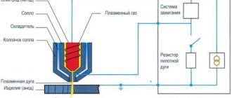
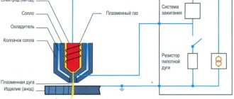
Plasma arc cutting
Plasma arc cutting is based on the ability of a compressed arc to penetrate deeply into the metal, melting it along the cut line with an arc discharge. Under the influence of the high temperature of the compressed arc, gas 2, passing through the arc discharge, strongly ionizes, a plasma jet is formed, which removes the molten metal from the cut site. Arc 1 is excited between the metal being cut 4 and a non-consumable tungsten electrode 5 located inside the cutter head 6. Arc gas-discharge plasma 3 is called low-temperature (its temperature is 5000–20,000°C).
The plasma-forming gases used in plasma-arc cutting must ensure the production of plasma and the necessary protection of the tungsten electrode from oxidation. Argon, nitrogen and mixtures of argon with nitrogen, hydrogen and air are used as such gases. Lanthanated tungsten VL-15 is used as electrodes. The tungsten electrode is placed with the plasmatron nozzle. The plasma jet has a high outflow velocity and the shape of an elongated cone, the cross-section of which at the exit corresponds to the cross-section of the nozzle. Plasma arc cutting is used to cut metals that are impossible or difficult to cut by other methods, for example, when cutting corrosion-resistant alloy steels, aluminum, magnesium, titanium, cast iron and copper. When cutting with a plasma jet, the metal being cut is not included in the electrical circuit of the arc. The arc burns between the end of the tungsten electrode and the inner wall of the water-cooled tip of the plasma torch. The essence of plasma arc cutting is to melt the metal with a plasma jet and blow out the molten metal from the cutting zone.
Scheme of the plasma cutting process: a - plasma arc, b - plasma jet
The figure schematically shows the plasma jet cutting process. Power is supplied from a direct current source 3. The minus is supplied to the tungsten electrode 4, and the plus is supplied to the copper nozzle 2, which is cooled by water. The arc 6 burns between the electrode and the nozzle and is blown out by a gas mixture from the internal cavity of the mouthpiece 5 to form a plasma jet that melts the metal 7 being cut. Argon and a mixture of argon and nitrogen are mainly used as plasma-forming gas. A plasma jet is used when cutting thin metal. The cutting speed of a plasma jet depends on the properties of the metal being cut and on the parameters of the cutting mode (current strength, voltage, gas flow). A plasma jet can be used to cut both manually and mechanizedly. For plasma arc cutting, special equipment is used that is powered by electrical energy. The main element in plasma cutting is a device for controlling the cutting operating cycle - supply and shut-off of gases, ignition of the pilot arc.
For manual plasma cutting, a RDM-2-66 plasma torch is used. The plasma torch consists of a head 4, a mouthpiece with a forming nozzle 3 and a handle 5. The cutter head has a water-cooled body, to which water is supplied and discharged through sleeves 8. The mouthpiece is isolated from the current-carrying body with a rubber gasket. The valve block, mounted on the handle, consists of a valve for supplying argon 10 with fitting 9, a lever valve 6, which allows cutting in a mixture of argon with hydrogen or nitrogen, and fitting 7. The cutter has a support roller 2 and a shield 1. In the cable The hose package includes two gas hoses - for argon and hydrogen or nitrogen and two water cooling hoses. In one of the cooling sleeves there is an operating current cable with a cross-section of 10 mm2, which is connected to the minus of the power source.
The RDM-2-66 plasma torch is designed for manual separation cutting of aluminum and its alloys up to 25 mm thick and stainless steels up to 20 mm thick.
Plasmatron RDM-2-66
The VNIIavtogenmash Institute, based on the RDM-2-66 hand-held plasma torch, created the water-cooled RDP-1 hand-held plasma torch and the air-cooled RDP-2 plasma torch.
The RDP plasma torch is shown in the figure. It consists of a head with a forming nozzle, a handle with a support roller and a shield, and a control unit, which is mounted on the inlet gas communication. Along the axis of the head there is a collet clamping device in which a tungsten electrode is secured. At the rear of the handle there is a button for remotely turning on and off the power source and a valve for supplying working gas is located.
RDP cutter from the set of universal KDP equipment
The power source is welding rectifiers of the VKS-500 type. The universal set of equipment KDP-1 with plasma torch RDP-1 is designed for the highest operating current of 400 A and is intended for cutting aluminum and its alloys up to 80 mm thick, stainless steel up to 60 mm thick and copper up to 40 mm thick. Argon and mixtures of argon with nitrogen or hydrogen are used as gases.
The set of universal equipment KPD-2 with plasma torch RDP-2 is designed for a maximum operating current of 200 A and is intended for cutting aluminum and its alloys up to 50 mm thick, stainless steel up to 40 mm thick and copper up to 25 mm thick. The RDP-2 cutter can be used at assembly and construction sites outdoors at any temperature.
Diagram of external connections of the KDP-1 kit
The installation diagram of KDP-1 for plasma-arc cutting is shown in the figure. It consists of cylinders), a current source 2, cooling water 3, a collector 4, a cable package 5 and a cutter 6. The efficiency installation works according to the following principle: set the operating pressure on the gas cylinders, open the water supply valve to cool the cutter and turn on the source switch nutrition. Open the gas valves on the plasmatron and by pressing the button on the handle close the electrical circuit with the electrode. Then, a lighter rod is inserted into the cutter nozzle, from which a stream of argon flows, and the gap between the electrode and the tip is closed. At the moment the rod is removed, an auxiliary arc occurs between the electrode and the nozzle tip, and a jet of arc plasma is blown out of the nozzle. The tip of the plasma torch is brought to the beginning of the cut, and at the moment of contact with metal 7 the cutting arc is excited. At the same time, by pressing the valve lever on the plasmatron, the supply of working gas is opened and the auxiliary gas channel is closed. To stop cutting, it is necessary to move the plasma torch head away from the surface of the metal being cut. The power source in all KDP installations is two VDG-501 rectifiers, which are connected in series, which provides an open circuit voltage of 180 V.
For semi-automatic plasma-arc cutting, semi-automatic machines of the PRP type are used. The installation consists of a PRP-1 plasma torch, a VDG-500 rectifier and a trolley. The semi-automatic plasma torch consists of a cylindrical body with a collet-mounted tungsten electrode. The internal nozzle is isolated from the cathode system and included in the pilot arc circuit. In parallel with this circuit, the discharge circuit of the high-frequency oscillator is connected. This allows you to press the start button not only to apply voltage, but also to initiate an arc between the cathode and the internal nozzle. Simultaneously with the initiation of the auxiliary arc, the engine of the mobile cart is turned on and the auxiliary arc is brought to the edge of the metal being cut; at the moment of contact with the metal, the main arc appears. Cutting is stopped by pressing the button.
For plasma-arc cutting of non-ferrous metals and alloys, as well as stainless steels, the URPD-67 installation is used. The installation operates on argon-hydrogen or nitrogen-hydrogen mixtures. Two PSO-500 welding converters are used as power sources, which are connected in series. The plasma torch for manual cutting is equipped with a trolley.
GOST 12221-79 establishes four types of equipment for plasma-arc cutting: Plr - for manual cutting, Plrm - for manual or machine cutting, Plm - for machine cutting, Plmt - for precision machine cutting. For machine cutting, devices of the types Plm-10/100, Plm-60/300, Plm-160/630, Plmt-50/300 are used.
Devices of the PLM-10/100 type are called devices for microplasma cutting. For this type of cutting, the AVPR-3 device, developed by the Institute of Electric Welding named after. E. O. Paton. The AVPR-3 device consists of a power supply and a microplasma torch VPRM-1. The torch can be installed on ASH, SGU machines, a welding tractor or a portable cart.
Devices of the PLM-60/300 type include the air plasma cutting installation UVPR "Kyiv". It consists of a power supply, a control cabinet and a VPR-9 cutting plasma torch with a bushed zirconium cathode. The plasma torch has a vortex arc stabilization system. Compressed air is used as a plasma-forming gas. The VPR-9 plasma torch can be installed on portal-console and portal cutting machines.
The power of the cutting arc in devices of the PLM-160/630 type reaches 180 kW. They consist of a power source, a control cabinet and a cutting plasma torch. Devices of this type include EDR-2, UPR-601 and OPR-6-2M units. Argon and a nitrogen-hydrogen mixture are used as plasma-forming gases. Cutting plasma torches are installed on large cutting machines or on heavy self-propelled trolleys of the PPL-1 type, the movement speed of which can be adjusted within the range of 50-10,000 mm/min.
Devices of the Plmt-50/300 type provide cutting of parts according to the first accuracy class. They are designed for work with a rigidly stabilized arc at high voltages. The cutting plasma torch CA-142 operates on a mixture of argon, hydrogen and nitrogen.
Of the foreign devices of this type, the RA-20-2 (GDR) device is widely used. It consists of a power source, an automation and control unit mounted in one housing, a circulation pump and cutting plasma torches. The device is equipped with a machine plasma torch RV-20-3 and a manual plasma torch RV-20-N. Argon-hydrogen and nitrogen-hydrogen mixtures and compressed air are used as plasma-forming gases. When switching the operation of the plasma torch from gases to compressed air, the sleeve cathode with a tungsten insert is replaced in the plasma torch with a cathode with a zirconium insert. The type and brand of plasma arc cutting machine must be selected based on their purpose and requirements for cut quality.
Flame cutting sequence
An important feature of flame cutting is the need for two gases, one of which – oxygen – performs the actual separation of the metal, and the second – propane or acetylene – heats the cutting area. Such heating is required in order to gradually increase the temperature of the metal in the separation zone, and thus avoid undesirable changes in the surface structure of the workpiece as a result of rapid heating.
Gas plasma cutting equipment
However, this cannot be avoided
Therefore, one of the important indicators of the oxy-fuel cutting process is the depth of the heat-affected zone - the part of the workpiece thickness in which changes in its macro- and microstructure occur. Such changes often strengthen the workpiece, and this negatively affects its subsequent processing (no matter mechanical or deformation)
After cleaning the workpiece, its surface is heated to a temperature of 1000...1200C, after which the oxygen supply is turned on. At such temperatures in the cutting zone, oxygen quickly ignites, forming a narrowly directed flame jet, which cuts the metal.
Gas plasma cutting process diagram
An indispensable condition for the quality of the cutting process with a flame torch is the continuity of oxygen supply. Otherwise, the surface quickly cools, and smudges of frozen metal form at the point where the jet breaks. The fact is that the surrounding surface has a significantly lower temperature, and turning on the propane supply and heating occurs more slowly than the cooling of the metal. That is why, in especially critical cases, this cutting method is implemented on specialized equipment equipped with automatic process control.
The preheating process time depends on:
- Metal thickness;
- Brands of the material being separated (for example, stainless steel has low thermal conductivity and therefore heats up more slowly);
- Surface quality (degreased workpiece warms up faster).
The permissible warm-up time should not exceed 30...40 seconds.
Plasma cutting modes
The process itself begins from the edge of the sheet, where the conditions for the exit of the jet are best
This is especially important when cutting thick sheet metal (more than 50...60 mm) with a hand cutter. Next, move the mouthpiece evenly along the separation surface, maintaining a constant distance between the head and the surface of the workpiece.
Cutting quality
The cutting quality is affected by:
- oxygen consumption
. Lack of oxygen leads to incomplete oxidation of the metal and insufficient removal of oxides; and excess leads to cooling and removal of heat from the cutting zone. - purity of oxygen
. Reduced cleanliness affects the quality of cut edges; The lower the cleanliness, the more difficult-to-remove slag adheres to the lower edge of the cut. - heating flame power
; Depending on the composition of the mixture, the flame can be oxidizing, normal, or carburizing. Oxidizing – for cutting steel 3–8 mm thick. Normal - for thicknesses of 10–100 mm. Carburizing - for large thicknesses. - the total length of the flame
must be greater than the thickness of the metal being cut.
Preparing cutting equipment
Place the metal to be processed in a comfortable position, preference is always given to the lower one.
| If necessary, cutting can be carried out in all positions. In order for the molten slag to flow freely from the cutting zone, there must be free space under the heated sheet L (mm), L = S/2 + 100, de S—thickness of the metal being cut, mm; Depending on the thickness of the metal being cut, install the required inner and outer mouthpieces. |
Basic design of a cutting torch
Design features of the cutter.
Injection or two-pipe cutter
This is the most popular model due to its design. The name “two-pipe” comes from the division of technical oxygen into two streams. This is done to functionally separate the work of oxygen.
The second flow of oxygen goes straight to the injector. The operating procedure in the injector chamber is as follows: oxygen enters the chamber under high pressure and at high speed, as a result of which a rarefied pressure zone is formed in this space. Oxygen is injected in this case.
Nominal gas flow.
Through special side holes in the walls of the chamber, flammable gas is drawn into it - in this case it is ejected. The gases are mixed, the velocities are equalized, and as a result, a flow of a mixture of gases is formed at the exit from the chamber, the velocity of which is lower than that of the injected oxygen, but higher than that of the ejected combustible gas.
At the next stage, the formed mixture of gases enters the tip - first into its head, and then exits through the nozzle between the mouthpieces and forms the same flame in the form of a torch, which heats the metal to its combustion temperature. All gas flows are regulated by their own valves on the outside of the housing - for supplying oxygen and separately for supplying flammable gas to the injector.
Injectorless or three-pipe gas cutter
In this case, the device of the gas cutter is more complicated. Oxygen enters it through two tubes, and the third tube is rightfully occupied by flammable gas. In this welding torch, gases are mixed inside the head; there is no chamber here. This system is safer than the two-chamber model.
This model has a significantly higher cost. In addition to this drawback, the three-pipe cutter has one more nuance: when working with it, a very high pressure of flammable gas is required - higher than with an injection apparatus.
Metal cutting instructions
It is important to connect and prepare the torch correctly. Tubes with valves at the ends are connected to the cylinders
Next, the gas supply is checked (if it is oxygen-propane metal cutting) - the valve closes, the valve on the cylinder opens. Then, watching the pressure gauge, the valve is slowly opened. The pressure should be 0.35–0.55 atmospheres. Then you need to blow out the hose - open the valve. Gas begins to escape with a characteristic sound. If the pressure gauge shows stable pressure, the valve closes.
The next step is to check the oxygen supply and adjust the pressure. First, the valve on the cylinder opens, then the regulator (flow pressure 1.7-2.7 atmospheres). To purge the hose, open the oxygen valves on the cutter. There are two of them: for feeding into the nozzle and forming a mixture. First you need to open the first one, then the second one (for 3-5 seconds).
The gas supply valve is opened first to allow oxygen to escape, which remains in the mixer after checking. The valve must be turned until gas can be heard escaping. The lighter placed in front of the cutter should touch the mouthpiece. After pressing the lever, sparks ignite the gas.
You need to open the oxygen valve immediately. Its sufficient volume is indicated by a change in the color of the flame to blue. In order for the torch to increase in size, more oxygen must be supplied. The pressure of gas and oxygen when cutting metal depends entirely on the thickness of the workpiece.
According to the technology of gas cutting of metal, the flame was brought to the material with the tip, heating the surface. After the molten metal appears, the supply of oxygen begins, igniting it. The jet increases until the material is completely cut through. At the same time, the mouthpiece moves along the cutting line. Sparks and slag are removed with a jet.
The optimal cutting speed is determined by the sparks - they should fly away at an angle of 85-90 o. If the angle is smaller, the speed must be reduced. If the workpiece is thick, it must be placed at an angle to allow the slag to drain. It is not recommended to stop without finishing the process. At the end of the work, first the oxygen is shut off, then the gas.
Oxygen cutting process
The oxygen cutting process is based on the property of metal combustion in a stream of oxygen and the removal of the resulting oxides by this stream.
Before starting this process, you should familiarize yourself with the technique of oxygen cutting.
The cutting process begins with heating the metal to the ignition temperature, the heat of the metal combustion reaction that develops in this case contributes to the further heating of neighboring particles to the ignition temperature, due to which the cutting stream of oxygen continuously penetrates to the entire depth and cuts through it, while part of the metal along the cutting plane turns into metal oxides and blown out with a stream of oxygen.
For a stable cutting process, the following conditions must be met:
1.The combustion temperature of the metal must be lower than the melting temperature of the metal; otherwise, the metal will melt and drain before it has time to burn.
2. The slag formed during cutting, consisting mainly of metal oxides, must be fusible and fluid, and drain under the influence of a stream of cutting oxygen.
3. The heat released by the combustion reaction of the metal must be sufficient to ensure the continuous continuation of the cutting process that has begun.
4. The thermal conductivity of the metal must be low enough to prevent large heat losses from the cutting site for useless heating of the entire mass of metal.
5. The melting point of the metal must be higher than the melting point of the oxides; otherwise, the oxides formed during the cutting process will not be able to separate from the base metal and will not be continuous. These conditions are met by iron (steel), titanium (and its alloys), and manganese.
Cutability of steel and the influence of carbon and alloying elements on oxygen cutting of steels
The ability of metals to undergo oxyfuel cutting depends on how fully the above conditions are satisfied.
Effect of carbon on cutability
| Metal | Cutability characteristics |
| Low carbon steel | Cutability is good at carbon contents up to 0.3% |
| Medium carbon steel | As the carbon content increases from 0.3% to 0.7%, cutting becomes more difficult |
| High carbon steel | When the carbon content is above 0.7% to 1%, cutting is difficult and preheating of the steel to a temperature of 300-700°C is required. If the carbon content is more than 1-1.2%, cutting is impossible (without using flux) |
Manganese (Mn) - makes cutting easier. Impairs cutting when the content is more than 4%.
Silicon (Si) - steels with a carbon content of up to 0.2% and Si up to 4% are cut well.
Chromium (Cr) - steels with a Cr content of up to 1.5% are cut well, with an increase in the content, cutting becomes difficult, and with a content above 8-10% - oxygen cutting is impossible (oxygen-flux or air-plasma cutting is used here).
Nickel (Ni) - steels with a Ni content of up to 0.7% are cut well, if the carbon content in the steel is no more than 0.5%, then it is cut well with a Ni content of up to 4-7%, with a content of more than 34% - cutting deteriorates .
Copper (Cu) - steels with a Cu content of up to 0.7% cut well.
Molybdenum (Mo) - ordinary molybdenum steels are cut satisfactorily at a content of up to 0.25-0.3%, cutting is not difficult, but the cutting edge is hardened.
Tungsten (W) - steels with a W content of up to 10% are cut well and satisfactorily; with a content above 10%, cutting is very difficult.
Sulfur and Phosphorus (S and P) - when the content of these elements is within the limits specified by the standards - does not affect cutting.
Main indicators of oxygen cutting mode:
- flame power
- cutting oxygen pressure
- cutting speed
The power of the flame depends on the metal being cut, the composition and condition of the steel (rolled, forged, casting). When cutting manually, due to the uneven movement of the cutter, the flame power is usually increased by 1.5-2 times compared to machine cutting. When cutting castings, because The surface of the casting is usually covered with molding earth and burnt marks, the flame power increases by 3-4 times.
For cutting steels up to 300 mm thick, a normal flame is used, and for metal thicknesses over 400 mm, it is advisable to use a preheating flame with excess acetylene (carburizing) to increase the length of the torch (in addition to using a higher oxygen pressure) and warming up the lower part of the cut.
The choice of cutting oxygen pressure depends primarily on the thickness of the metal being cut and the purity of the oxygen. At higher pressures, mouthpieces with a larger diameter cutting oxygen channel are used. For each mouthpiece (external and internal) there is an optimal pressure value, when changing in one direction or another, the quality of the cut deteriorates and the cutting speed changes. Accordingly, oxygen consumption may increase by 1 lin. m. For these reasons, you should strictly follow the operating documentation for hand and machine cutters.
The cutting speed must correspond to the rate of oxidation (burning) of the metal across the thickness of the sheet being cut.
At a slower speed, the upper edges of the cut sheet melt and molten oxides (slag, flash) fly out of the cut in the form of a beam of sparks in the direction of the cut.
If the speed is too high, the emission of sparks from the cut is weak and directed in the opposite direction of the cutter's movement. The cut mark on a vertical surface lags significantly behind the vertical. Possible failure to cut through metal.
At optimal cutting speed, the flow of sparks from the back side of the sheet being cut is relatively calm and directed almost parallel to the oxygen stream. The cut mark is only slightly behind the vertical, the roughness of the cut is insignificant and the burr is easily separated from the lower edge of the cut. The cut is smooth.
The article was developed with the support of the site www.pgn.su. This is the official website of NPP PromGrafit, which offers modern sealing materials and thermal insulation of its own domestic production.