Introduction
Currently, one of the pressing problems of mechanical engineering is improving the quality and reliability of structures while simultaneously increasing labor productivity and production automation.
Requirements for improving the quality and reliability of welded structures are met by correctly selecting the type of welding, welding materials, and calculating the most rational welding mode.
Welding is one of the leading technological processes of modern industry, the degree of development and improvement of which largely determines the level of technology in mechanical engineering, construction and a number of other sectors of the economy. A properly developed welding process ensures the production of not only reliable connections and structures that meet all operational requirements, but also allows for the maximum degree of comprehensive mechanization and automation of the entire production process for manufacturing parts, and is cost-effective in terms of energy costs, welding materials and human labor costs. The advantages of welded structures are now generally recognized; such structures are widely used instead of cast and riveted joints. These advantages boil down to reducing metal consumption, reducing labor costs, simplifying equipment, and increasing productivity.
In the designed technological process for the manufacture of box profile beams, special attention is paid to increasing labor productivity, mechanization and automation of welding work through the introduction of new high-performance equipment and the use of new welding materials.
I-beams, box beams and crane beams
Welding is the most popular and effective process for manufacturing beams, I-beams, crane beams, box beams, etc. Welded beams are used in various fields - both in the manufacture of bridges and crane structures, and in the construction of any public buildings.
Welded beams are also used in the manufacture of simple metal structures, which is explained by their reliability in operation and fairly simple manufacturing technology.
Beam welding technology is a process of welding long longitudinal seams. These are usually T-welds or butt welds. To automate the welding of such seams in the manufacture of T-beams, box-shaped and other beams, welding carts and tractors are usually used.
Welding carts and tractors
Welding tractors perform straight longitudinal seams. The welding head is mounted on a welding tractor, which moves along the seam either along the beam belt, or along a separate guide located directly along the beam welding area. The welding tractor may have a welding torch oscillation unit, which allows the production of filling welds. The tractor's moving speed is adjustable and allows the use of highly productive processes.
Welding columns
The welding column is a vertical mast with a horizontal boom, at the end of which a welding head is attached. A boom column has two main dimensions: mast height and boom length. Quite often, the column is installed on a trolley podium, which can move along a rail track at welding speed. Thanks to this, columns are used for automatic welding of beams.
High-performance welding processes for automatic beam welding
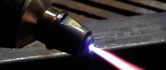
The most commonly used welding processes in the manufacture of welded beams are submerged arc welding (SAW - Submerge Arc Welding) and arc welding (MIG/MAG, TANDEM). Recently, the relatively new innovative hybrid laser-arc welding process Laser Hybrid has become interesting for welding beams.
Submerged arc welding has its advantages compared to other processes, but among the main disadvantages is that it cannot be performed in all spatial positions. The large dimensions and weight of the welding head reduce accessibility to the welding seams of the beams.
The advantages of arc processes are welding in all positions, in particular vertical seams, and the fact that there is no need to use welding flux. Thanks to this, it is possible to reduce or completely eliminate the number of edgings of a welded beam during its manufacture. When using the TANDEM welding process and the Laser Hybrid process in combination with welding robots, the same productivity as submerged arc welding is achieved.
Special process for welding beams
The high productivity of the TANDEM welding process is ensured by the simultaneous supply of 2 welding wires with separate electrical potentials into one weld pool. Thanks to this, it becomes possible to control arc combustion and seam formation at high welding speeds (up to 5 m/min) and low heat input. This is very important for welding beams, as it affects its warping.
The advantage of the Laser Hybrid welding process is that it saves materials and in some cases eliminates the need for edge preparation for welding, such as butt joints.
© Smart Technics This article is a copyrighted product, any use and copying on the Internet is permitted with the obligatory indication of a hyperlink to the website www.smart2tech.ru
Welding process for welding beams:
Welding process TANDEM welding
Laser Hybrid welding process
Design purpose and requirements for welded joints
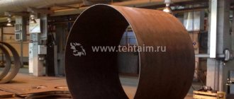
A box-section beam is a welded structure of four metal plates welded together to form a closed loop. Such structures are widely used in the construction industry as various types of supports and load-bearing structures. The advantage of using box-shaped beams is that the metal beam works more fully under various kinds of bends (compared to an all-metal beam), while having a relatively small mass.
The beam is made of structural low-alloy steel grade 09G2. The operating conditions of the structure are normal, the operating temperature range is from -30 to +50 degrees.
The design must withstand maximum permissible loads during the design service life, ensure durability and reliability, and provide for the possibility of technical inspection, repair and inspection of the metal in the connection.
The main types, structural elements and dimensions of welded joints performed by submerged arc welding must comply with GOST 8713-79, GOST 11533-75.
The quality of welded structures is determined by:
- rational design;
- quality of the base material; quality of welding materials, flux (compliance with certificate, state standard or technical specifications);
- quality of part assembly;
- quality of surface preparation of parts for welding;
- the level of the developed technological process, the degree of automation of assembly and welding operations;
- qualifications of welders, operators and adjusters, general production culture;
- weld quality: i.e. made without defects, in accordance with the requirement of strength, smooth transitions to the base material.
Incoming parts for welding must meet the requirements of the drawing. The welded edges of the parts in the places where the seams are applied and the adjacent edges with a width of at least 20 mm in each direction must be cleaned of scale, rust, paint, lubricant oil and other contaminants to a metallic shine. Control of stripping dimensions is carried out using a metal measuring ruler or a caliper.
Parts prepared for welding should not have sharp edges. After stamping, parts intended for welding must be cleaned of oil, grease, and dirt using washing solutions.
Manufacturability is understood as design optimal forms that meet the service purpose of the product, ensure operation within a given resource, and allow the product to be manufactured with minimal costs of material, labor, and time.
A design can be considered technologically advanced when:
- The material has good weldability, is not prone to the formation of cold and hot cracks, embrittlement, is not sensitive to the formation of hardened structures, has a low tendency to red brittleness, cold brittleness, is heat-resistant, and corrosion-resistant.
- The design of the product allows the use of mechanization and automation of assembly, welding and transport operations.
- The design can provide free access of electrodes to the welding site. those. connection type - open.
Based on the above, we conclude that the design is technologically advanced.
Features of the manufacturing technology of welded box-section beams
Box-section beams (Fig. 36, a) are more difficult to manufacture than I-beams, but they have greater torsional rigidity and therefore are widely used in crane bridge structures. If such beams are long, the shelves and walls are welded with butt joints from several sheet elements.
Rice. 36. Manufacturing of box-section beams: a - section of beams; b - installation of side walls; c - welding of internal seams |
First, the top chord (shelf) is placed on the rack, the diaphragms are placed and welded to it. This sequence is determined by the need to create a rigid foundation for further installation and ensure the straightness of the side walls, as well as their symmetry relative to the upper chord. After welding, the diaphragms are installed, pressed (Fig. 36, b) and the side walls are grabbed. Then the assembled U-shaped profile is turned over and the walls are welded to the diaphragms using internal fillet welds (Fig. 36, c). The assembly is completed by installing the lower belt. Welding of waist seams is carried out after completion of assembly and is carried out
with an inclined electrode without turning to the “boat” position. This is explained by the fact that for a box-section beam, the undercut at the waist seam is less dangerous than for an I-beam, since in box-section beams concentrated forces are transmitted from the waist to the wall not directly, but mainly through transverse diaphragms.
In the manufacture of full-size crane bridge beams, all main operations for the preparation of sheet elements and subsequent general assembly and welding are performed in mechanized production lines using automatic submerged arc welding. The bottleneck in the production of such box-section beams is the T-joint of the diaphragms and walls using fillet welds. The small distance between the walls makes automatic welding in a horizontal position difficult (Fig. 36, c), and manually the welder has to make these seams in an extremely uncomfortable position.
We will consider the features of the production of box-section beams using the example of a production line (Fig. 37). All procurement operations are performed off-line, and warehouse 11 receives fully processed workpieces. Portal crane 10 with electromagnetic grippers alternately supplies shelf and wall blanks to roller conveyor 9. In the welding stand 8, the transverse joints of the beam elements are assembled and submerged arc welded in one pass with the reverse formation of a seam on a cooled copper pad. As the transverse joints are welded, the beam element moves along the roller conveyor to X-ray inspection area 7. Typically, all transverse seams of the lower chord experiencing tensile stresses are subjected to X-ray inspection, and the seams of the remaining elements are controlled selectively. The finished elements are removed from the stand by an overhead crane using a rigid cross-beam and installed in a vertical position into storage tanks 6. In the same way, these elements are fed from the storage tanks to the assembly stands. Stands 1, 2, 3 and 5 represent
a system of tragus placed parallel to each other at a distance of 1.5…2
72
| sections |
m. At stand 5, the upper belt with diaphragms - the “comb” - is assembled and welded. It is carried by an overhead crane to stand 3, moored with eccentric grips by the diaphragms in several places using a rigid crossbeam. The central trestles of stand 3 are height adjustable. This allows you to set a deflection to the upper chord equal to the construction rise, if it is necessary to compensate for the deflection of the beam when the structure operates under load. During assembly, this preliminary deflection of the belt is secured by placing the side walls, which must be kept in mind when designing their cutting. The assembly of the side walls with the “comb” is carried out using a self-propelled portal installation 4. To weld the diaphragms with the walls, a portal installation 12 is used, which carries four heads for simultaneous execution of four vertical fillet welds in a CO 2 environment.
The assembly of the beam is completed at stand 2, where the open-section beam assembled at stand 3 is transferred without tilting by an overhead crane. Before installing the lower chord, the curvatures of the upper edges of the side walls resulting from welding the diaphragms are straightened. To do this, hydraulic jacks located on trolleys 14 are brought to the ends of the beam and, pressing on the upper chord, bend the beam until its construction lift is completely removed. The edges of the vertical walls are stretched in the elastic region, and the curvatures are eliminated. Then the lower chord is laid using an overhead crane. Using a self-propelled portal 13, which has vertical pneumatic cylinders, the belt is pressed against the beam and secured with tacks. After the beam is released from its fastening, the construction rise is restored. Next, the beam is transferred to a stand / for welding the waist seams with an inclined electrode. Along the stand 1, two automatic welding machines 15 move along rail guides, performing; two waist seams are submerged at the same time. The machines are equipped with remote welding heads, hinged. During the welding process, springs constantly press the head against the beam, and a follower roller guides the electrode to lay the waist seam. After edging the beam, the second pair of seams is performed in the same way.
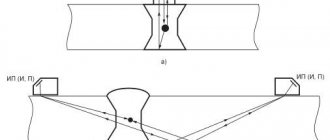
Welded box-section elements have found application as truss rods for railway bridges (Fig. 38, a). Unlike beams, they do not have diaphragms, which makes them difficult to assemble. Therefore, in mass production, special jigs are used to assemble them, fixing the parts along the outer contour (Fig. 38, b). In addition, to prevent helical curvature of these elements, welding is carried out by simultaneously applying two fillet welds symmetrically located in the same plane with inclined electrodes. For this purpose, double-arc tractors of the TS-2DU type are used.
Rice. 38. Conductor for assembling box-section rods: a - cross-section of the rod; b - conductor diagram |
Base metal weldability assessment
Technological weldability is understood as the ability of a material to form a strong connection during a rational welding process without significantly reducing the technological properties of the material being welded in the connection itself and in the adjacent area.
Mandatory criteria when assessing weldability are the resistance of the welded joint against the formation of hot and cold cracks, as well as the equivalence of the mechanical properties of the welded joint to the base metal.
For carbon and low-alloy steels, the resistance of a welded joint against the formation of hot and cold cracks is assessed indirectly by carbon equivalent.
- Evaluation of the resistance of carbon steels against the formation of hot cracks based on carbon equivalent
Steel is not prone to hot cracks.
- Evaluation of the resistance of carbon steels against the formation of cold cracks based on carbon equivalent
Steel is not prone to cold cracks.
Selecting the type of welding
We select the welding technology based on the following requirements:
- Equal strength of the weld metal with the base metal;
- No cracks, lack of penetration, pores, undercuts, slag inclusions;
- The welded joint must be resistant to becoming brittle;
- Changes in shapes and sizes (deformations) must be within reasonable limits that do not affect the performance of the structure;
Let's consider three welding methods for a given steel:
- Manual arc welding with coated electrodes;
- Welding in a shielded gas environment with a consumable electrode;
- Automatic submerged arc welding;
Device for assembling box-shaped products for welding
The proposed invention relates to devices for assembling box-shaped products for welding and can most effectively be used to create automated production lines, for example, transformer housings from corrugated walls.
The device for assembly for welding provides for simplification of the design of the assembly device while simultaneously increasing the accuracy of assembly
The technical effect achieved in this case is to increase the accuracy and productivity of the assembly with the acceleration of the production cycle of welding the body as a whole.
The problem is solved due to the fact that the device for assembling box-shaped products for welding contains a housing with an electric drive located in it and a faceplate mounted on the side wall of the housing, additionally equipped with a rod mounted in a cantilever in the housing with the possibility of its longitudinal movement by means of a manual screw drive and connected with a thrust expansion elements in the form of two oppositely placed beams, coaxially installed relative to the guide thrust and the support, each of which, by means of a roller mounted on an axis perpendicular to the beam, is in contact with the faceplate and is pivotally connected to the support by means of at least two pairs of levers, located along the length of the beam, and at both ends of each beam there is a pair of spring-loaded spacer levers with the ability to fix the bottom and cover of the assembled product, spacer levers at the end of the beam closest to the faceplate are placed with the possibility of their reinstallation along the length of the beam depending on the size of the product wall, and To assemble bottoms and covers of various sizes, the spacer arms of each pair are installed with the possibility of angular rotation relative to each other.
The utility model can be used to create automated lines for the production of box-shaped welded products, in particular, transformer housings made of corrugated walls.
A device for assembling thin-walled products for welding is known from the prior art (SU 524654 MPK V 23 K 37/04, 08/15/1976 /1/), containing a housing with a spindle carrying at its end at least four rotary double-armed levers, one one arm of which is connected to the drive of its rotation, and the other is intended for clamping the product, while the device is equipped with drive grips of the product mounted on the drive arm of the lever. Fixing the parts of the product when using this device is carried out using clamps with pneumatic drives, which complicates its design.
Devices in the form of centralizers are known, which are used mainly for assembling cylindrical products for welding, having hinge-type expansion elements. Thus, in SU 414071, MPK V 23 K 37/04, 05.11.1974 /2/ an internal centralizer for assembling pipe blanks for welding into sections is disclosed, containing expanding elements hingedly connected through a system of levers with movable and fixed faceplates, while The hinge joints for the levers on the faceplate are arranged in tiers, and their number is directly proportional to the distance from the axis of the faceplate. This device has a complex arrangement of lever attachment points.
The closest analogue of the proposed device can be considered a device for assembling box-shaped products for welding, disclosed in SU 1532239 A1, MPK B 23 K 11/10, 12/30/1989 /3/. The device contains
clamping devices with faceplates, on which the walls of the product are installed during assembly, and by moving the faceplates, the elements of the product are assembled together. In this device, as in most structures known from the prior art, parts of the assembled products are fixed on faceplates, and two independent oppositely placed faceplates are used. Such devices do not provide accurate centering of the elements of the assembled product. Moreover, to secure the elements of the product, clamps are used, which do not always guarantee assembly accuracy and require additional time to combine the elements.
The objective of the proposed solution is to simplify the design of the assembly device while increasing the assembly accuracy.
The technical result provided by solving this problem is to increase the accuracy and productivity of the assembly with the acceleration of the production cycle of welding the body as a whole.
The specified technical result is achieved due to the fact that the device for assembling box-shaped products for welding, containing a housing with an electric drive housed in it and a faceplate mounted on the side wall of the housing, is additionally equipped with a rod mounted in a cantilever in the housing with the possibility of its longitudinal movement by means of a manual screw drive and expansion elements connected to the rod in the form of two oppositely placed beams coaxially installed relative to the guide rod and support, each of which is in contact with the faceplate by means of a roller mounted on an axis perpendicular to the beam and is pivotally connected to the support by means of at least two pairs levers located along the length of the beam, and at both ends of each beam there is a pair of spring-loaded spacer arms with the ability to fix the bottom and cover of the assembled product.
Spacer levers at the end of the beam closest to the faceplate are placed with the possibility of their reinstallation along the length of the beam depending on the size of the product wall.
The spacer arms of each pair are installed with the possibility of angular rotation relative to each other.
Figure 1 schematically shows the design of the proposed device.
A device for assembling box-shaped structures for welding, in particular transformer housings, consists of a housing 1 with a gear electric drive 2 located in it, a faceplate 3 mounted on the side wall of the housing with sliders 4 on which the rollers of the axes 5 of the beams 6 are installed. The beams 6 are connected by levers 7 with a support 8, which in turn, through a rod 9 and a guide 10, is connected with the possibility of longitudinal (axial) movement with a manual screw drive 11. On the beams 6, spring-loaded spacer levers 12 are installed, and those of them are located at the end closest to the faceplate beams have the ability to be reinstalled along the length of the beam depending on the size of the product wall, and for assembling bottoms and covers of various sizes, spacer levers 12 of each pair are installed with the possibility of angular rotation relative to each other.
The device works as follows.
The cover of the transformer housing is installed on the levers 12 closest to the faceplate 3, and the bottom of the housing on the distant ones, they are secured by turning the manual screw drive 11, while the rod 9 moves the support 8, which acts on the levers 7 and opens the beams 6. At the same time, the spring-loaded levers 12 come into contact with the bottom and lid and fixes them in the required position. Then the first side wall of the body is placed on the side faces of the bottom and cover and welded to the bottom and cover. Then, using electric drive 2, the faceplate 3 is rotated 90 degrees and the next wall is installed, etc. After assembly and
Tack the walls to the bottom and cover to weld all the seams of the transformer housing.
Unlike known devices, in our case the lid and bottom of the product are not assembled on a faceplate; the supporting elements for them are the beam arms. In this case, the beams simultaneously serve as elements for centering the oppositely located bottom and cover of the transformer, and for securing the mentioned elements before their assembly with the walls of the transformer body by means of spacer levers installed on the beams, and as load-bearing structures when rotating the product during assembly of its elements and subsequent welding.
1. A device for assembling box-shaped products for welding, containing a housing with an electric drive housed in it and a faceplate installed on the side wall of the housing, characterized in that it is equipped with a rod mounted in a cantilever in the housing with the possibility of its longitudinal movement by means of a manual screw drive and connected to thrust by expanding elements in the form of two oppositely placed beams, coaxially installed relative to the thrust of the guide and the support, each of which, by means of a roller mounted on an axis perpendicular to the beam, is in contact with the faceplate and is hingedly connected to the support by means of at least two pairs of levers located along the length of the beam, and at both ends of each beam there is a pair of spring-loaded spacer arms with the ability to fix the bottom and cover of the assembled product.
2. The device according to claim 1, characterized in that the spacer levers at the end of the beam closest to the faceplate are placed with the possibility of their reinstallation along the length of the beam depending on the size of the product wall.
3. The device according to claim 1 or 2, characterized in that the spacer arms of each pair are installed with the possibility of angular rotation relative to each other.
Manual arc welding with coated electrodes
Currently, it remains one of the most common methods used in the manufacture of welded structures. This is explained by the simplicity and mobility of the equipment used, the ability to perform welding in various spatial positions and in places that are difficult to access by mechanized welding methods. A significant disadvantage of manual arc welding with coated metal electrodes is the low productivity of the process and the dependence of the quality of the weld on the practical skills of the welder.
It should also be noted that the limited welding current during manual welding leads to a smaller penetration depth, which in turn necessitates the use of edge grooves, and a low deposition rate leads to an increase in the number of passes to fill the groove. All this ultimately leads to a decrease in work productivity and deterioration in the quality of the welded joint. In addition, the need to periodically break the arc to change the electrode also disrupts the uniformity of the seam along its length and worsens the overall mechanical properties of the joint.
Thus, the advantages of manual arc welding:
- simplicity and mobility of the welding method;
- availability of a wide range of electrodes;
- low cost of welding.
Flaws:
- low welding productivity (3 kg/hour);
- low quality of weld metal;
- unsightly appearance of the seam;
- presence of splashing.
Gas welding of sheet material, pipes and repair welding
Parts made of sheet material up to 1 mm thick are welded without filler metal. The sheets have beaded edges; the sheets folded together are welded with the flame of a welding torch by melting the beaded edges.
Thicker sheets are welded using filler wire. A gap is made between the sheets, which should correspond to the thickness of the metal being welded, and fastened together with tacks. To ensure that the gap does not decrease during tack work, spacers are installed between the sheets, which are then removed. To tighten the edges of sheet structures and secure them, bolted tensioning devices and clamps are used.
When gas welding long seams of sheet structures, a reverse-stage welding method is used.
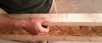
When making box-shaped structures, first fillet welds 1, 2, 3 of the side walls are made, then the walls are welded to the bottom with seams 4, 5, 6 and 7. The welding ends with vertical seam 8. The specified welding order gives the least warping of the product. When the thickness of the metal being welded is more than 5 mm, V- or X-shaped cutting of edges is used.
Gas welding of small diameter pipes (up to 100 mm) is widely used, especially during the installation of heating and hot water supply systems, water pipelines, gas pipelines and other tubular structures.
Pipes are most often butt welded, since butt joints require the simplest preparation of edges, the least amount of time and consumption of flammable gas.
When the pipe wall thickness is up to 5 mm, welding is carried out without cutting the edges, and the joint is assembled with a gap of 1.5-2 mm. When welding pipes with a wall thickness of more than 5 mm, one-sided cutting of the edges is used at an angle of 70-90°, leaving a bluntness of 1.5 to 2.5 mm. Blunting is necessary so that during welding the edges do not melt and the molten metal does not flow into the pipe.
Figure 1 - Sequence of welding of a box-shaped product
Depending on the purpose of the structure, other methods of joining pipes are used - without beveled edges with a backing ring, with a socket and an insert ring.
Before gas welding, the pipes are aligned so that their axes coincide and are tacked. Centralizers and other devices are used to center pipes. Gas welding of pipes can be performed using both left and right methods. If the pipe can be rotated, then welding is carried out in the lower position. A fixed joint is welded in all spatial positions, which is the most difficult for the welder.
When gas welding pipes of large diameter (300 mm or more), welding begins from any point on the circumference of the pipe and is performed in four separate sections, as shown in figure a. When welding pipes with a diameter of 500-600 mm, welding can be carried out simultaneously by two welders. First, the upper part of the pipe is welded in sections 1 and 2, then the pipe is turned and sections 3 and 4 are also welded at the same time. If the pipe cannot be rotated, then sections 3 and 4 are welded in the order shown in the figure, with dotted arrows.
a - 200-300 mm, b - 500-600 mm, c - welding without rotation
Figure 2 - Sequence of welding large diameter pipes
During repair work, it is often necessary to weld cracks that occur in welds and in the base metal. When welding cracks, it is necessary to pre-drill the ends of the crack so that when heated, the crack does not spread further.
In low-carbon steel parts, the ends of cracks do not need to be drilled. When the metal thickness is over 3 mm, the crack is cut from one or both sides, depending on the thickness of the welded product. The crack is welded from the middle to the edges. If the length of the crack is more than 500 mm, then welding is carried out in sections using the reverse-step method. The edges of the crack must be cleaned to a metallic shine before welding. Small cracks are welded in one direction.
When repairing closed containers containing flammable substances, it is necessary to thoroughly clean the container from the remains of flammable products, since their remains can form explosive compounds with air. The container is washed with hot water and caustic soda.
When welding vessels containing petroleum products, G. A. Medvedev’s method is used, in which the vessel is filled with exhaust gases from internal combustion engines. Gases are supplied continuously during the welding process. Welding is carried out in the usual way using filler wire. The burner flame is ignited and extinguished away from the container being brewed.