A lift for a router, which can be purchased in a serial version or made by hand, is a device that allows you to improve both the quality and accuracy of processing performed with hand-held power tools.
The results of the latter strongly depend on how accurately and confidently the user manipulates such a device.
In order to minimize the influence of the human factor on the results of processing performed with a manual milling cutter, special devices were developed.
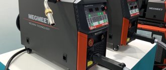
Homemade elevator for a manual router, made of plywood and timber
One of them is a mechanized lifting device for milling power tools, which, in full accordance with its functionality, is called an elevator. As mentioned above, such a device can be purchased in a serial version, but it will not be cheap, so many home craftsmen successfully make it with their own hands.
Why is such a device needed?
A lift for a router, which ensures precise movement of a hand-held power tool mounted on it in a vertical plane, is necessary in many situations.
Situations in which the quality and precision of processing of wood products are of no small importance include decorative finishing of furniture panels, making technological grooves and lugs on elements of furniture structures.
The quality of processing in such cases will not depend on the experience of the master performing it and the firmness of his hands, but only on the accuracy of the device settings and the degree of its stability.
Even a person with good physical fitness gets tired when working with a hand router, the weight of which can be 5 kg or even more.
This directly affects the accuracy and quality of work.
In addition, the precision of processing that a manual milling machine mounted on an elevator can provide cannot be achieved when manipulating a power tool manually.
For most routers, standard adjustment when installing the tool in the table becomes simply inconvenient
The need to invent such a useful device as a lift for a router was driven by the fact that the variety of types of decorative finishing of wood products has expanded significantly, the technological methods for processing this material have become more complex, and the requirements for the accuracy of its implementation have also increased.
All of the above factors require that manual milling electrical equipment combine high mobility of its working body, as well as the accuracy of the movements it makes.
It is these requirements that are fully met by a lift for a router, with the help of which the power tool used is quickly raised and lowered to the required height above the workbench, and also held at a given level for the required amount of time.
The convenience of using a milling elevator also lies in the fact that it is not necessary to install a power tool on such a device each time. This helps to both simplify the production process and increase its productivity.
On what principle does the lift for a router work?
In order to raise or lower a manual router using a router lift, you can use a crank, lever, or any other lifting mechanism of a suitable design. This functionality, which the router lift has, provides:
- quick and accurate setting of the dimensions of grooves and other relief elements cut on the surface of a wooden workpiece;
- Possibility of quickly replacing tools in the milling cutter chuck.
If we summarize the design options for the most used models of milling elevators, we can describe the operating principle of such a device as follows:
- A support plate for the router, which is made of a sheet of metal or textolite, is mounted on a work table or workbench.
- Two racks arranged in parallel are fixed to the support plate.
- The manual router itself is mounted on a special carriage, which has the ability to move freely up and down along the racks installed on the support plate.
- The carriage with the milling power tool installed on it and the entire elevator move to the required distance due to the fact that they are acted upon by a special pushing device.
The use of metal parts in the design will significantly increase the accuracy of the homemade milling elevator
Let's consider the basic requirements that should be followed when planning to upgrade the router with your own hands using a lift.
- The frame for placing the router and all other structural elements of such a device must have high rigidity. Compliance with this requirement will not only improve processing accuracy, but also make the user’s work safer.
- The lifting system with which such a device is equipped must be designed in such a way that it can ensure not only the quick removal and installation of the router used, but also the prompt replacement of the milling heads on it.
- The working stroke of the milling elevator should not be made too large; it is quite enough if the working head of the power tool moves within 50 mm. This is quite enough for high-quality performance of most technological operations.
- When developing drawings, it should be ensured that the working head of the power tool used can be rigidly fixed in a given spatial position.
The simplest milling lift can be made from a jack or a tubular clamp
What is needed to make a milling elevator
In order to make your own milling lift, you must prepare the following set of consumables, tools and technical devices:
- directly the manual router itself, from which it is necessary to remove the handles;
- electric drill;
- standard car jack (if the lifting mechanism of the device is of the jack type);
- sheet of metal or textolite;
- wooden blocks of square section;
- aluminum profile;
- sheets of plywood and chipboard;
- guides made of metal;
- threaded rod;
- a set of screwdrivers of various types and sizes, wrenches and pliers;
- drills of various diameters;
- bolts, screws, nuts and washers of various sizes;
- epoxy adhesive;
- square, ruler, measuring tape.
In general, only the motor and stands can be used from the router, especially if the tool does not have high accuracy of movement along the telescopic guides
Possible design options for the device
Today, home craftsmen have developed many designs of milling elevators, but the most popular and, accordingly, worthy of attention are two options for manufacturing such a device:
- a lift for a hand router, driven by a car jack;
- a device whose structural elements are a support disk, a threaded rod and a flywheel disk.
What is needed to make a milling elevator
In order to make your own milling lift, you must prepare the following set of consumables, tools and technical devices:
- directly the manual router itself, from which it is necessary to remove the handles;
- electric drill;
- standard car jack (if the lifting mechanism of the device is of the jack type);
- sheet of metal or textolite;
- wooden blocks of square section;
- aluminum profile;
- sheets of plywood and chipboard;
- guides made of metal;
- threaded rod;
- a set of screwdrivers of various types and sizes, wrenches and pliers;
- drills of various diameters;
- bolts, screws, nuts and washers of various sizes;
- epoxy adhesive;
- square, ruler, measuring tape.
In general, only the motor and stands can be used from the router, especially if the tool does not have high accuracy of movement along the telescopic guides
Elevator for router – Master4dom.ru
A hand router is an indispensable power tool in carpentry. With its help, you can quite easily and quickly perform operations such as milling grooves on workpieces, processing edges, milling profiles of frames and panels. But some operations are difficult to perform while holding the router in your hands.
For example, it is more convenient to mill frame profiles on a milling machine. The cost and dimensions of such a machine are not always acceptable, and if you already have a manual router, you can install it in a table. You can read an example of such an installation in this article: “Sawing and milling table.”
- If you limit yourself to only such an installation, then the functionality of such a table is very limited. In order to unlock the full potential of the milling table, the following conditions must be met:
- — ensure smooth lifting and lowering of the router for precise alignment of the cutter over the table.
- — make a parallel stop with the possibility of recessing a cutter into it to set the milling width and clamps with which the workpiece will be pressed against the table and the stop.
- — perform high-quality removal of chips from the cutter.
In order to ensure smooth raising and lowering of the router, it is necessary to build an “elevator” for the router. The simplest lift for a router is an ordinary car jack. The smoothness of the jack's rise allows you to accurately set the reach of the cutter above the table.
In order not to block the ventilation holes, as well as to ensure uniform pressure from the jack on the rods along which the router moves and thereby avoid jamming, I decided to make a U-shaped frame from slats with a section of 20 by 45 mm of the same height, giving the ends of the slats such a profile so that they wrap around the base router handles. In this case, there is no need to fix the router to the frame. The router's own weight holds it on the frame.
I fixed the frame to the jack with M6 bolts, then installed the jack on a pre-prepared base under the router. To make it easier to raise and lower the router on the jack, I installed a small handle through the furniture corner.
A parallel stop for a router, in addition to its direct purpose - to ensure the passage of the workpiece along the cutter, should also provide the ability to change the depth of the cutter's reach by partially recessing the cutter into the stop and removing sawdust from the cutting area. It would also be useful to be able to fix the stops or the upper clamp on the rip fence using a T-track.
The parallel stop was made from 18 mm thick plywood. It consists of two parts measuring 63 by 10 cm, two 9 by 6 cm and two 22 by 6 cm. And also one beech strip measuring 22 by 1.5 by 1.2 cm. In the first two parts I cut out a profile for recessing the cutter . I fixed these parts at an angle of 900 with self-tapping screws. From the side of the formed corner I installed two parts 9 by 6 cm.
How to do it yourself?
To make your own lifting mechanism, you will need tools, materials, instructions and drawings. Home craftsmen have become accustomed to assembling such mechanisms from various elements. The simplest option for making a homemade milling elevator is from a jack and a drill.
Before starting work, you should prepare all the necessary materials and tools:
- manual router - you must first remove the handles from the tool;
- a classic jack used to service a car;
- electric drill for drilling holes in wood and metal;
- wooden beam with a square cross-section;
- metal sheet or textolite;
- screwdrivers, wrenches and pliers;
- metal guides;
- a set of drills of various diameters;
- threaded rod.
There are several of the most practical and noteworthy options for making a do-it-yourself milling elevator.
From the jack
The basic principle of operation of such a device is to regulate the position of the milling head using a car jack built into the lifting structure.
To make your own jacking router, you need to follow the instructions.
- A box is made from plywood with a thickness of at least 15 mm, which is attached to the lower plane of the workbench tabletop. This structural element will simultaneously perform several functions: protective and supporting.
- A router and a jack are placed inside the box. In this case, the hand tool should first be attached to the moving part of the lifting mechanism. The base of the jack is screwed to the bottom wall of the box, the router is screwed to the workbench tabletop. In this case, a hole should be made in the table itself. The router head will go through this slot.
- The metal support plate will move along fixed axes.
This type of lifting mechanism is the simplest, but at the same time very convenient to use. If desired, the design can be improved by installing an electric drive, which will further mechanize the work process. But in this case, the cost of the equipment will increase significantly.
With threaded rod
To make this lifting mechanism design, you will need a small threaded rod, a support disk and a flywheel.
To manufacture equipment, follow the algorithm of actions.
- Cut a circle out of the board. This structural element will serve as a support for the hand router.
- In the center of the wooden circle, make a hole with a diameter of 1 cm, into which a threaded rod with a length of 5 cm will be inserted.
- The stud is secured to the support circle using nuts and washers.
- The bottom of the stud attaches neatly but securely to the flywheel.
- A flange nut is inserted into the bottom of the hole, which plays the most important role: controlling the functioning of the entire lifting mechanism.
This design can also be improved by using a device that allows the movement of a hand router. You can easily turn your equipment into a functional and practical 3D milling machine.
With chain drive
Making a lift of this design will require a little more time and effort. However, you will be pleased with the result. It provides precise and uninterrupted operation for smooth adjustment of hand tools.
There are several elements in the design.
- A frame on which the lower and upper milling inserts are connected using pins. They play the role of the main working mechanism and ensure smooth movement of the moving element.
- Moving insert. Its role is best fulfilled by a two-layer plate, in the interlayer of which there are nuts with sprockets installed on them. A standard bicycle chain is quite suitable for this design.
- Chain tension mechanism. The most practical is to use a metal crescent in this part of the device. This structural element must have tension on one side and at the same time move freely in the opposite direction. An eccentric is installed in the immediate vicinity of it, the rotation of which will weaken or strengthen the pressure on the crescent. This will ensure reliable chain tension.
Manufacturing a milling elevator of this design will provide you with reliable and convenient equipment that will not let you down at the most important and crucial moment.
How to make a lift for a router in a workshop
When working on a milling table, it is very convenient to adjust the reach of the cutter “without leaving the cash register,” as they say. For this purpose, you can use a lift (elevator) for the router, which you can make yourself.
In this case, to make the milling table and the lift itself, the author uses laminated plywood, wooden blocks, a couple of steel cables, and some other materials.
The author makes a milling table from wooden blocks and a sheet of plywood. You need to cut a rectangular hole in the center and also make a lid with a round hole.
Main stages of work
From pieces of ordinary plywood, cut to size and furniture guides, the author assembles the main part of the lift for the router. You will also need a piece of threaded rod (or a screw of the appropriate diameter).
Next, you will need to cut another rectangular blank from laminated plywood with a hole for the back of the router. Then we take two cables and we can begin assembling the lifting mechanism.
At the last stage, the entire structure and a manual router are installed under the table. The result is a simple elevator that will help make work more comfortable.
For details on how to make a lift for a router with your own hands in a home workshop or garage, watch this video.
Rate this post
Source: https://sdelairukami.ru/kak-sdelat-podemnik-dlya-frezera-v-masterskoj/
Elevator for a router: several DIY options
A lift for a router, which can be purchased in a serial version or made by hand, is a device that allows you to improve both the quality and accuracy of processing performed with hand-held power tools. The results of the latter strongly depend on how accurately and confidently the user manipulates such a device. In order to minimize the influence of the human factor on the results of processing performed with a manual milling cutter, special devices were developed.
Homemade elevator for a manual router, made of plywood and timber
One of them is a mechanized lifting device for milling power tools, which, in full accordance with its functionality, is called an elevator. As mentioned above, such a device can be purchased in a serial version, but it will not be cheap, so many home craftsmen successfully make it with their own hands.
This is interesting: How to make a homemade frame for an angle grinder
Make a lift for the router yourself, or buy a ready-made one? Let's answer this question
When using a manual router installed in a stationary table, two questions arise:
- How to adjust the depth of immersion (extension) of a cutter.
- How to quickly change replacement tips.
Unscrewing the tool from the plate every time is too troublesome. In addition, a statically mounted router works in the workpiece only at a fixed depth.
This problem is solved by installing a height-adjustable suspension on the router. And once you were able to make a full-fledged milling table, installing an elevator of your own design is not difficult at all. In addition, a self-made device is developed taking into account all the requirements of the master, even those that are not provided for by the factory device.
Why do you need a lift on the milling table, and is it possible to do without it?
This useful device is called the third hand of the master. Those who have tried a milling cutter with a microlift are finding new applications for it:
- Maintaining a power tool is not difficult, as is quickly changing cutters.
- You can change the cutter reach height in a matter of seconds, and most importantly – safely.
- You can change the immersion depth “dynamically”, simultaneously with the movement of the workpiece on the table. This expands creativity.
- Due to the fact that you no longer regularly dismantle the tool for maintenance, the plate and its fasteners are subject to less wear.
Buy or make it yourself?
There is a wide choice of offers on the power tool market. Industrial microlifts look good and work without failures, but their cost is the same as that of a new router. True, the device is quite well equipped. The kit includes rings for the copy sleeves, and a very high quality mounting plate.
Industrial microlift for a router with a set of copy rings
All that remains is to electrify the device - and you can get a CNC machine. There is only one drawback, but it outweighs all the advantages - the price itself. Therefore, for occasional home use this is an unaffordable luxury. So our Kulibins make whatever they can. However, there is a lot to learn from them.
There are quite primitive lever-type designs
Homemade elevator design with a lever mechanism
This technique even allows the use of a “foot” drive.
It is not suitable for precise reach settings, however, with the help of such a mechanism, you can raise the router to the working position with one movement, and just as easily lower it to change the attachment or service.
This elevator has a fairly long stroke; it does not allow for adjustable milling. Materials for manufacturing are literally lying underfoot, the cost tends to zero.
Using a Screw Adjuster
Another example of a homemade elevator for a router
The design is more advanced and allows relatively precise adjustment of the reach. However, using such a microlift is inconvenient; to rotate the handle, you need to crawl under the table, and then make a control measurement of the height of the cutter. But the reliability is high, and production does not require expensive materials. Such an elevator can be made “by eye” without using drawings.
Do-it-yourself table for a router: with drawings and production
A hand router is a unique tool that greatly facilitates the process of making wood products. It is used not only to create technological connections, but also during decorative processing. The main advantage of a manual router is mobility, the ability to work regardless of the availability of a workshop.
Why do you need a router table?
Professional craftsmen do not ask this question; they have separate milling machines. This can be not only woodworking equipment of industrial series, but also special machines for household use. As a rule, they are complex mechanisms that have a circular saw, jointer, milling cutter and drilling machine in various combinations on one frame.
Ordinary hobbyists do not need to buy such equipment; an ordinary hand router is enough for them. But situations arise when many people think about making a table for a router. Why?
- It is not possible to mill by hand, the tool does not move in a straight line, the surface of the parts is wavy. You have to go through one place several times, and this has a negative impact on the final quality.
- The need to mill long workpieces - only on a table can this operation be performed in just one pass.
- There is a need to work on cutters with a complex profile; the manual method does not provide the required surface cleanliness.
It should be noted that not all technological operations can be done on a table; there are some that can only be performed with a manual router. For example, it is impossible to mill profiles with a closed contour located in the center of the workpiece on the machine.
Prices for a linear series of milling cutters
A professional craftsman spares no expense in purchasing the most modern and reliable equipment - such investments not only pay off, but also bring significant profits.
This is his permanent job and main income, and the higher the labor productivity, the less unproductive loss of materials and the better the quality, the more profit the master has. There is no point in buying expensive machines and equipment for novice craftsmen; one hand cutter is enough for them.
Accordingly, the machine must be made in such a way that the cutter can be quickly removed at any time and can be used in normal mode. Another requirement is that the table should be as simple to manufacture as possible. You can do it with your own hands and using the simplest set of tools that non-professionals have.
Due to such requirements, we will not consider options for complex tables; only master carpenters can make them.
In addition, most projects require reworking a hand router; after reconstruction, the tool can no longer be used in manual mode; you need to buy a second copy.
It is economically unprofitable to waste time and financial resources on making a table for a router just to use it for a few hours a year, and for ordinary, more frequent work, buy another manual router.
Manufacturing materials
The correct choice of table materials determines its service life and the quality of milling of parts. What materials are recommended to be used for these purposes?
Types of tables by material of manufacture
Type of table for a router Brief description of physical and operational characteristics
| Plywood | Most often used. In terms of cost and performance indicators, the most suitable option, you just need to buy special plywood, its veneer is glued with especially strong two-component polymer adhesives. This type of plywood is not recommended for use during furniture manufacturing; the amount of phenols and formaldehydes released into the air exceeds permissible standards. But in the workshop the material can be used without fear. But in terms of strength, this type of plywood confidently occupies a leading position, and this is the most important characteristic. |
| Metal | A metal table has been in use for many decades, but to manufacture it you must have practical experience in welding work. Another problem is that some parts need to be sharpened; almost no one has a lathe at home, so you have to turn to specialized companies. |
| Combined | Highly recommended for use. Some of the most loaded elements are made of metal, the rest can be wooden. By the way, the table does not have to be made from scratch - after a little reconstruction, ordinary prefabricated/collapsible small kitchen tables fit perfectly. These were once in every apartment and today are still used in utility rooms. |
You can also use glued furniture panels made from natural lamellas; they do not change their size with fluctuations in relative humidity, but such a table for a router will be very expensive. It is strictly forbidden to use natural boards due to constant warping in one direction or another, which has an extremely negative impact on the quality of milling.
We will give step-by-step instructions for making two simple, but very functional, tables for a router. The dimensions are given only in general terms; the specific ones depend on the type of hand router, and there are a huge number of them available. Each model differs in several parameters that must be taken into account during work.
milling table and lift for the router
To get a professional result you need a router table and a lift, router, bit and they don't have to cost a fortune or weigh a ton. My version of the milling table is 25 mm thick plywood, which does not require a cabinet or cabinets below and is attached to the workbench with clamps. The project has an adjustable lift and a stop with a dust collector.
How to make a router table and a router lift
Milling table and elevator, these are the first works on the milling table and they consist of preparing a place for the router and two metal rods for the elevator.
Notice in the photos that instead of mounting the router on removable plates, I use two metal guide rods that come standard with the tool.
The base of the router is installed in a deep niche; the depth of the niche is equal to 3/4 of the thickness of the base. The grooves for the rods match the size
diameter of the rods. Having installed the router in the grooves on the table, secure it to the table using mounting blocks: bolt, washers and nuts. If your router does not have guide rods, then you will need to make changes to how the router is attached to the base.
Assembling the router lift
The router lift consists of an open frame mounted on one of the mounting blocks. A nut is installed on the frame through which the threaded rod rotates using a round disk (Fig. 5,6). The manufacture of the elevator begins with the manufacture of the frame and (positions 3, 4, 5, 6 and 10) (Fig. 4). In order to prevent rotation of the elevator clamping bar (Fig.7)
around the router (position 10) (Fig. 4), four screws are screwed into the upper part of the router and they are aligned with the holes in the elevator clamping bar.
Creating a stop
Making the stop is not difficult. Prepare the vertical and horizontal bases (positions 11 and 12) (Fig. 4). Using a drill, jigsaw or router, form slots in the bases (Fig. 9). Make four triangular strips (item 13) (Fig. 4) to stiffen the stop.
You are ready to assemble the stop, connect the prepared parts together (Fig. 11). The ends of the auxiliary pads (item 14) (Fig. 4) for the stop, cut at an angle of 45°. Drill through holes for bolts in each trim.
Install the pads on the vertical support base and secure with bolts, washers and nuts (item 17) (Fig. 4). And lastly, the dust collector (position 15) (Fig. 4) is needed or not - it’s up to you to decide. Cut it to size, bevel the ends for a tighter fit.
Cut a hole in the dust collector bar that matches the diameter of the hose nozzle. Connect the dust collector bar and the stop using the curtain (position 16) (Fig. 4).
At the final stage
Many people write that for precision machining, each cutter must use a hole corresponding to the diameter of the cutter. A large diameter cutter is used, which means it requires a large hole in the base of the table.
If desired, make insert rings of different diameters, although these rings are optional and you can work with one large hole drilled in the base of the table (Fig. 4). Basically, in a hole with a diameter of 32 mm. will accommodate cutters of different diameters.
I note that in the process of processing products without insert rings, no large flaws were noticed that could not be eliminated with sandpaper. At the final stage, carefully sand the parts and apply several layers of durable coating.
Source: https://woodjig.net/frezerniy-stol-i-lift-dlja-frezera/
DIY milling table: drawings and diagrams
When milling any parts using a manual milling machine (we don’t remember industrial machines, they have completely different dimensions and capabilities), it is necessary to move the device along the surface of the stationary part.
If the router has guides for the task of moving, the task becomes a little easier, but their length does not usually allow working with any large parts. Therefore, there is a need for a special milling table.
What is a milling table?
This is a fairly large plane, made of durable material that can withstand loads well. The horizontality of the surface and the absence of unevenness are important - otherwise the work will be very difficult. Typically, the countertop is made of wood or its derivatives.
This is due to the fact that wood (plywood, chipboard and similar materials), produced in the form of a slab, already has a flat and smooth surface and dampens vibrations well during operation. A cutout (hatch) is made in the tabletop, and a manual router is attached to the bottom.
Standard models provide for fastening to a horizontal plane, and which side to do this on – top or bottom – is left to the user’s discretion.
In addition to the tabletop, supports are needed - strong, stable, capable of withstanding significant loads. Suitable for them are massive timber (section from 40x40 mm), flat panels, metal racks or a welded metal frame (assembled on corners and plates).
A metal plate placed on the tabletop at the cutout location
It protects wood from excessive loads and mechanical damage, and simplifies work with cutters. Another important advantage is the reduction in the thickness of the table, that is, providing a larger working stroke of the cutter compared to a thick tabletop.
When using a plate with a thickness of 2...3 mm, you can use almost the entire stroke of the cutter (35...70 mm, depending on the model), and for a tabletop with a thickness of 20 mm, all these millimeters are “subtracted” from the possible processing depth.
The plate is attached to the tabletop with screws (self-tapping screws) and must be quickly removed if necessary, so it is better to reinforce the mounting sockets with nuts or other elements with an internal thread of a suitable diameter driven into the wood.
In this case, the router itself is attached from below to the plate, and not to the tabletop, and can rise with it - this is convenient if you need, for example, to replace the router with an electric jigsaw or drill for drilling numerous holes in a long part.
The plate for a router for a table with your own hands must be made of high-quality, preferably non-rusting steel, rigid and durable, at least 2 mm thick (depending on the weight of the router and the properties of the steel).
The hole for the cutter must be processed along the edges, since the cutters will have to be changed quite often and it would be stupid to remove the device for this each time. I feel sorry for my fingers; they don’t need wounds from metal burrs.
Guides
Designed for uniform, smooth displacement of the workpiece along a given direction. The simplest guides are a flat beam screwed/nailed/glued to the tabletop at the required distance from the cutter. A more “advanced” option is guides with the ability to shift and/or rotate.
The easiest way to do this is to fasten the guide to the table with clamps, but this option does not guarantee a strong fastening - under the influence of vibration, the threads on the clamps “relax” and the guide begins to move out of the given position.
Therefore, it is better to provide a number of fastenings for the guides - with the ability to move the guide relative to the cutter axis, with the ability to rotate by a given degree.
By gluing (cutting) markings in the form of a regular measuring tape along the side edges of the tabletop and providing latches at the ends of the longitudinal guide for tight fastening, you can quickly change the distance from the working tool to the extreme plane of the workpiece.
You can also make a parallel stop for a milling machine with your own hands using screw fastenings, but then you can only move it with a certain pitch corresponding to the pitch of the threaded holes for fastening in the tabletop.
Another convenient option is to fasten aluminum (steel) guides along the end sides of the tabletop and equip the parallel stop with sidewalls with screw fastenings for these guides. Then smooth movement is possible.
If you make a horizontal insert from an aluminum (steel) profile with vertical stops moving along it in a displaceable guide, it will be easier to secure the workpiece.
Advantages
- No longer does it require you to crawl under the table to adjust the bit height, but it also makes fine-tuning much easier. Instead of adjustment under the router table, this model has the ability to adjust from above using a handle. This significantly speeds up work and allows you to achieve maximum accuracy. The lift also allows you to significantly simplify the process of replacing cutters.
- Designed so that every full revolution of the dial moves the carriage and your bit exactly 1.588mm, although adjustments of up to 0.05mm are possible. The built-in micro-adjustment dial can be reset at any time to set the dial to the base setting so you can make precise adjustments to cutter height and get the exact same setting every time you repeat a job.