Calculation of deposited metal during welding
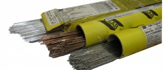
Weld metal is a filler material that is deposited onto the base material or introduced into the pool. This term is used when using thermal types of welding equipment in industry. For automatic and semi-automatic devices, wire of various types is purchased, differing in the design of the rod and composition, the presence/absence of alloying components.
There are 3 groups of steel wire:
- with a large volume of alloying components;
- with a minimum amount of alloying components;
- with carbon, titanium, chromium, nickel, silicon, manganese.
Each group, based on its composition, is divided into many subgroups.
By design, steel wire can be:
- solid;
- powder (in the form of a tube);
- activated (5-7% powder in the form of wicks in a continuous structure).
Aluminum and copper wires and powder additives are available. Each welding method has its own type of additive and its consumption rates, which are developed based on many years of experience.
Calculation of the mass of deposited metal is most often used when determining the time required to carry out a certain amount of work: manufacturing a product, creating a meter of welded joint. Although it is most convenient to express the time in minutes required to create a meter of weld, minutes are sometimes used to deposit a kilogram of additive.
The amount of filler material welded onto the surface or introduced into the bath is closely related to the standards developed for wire consumption. If you know how much additive is needed to create a meter of welded joint, and how many such joints are planned to be created over a certain period of time, then it is easy to determine the weight of the wire stock. When calculating, it is necessary to take into account the characteristics of the additive and the volume of waste.
Formula for calculating the weight of the molten additive
Formula for calculating the weight of deposited metal per meter of welded joint:
L(m 2 ) – cross-sectional area;
q(g/m 3 ) – specific gravity of the additive (7700-7900 – steel, 2640-2700 – aluminum, 8200-9100 copper and alloys);
T=1, if calculates flow per meter.
This formula is correct if welding is performed with the base material in a horizontal position. In other provisions, the formula is supplemented with a coefficient:
- 1.05 – the connection is inclined, formula:
- 1.1 – the connection is located vertically, formula:
- 1.2 – connection on the ceiling, formula:
The seams can be double-sided, corner, T, V-shaped, X-shaped (GOST 5264 - 80), so problems may arise when calculating the cross-sectional area. If the seam connects two flat parts without bevel of the edges, then you need to multiply the width by the depth (thickness of the material being welded). If there is a bevel of more than 30 degrees, the result obtained is multiplied by 0.75. For corner and T joints, the result is divided by 2.
The entire area can be divided into several simple parts, the area of which is easily calculated. If the connection is X-shaped, the area for each side is calculated, then the results are summed. Tables for various types of seams are available on the Internet, allowing you to avoid difficult calculations.
The weight of the additive required for operation in a certain period of time can be found out by adding 2-6% (natural losses) to the result obtained. The percentage depends on many factors:
- composition of the material being welded;
- wire diameter;
- presence/absence and type of gas;
- welding method;
Table of deposited metal during welding
- technical characteristics of the equipment.
Each household and enterprise decides independently how to determine the mass of deposited metal during welding.
Cross-sectional area of deposited weld metal formula
A seam (weld) is a place where different elements of one structure are fused.
A seam section is an image of a figure formed by cutting a seam with a plane in the transverse direction.
Formula for calculating the cross-sectional area of a seam:
a – base of the seam; h – seam height.
See also the article about all geometric shapes (linear 1D, flat 2D and volumetric 3D).
You can quickly perform this mathematical operation using our online program. To do this, enter the initial value in the appropriate field and click the button.
This page provides the simplest online calculator for calculating the cross-sectional area of a seam (cross-sectional area of a seam), if the base of the seam and its height are known. Using this calculator, you can calculate the cross-sectional area of a weld in one click (cross-sectional area of a weld, cross-sectional area of a weld, cross-sectional area of a weld metal).
Regardless of the welding method, the following conditions must be observed to ensure a welded joint with the required workability:
1) special preparation of edges;
2) high quality of preparation and assembly for welding;
3) mandatory cleaning of surfaces that are being welded.
The welding mode is the set of basic characteristics of the welding process, which ensure the production of welds of the specified size, shape and quality.
The first condition for calculating welding conditions is to obtain seams with optimal sizes and shapes, which provide high technological strength and high performance characteristics.
The main parameters of arc welding include: welding current Iw, arc voltage Ud and welding speed Vw. Each of these parameters, both individually and in combination with others, affects the amount of heat input and, therefore, the geometric dimensions of the weld, the penetration shape coefficient, the weld shape factor and the participation of the base and electrode metal in the formation of the weld.
Optimal welding mode parameters provide the required geometric dimensions of the welds and the necessary ratios between the base and electrode metal, at which the specified mechanical properties of the weld metal are achieved.
Seam No. 1:
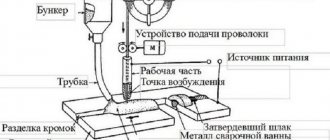
Welding method: semi-automatic welding in shielding gases;
Seam type: T1-?5 tee, one-sided, without beveled edges;
Steel grade: st3sp5,
Figure 4.1. – Cutting edges for weld T1 according to GOST 14771-76
We determine the area of deposited metal using the formula:
Fн=
Fн
We set the diameter of the electrode wire de.pr. = 1.6 mm, current density j = 175 A/mm 2
The strength of the welding current when welding in a shielding gas environment is determined depending on the diameter of the electrode that we initially set and the permissible current density:
For the accepted electrode diameter and welding current, we determine the optimal arc voltage:
.
The welding speed can be determined by the formula:
,
where is the deposition coefficient, determined depending on the welding current and wire diameter;
g=7.8 – density of the deposited metal;
FН1р – cross-sectional area of the deposited metal for a given pass, cm 2.
The electrode extension is found according to the formula:
Choose L = 18 mm.
The wire feed speed is determined by the formula:
Seam No. 2:
Welding method: semi-automatic welding in shielding gases;
Seam type: T7, tee, one-sided, with a bevel of one edge, with an underwelding seam;
Steel grade: st3sp5;
Figure 4.2 – Cutting edges for seam T7 according to GOST 14771-76
1. Determine the leg of the seam using the formula:
k = 0.15 * s – 0.5s = 0.15 * 20 – 0.5 * 20 = 3 – 10mm,
We take k = 5 mm
2. Determine the area of deposited metal:
The area of deposited metal during semi-automatic welding is 40-50 mm 2. Select Fн = 40 mm 2.
3. Area of deposited metal of the weld and root weld:
Structurally we take =10 mm 2.
4. Knowing the total cross-sectional area of the metal deposited during the first and subsequent passes, we determine the number of passes:
We set the diameter of the electrode wire de.pr. = 1.6 mm, current density j = 175 A/mm 2
5. Determine the strength of the welding current:
6. Determine the optimal arc voltage:
.
7. Determine the welding speed:
,
where is the deposition coefficient, determined depending on the welding current and wire diameter;
g=7.8 – density of the deposited metal;
FН1р – cross-sectional area of the deposited metal for a given pass, cm 2.
8. Electrode extension is found according to the formula:
Choose L = 18 mm.
9. Determine the feed speed of the welding wire:
We determine the welding modes for performing the underweld and root welds:
1. Determine the current strength:
The current strength should be less than when welding the main seam to avoid burn-throughs.
2. Determine the arc voltage:
3. Determine the welding speed:
4. Determine the feed speed of the welding wire:
Seam No. 3:
Welding method: semi-automatic welding in shielding gases.
Seam type: T6, T-joint, one-sided, with one edge beveled.
Steel grade: st3sp5.
Figure 4.3 – Cutting edges for seam T6 according to GOST 14771-76
Calculation of the weight of the deposited additive for a weld length of 1 m
Weight of deposited metal when welding a meter of ordinary steel with a semi-automatic machine on a horizontal surface:
If the seam is on the wall:
If the seam is on the ceiling:
But it is impossible to get an accurate result using this formula or table from the Internet, especially if the project is large and important. It is necessary to involve a specialist who has licensed programs from the relevant departments. Design organizations can also help. There are similar programs on the Internet, and you can download them completely free of charge.
Read also: Operating principle of the hydraulic bottle jack
The program is easy to use. After entering the initial data, the result appears in the last window.
Content:
To determine the cost of welded products, it is very important to correctly calculate the consumption of materials during welding work. In addition, the quantity of required electrodes, welding wire, fluxes, shielding gases and other consumables must be known in order to ensure continuity of the work process by creating a sufficient supply of them in the warehouse.
The calculation of the required amount of materials for welding is carried out on the basis of existing standards for their consumption when using a particular welding method.
The consumption rate of welding materials is the amount required for the complete production of a welded product, taking into account all losses and waste. This standard includes the consumption of materials at all stages of the technological process associated with welding, namely during preparatory work (making tacks), conducting the welding work itself, as well as possible subsequent correction of the structure.
For each type of weld and each welding method, there are specific material consumption standards. In addition, when determining the amount of required materials, the inevitable losses during welding are taken into account, and there is also a certain rate of such losses, which depends on the welding method used and its mode, the length of the seam and the complexity of the entire welded structure.
How to rationally organize a welder’s personal space and work?
The concept of standardization of welding work implies the organization of labor, as well as the workplace. The main objectives here are to increase the efficiency of the labor process and exchange production experience.
Labor productivity can be increased by properly arranging the welder’s workplace. All activities aimed at arranging the employee’s personal place must be prescribed in the SOT (scientific organization of labor) plans.
The welder's workplace must be equipped in accordance with all safety requirements. In addition, the welder must be comfortable doing his job; he must have quick and easy access to all necessary parts, tools, and consumables. This will significantly save time on any work.
Basic formulas for calculating the consumption rate of welding materials.
There is a certain regulatory formula that helps calculate the consumption of materials during welding work. This formula allows you to understand how many welding materials are required per meter of seam:
N – rate of consumption of welding materials per meter of weld
G – mass of deposited metal of a weld, the length of which is 1 meter
K – coefficient of transition from the mass of deposited metal to the consumption of materials for welding
And in order to determine the mass of deposited metal per 1 meter of weld (G), you can use the following formula:
F – cross-sectional area of the weld (in mm 2)
y – specific gravity of metal (g/cm3)
L is the length of the weld (it is equal to 1 meter).
The above formulas allow you to calculate the material consumption rates for a weld in the simplest position - the lower position. If welding work is carried out in a vertical or overhead position, then the resulting standard must be multiplied by a correction factor, which takes into account the peculiarities of material consumption at different positions of the weld:
- for the lower position of the seam this coefficient is 1.00
- for a semi-vertical position of the seam, a coefficient of 1.05 is taken
- with a vertical (horizontal) position of the seam, the coefficient is 1.10
- when the seam is in a ceiling position, the previously obtained norm is multiplied by a factor of 1.20.
Let's consider what features you should pay attention to when determining the required amount of specific welding materials - welding wire and shielding gas.
Components of standardization of welding work.
Standards for welding work in electric arc welding include such components as time, amount of work, output, etc.
The time taken to produce a particular unit becomes the time standard when performing electric arc welding. One kilogram of metal deposited during the welding procedure, one meter of welding unit, as well as one part made during welding will be the amount of work. Time standards are measured in minutes per meter. The production standard refers to the entire range of work completed within a certain time. This output is measured by the length of the weld (in meters) that was completed per working hour or shift.
Electricity consumption is also a very important unit, both from a technical and economic point of view. The units of measurement for electricity consumption are kilowatts per hour per kilogram of metal melted during the welding procedure.
How to calculate welding wire consumption.
In order to calculate the amount of welding wire that will be required for the manufacture of a welded structure, it is necessary to take into account the following parameters:
- If a semi-automatic welding method is used, the amount of welding wire depends on the following factors:
- characteristics of the metal being welded
- welding wire diameter
- features and technical characteristics of the welding equipment itself
- presence or absence of shielding gas.
- The consumption of welding wire can be calculated based on the mass of the entire welded structure - as a rule, the maximum amount of wire is equal to 1.5% of the mass of the welded structure.
- Also, the mass of the wire can be determined based on the mass of the deposited metal. This calculation method takes into account that the required wire weight exceeds the weight of the deposited metal by 2-6%.
Calculation of shielding gas consumption.
Correct calculation of the amount of shielding gas required for welding work makes it possible to achieve high quality and continuity of welding work in a shielding gas environment. The amount of gas required depends on what kind of metal is being welded:
- to weld an aluminum structure you will need 15-20 liters of shielding gas (argon) per minute
- welding a copper structure in a shielded gas environment will require 10-12 liters of gas per minute
- for magnesium alloys, 12-14 liters of argon per minute will be required
- when welding nickel alloys, 10-12 liters of gas per minute will be consumed
- titanium and its alloys require higher gas consumption when carrying out welding work - 35-50 liters per minute.
But for welding steel products, shielding gas is used more economically.
In order not to consume excess gas during welding, gas cylinders are equipped with a special regulator.
In conclusion, I would like to note that correct calculation of the consumption of materials for welding work makes it possible not only to provide the welder with everything necessary on time, but also to save costs on the production of welded structures, and therefore, reduce the cost of production and increase its competitiveness in the market.
Read also: How to best connect aluminum wire to copper
Home page » About welding » Electrode consumption, standards, tables, how to calculate
An important part of any production or construction process is accurate and competent planning of material consumption, which is carried out to draw up estimates and calculate financial costs. When erecting metal structures by welding, it is important to know not only the metal consumption, but also the required number of electrodes. A correctly performed calculation will allow you to find out the exact cost of the work, and the welding process will be carried out according to plan.
It should be noted that calculating the consumption of welding electrodes is relevant and in demand only during the construction of large facilities . The large scale of work requires an accurate determination of the volume of materials, which will be included in the construction estimate. For this purpose, the concept of “electrode consumption per 1 ton of metal structures” was introduced.
Electrode consumption, norms, tables, how to calculate
An important part of any production or construction process is accurate and competent planning of material consumption, which is carried out to draw up estimates and calculate financial costs.
When erecting metal structures by welding, it is important to know not only the metal consumption, but also the required number of electrodes. A correctly performed calculation will allow you to find out the exact cost of the work, and the welding process will be carried out according to plan. It should be noted that calculating the consumption of welding electrodes is relevant and in demand only during the construction of large facilities . The large scale of work requires an accurate determination of the volume of materials, which will be included in the construction estimate. For this purpose, the concept of “electrode consumption per 1 ton of metal structures” was introduced.
Parameters affecting flow
Before calculating the number of electrodes for welding, you should find out which indicators are of utmost importance:
- Weight of material deposited on the connection. The volume of this parameter should not exceed 1.5% of the total mass of the entire structure.
- Duration and depth of the weld.
- Total mass of surfacing per 1 m.p. connections. Electrode consumption rates per 1 meter of seam are reference indicators presented in VSN 452-84.
- Welding type.
Importance for calculating material quality
A welder, in accordance with his qualifications, has to work with a variety of materials. This significantly affects the standard welding time.
It is customary to distinguish several main groups, differing in the content of chemical components and purpose. For example, group M01 includes structural steel alloys with a carbon and low-alloy composition. The yield strength of these materials does not exceed 360 MP.
As the value of the number in the marking increases, the characteristics of the alloys improve. Thus, class M07 includes reinforcing steels intended for the manufacture of reinforced concrete structures. When calculating time standards for welding work, the quality of materials is of fundamental importance.
Theoretical and practical calculations
The consumption of electrodes can be calculated from a theoretical point of view using a large number of special formulas. Let's look at the most common ones.
The first method - by coefficient - is used to calculate the consumption of various welding materials, and not just electrodes:
H = M * K, where M is the mass of the structure being welded; K is a special flow coefficient from the directory, which varies in the range from 1.5 to 1.9.
The second method is based on calculations depending on the physical properties of the electrode and the metal structure . Allows you to determine the mass of deposited metal. Here the performer will need to know the reference data, and it is also necessary to measure the connecting seam:
G = F * L * M, where F is the cross-sectional area; L is the length of the weld; M is the mass of the wire (1 cm3).
Practical calculation involves carrying out test work. After their completion, the welder should perform the following actions:
- measure the cinder;
- take into account voltage and current;
- determine the length of the welded joint.
These data make it possible to determine the consumption of welding electrodes when welding structures with a seam of a certain length.
The contractor will be able to obtain accurate indicators only if the external data and the position angle during the main work are identical to those that were during testing. To avoid inaccuracy of parameters, it is recommended to carry out the experiment 3-4 times. This will allow you to obtain more accurate calculations than using theoretical formulas.
Using these methods, you can easily calculate the consumption of electrodes per ton of metal structures. However, you should remember that there is an error.
Method for determining the penetration area when welding with a consumable electrode
The invention relates to the field of welding production and can be used to assess the unevenness of metal melting along the length of the weld without resorting to its destruction. The method includes measuring the welding speed and deposition productivity, on the basis of which the cross-sectional area of the deposited metal is calculated. In this case, before welding, on the basis of technical conditions for the base and deposited metals, the content of chemical elements in them is determined, and after welding, the content of these same elements in the weld metal is determined, and the share of the base metal in the weld metal is calculated for each chemical element contained in it and calculate the average value ΨOS of the share of participation of the base metal in the weld metal, and the cross-sectional area FO of penetration of the base metal is calculated by the formula
FO=ΨOSFH/(1-ΨOS),
where FH is the cross-sectional area of the deposited metal, cm2. 3 ill.
The invention relates to the field of welding and can be used to determine the chemical composition of a weld during fusion welding.
There is a known method for determining the area of fusion of the base metal of a weld deposited onto a plate by arc welding with a consumable electrode, according to which a macrosection of the cross section of the weld is made, the boundary between the weld metal and the base metal is determined from the macrosection, the cross-sectional area of the weld and the deposited metal is measured, and the cross-sectional area of the molten metal is calculated. base metal, as the difference between the area of the weld and the area of the deposited metal (see N.L. Zaitsev et al. Calculation and experimental methods for assessing the configuration of welds. Modern problems of welding production. Collection of scientific papers. Chelyabinsk, SUSU Publishing Center, 2021, p. .168, Fig. 4).
This method is labor-intensive, as it requires the production of a macrosection and cannot be used directly on the product being welded, but only on control samples. The resulting value of the penetration area of the base metal characterizes only one specific section of the weld, not allowing one to judge the average values of the penetration area for the entire weld. This method is not applicable for most welded joints that have grooved edges and a gap between the welded plates and the exact value of the cross-sectional area of the deposited metal remains unknown.
There is also a known method for determining the area of penetration of the base metal of a weld in a joint with a gap and cutting the edges being welded, performed by automatic arc welding with a consumable electrode, by which the welding speed and the productivity of surfacing of the electrode metal are determined, the cross-sectional area of the deposited metal is calculated, a macrosection of the cross-section of the weld is made, and the microsection of the boundary between the weld metal and the base metal, measure the cross-sectional area of the weld and calculate the cross-sectional area of the molten base metal as the difference between the cross-sectional area of the weld and the cross-sectional area of the deposited metal (see A.A. Erokhin. Fundamentals of fusion welding. M .: Mechanical Engineering, 1973. P. 159). This method is adopted as a prototype.
This method is also labor-intensive, since it requires the production of a macrosection and cannot be used directly on the product being welded, but only on control samples. The resulting value of the penetration area of the base metal characterizes only one specific section of the weld, not allowing one to judge the average values of the penetration area for the entire weld. The method does not allow obtaining information about the degree of deviation of the cross-sectional area of the base metal penetration and, as a consequence, the heterogeneity of the chemical composition of the weld along its length.
In the proposed method for determining the cross-sectional area of penetration of the base metal of a weld made by automatic welding with a consumable electrode, by which the welding speed and the productivity of surfacing of the electrode metal are determined, the cross-sectional area of the deposited metal is calculated.
Unlike the prototype, before welding the content of chemical elements in the base and deposited metals is determined, after welding the content of these same elements in the weld metal is determined, the share of participation of the base metal in the weld metal is calculated for each chemical element according to the formula
where СШ is the content of the chemical element in the seam, %;
CH is the content of this element in the deposited metal, %;
CO - element content in the base metal, %
and calculate the average value of the share of the base metal in the weld metal for all elements, and the cross-sectional area of the base metal is calculated by the formula
where ΨOS is the average value of the share of the base metal in the weld metal for all chemical elements, %;
FH is the cross-sectional area of the deposited metal, cm2.
The technical result of the proposed method is that the cross-sectional area of the base metal is obtained without making a macrosection of the cross-section of the weld, by determining its chemical composition. This is possible due to the fact that the average value of the calculated share of the base metal in the weld metal for several chemical elements adequately reflects the value of the penetration area of the base metal, and the values of the chemical composition of the deposited metal are determined in a standard manner during certification or attestation of welding materials. The chemical composition of the base metal is given in the certificates for the batch of rolled products and is monitored during the incoming inspection of the properties of the metal at enterprises. Determining the content of the chemical composition of the base and deposited metals when welding critical structures is an integral part of developing the technology of their welding. Modern methods of spectral chemical analysis make it possible to quickly and with high accuracy determine the content of chemical elements in a seam, including at individual points along its length on the front and back surfaces of the seam. This allows the proposed method to be used without destroying the weld metal. Information about deviations in the cross-sectional area of fusion of the base metal along its length makes it possible to judge the stability and uniformity of the weld and take measures to improve the quality of welded joints.
In fig. Figure 1 shows a cross-section of a surfacing weld during arc surfacing on a plate with a consumable electrode; Fig. 2 - cross-section of a welded seam of a butt joint, made with a gap and grooved edges, in Fig. 3 - dependence of the melting rate of the consumable electrode on the arc current.
In fig. Figure 1 shows a cross-section of a weld obtained by making a macrosection of surfacing on a solid plate 1 of thickness S. It can be accurately divided into a cross-section of the base metal 2, area FO, and a cross-section of the deposited metal 3, area FH. The area of penetration of the base metal is determined as the difference between the cross-sectional area of the weld FSh and the cross-section of the deposited metal
Based on the measured areas FSh and FO, it is possible to calculate the share of the base metal in the weld metal
From formula (4) we obtain a formula for determining the area of penetration of the base metal FO, if the share of the base metal in the weld metal is known
In fig. Figure 2 shows a cross-section of a weld 4, obtained by making a macrosection from surfacing a one-sided weld of a butt joint between two plates 5 and 6, thickness S, made with a gap and (or) cutting edges. In this case, it is impossible to accurately determine the cross-sectional area of the deposited metal from the macrosection, since the exact values of the gap area and the cross-sectional area of the cutting edges are unknown.
The cross-sectional area of the deposited metal FH in this case can be determined if the welding speed and deposition productivity are measured according to the formula
where GH is surfacing productivity, g/s;
ρ—density of deposited metal, g/cm3;
VC—welding speed, cm/s.
Surfacing productivity can also be determined by weighing, for example, control samples before and after welding. The difference in the masses of the plates before and after welding should be divided by the welding time, which can be obtained by measurement or from the known weld length and welding speed. This technique represents a well-known method for determining the cross-sectional area of the base metal.
In fig. Figure 3 shows the dependence of the electrode melting rate during submerged arc welding on the arc current of reverse polarity. With their help, it is possible to determine the productivity of surfacing GH and the cross-sectional area of the deposited metal FH using formula (6) and use it to determine FO in both the known and the proposed methods. Similar dependencies exist for other fusion welding methods.
Surfacing productivity GH is determined as follows. The melting rate of the electrode metal VE and the melting coefficient of the electrode wire ar are related by the well-known relation
where j is the current density in the cross section of the electrode wire, A/cm2;
ρ is the density of the electrode wire, g/cm3.
Melting coefficients αP and deposition coefficient αН are related to each other by the dependence
where ψП is the loss coefficient, data on which are available in the specialized literature.
The surfacing productivity GH in formula (6) can be determined by the formula
where is the current in the electrode, A.
The content of any chemical element in a weld during welding welding can be determined using the well-known formula
I
where CO is the content of this element in the base metal, %.
ΨО is the share of the base metal in the weld metal;
CH is the content of this element in the deposited metal, %.
From formula (10) we obtain formula (1) to determine the share of participation ΨО
ΨО=(СШ-СН)/(СО-СН),
and from it formula (2) for determining the area of penetration of the cross section of the base metal FO.
The content of the chemical composition of the base metal CO in the production of critical welded structures is usually controlled when a new batch of rolled metal enters production and is known with high accuracy or is known from quality certificates provided by the supplier. It can also be accurately indicated when delivering rolled products at the request of the consumer. The content of the chemical composition of the deposited metal during automatic welding, taking into account the ongoing metallurgical reactions, is determined by obtaining a multilayer surfacing on the base metal in such a way that the base metal does not fall into the upper layers of the deposit. The specific content of chemical elements may also be indicated in documents when supplying welding materials. When developing welding technology, it is also easy to obtain the content of chemical elements in such a surfacing. Consequently, having determined the content of a chemical element in a weld by chemical analysis, it is possible to calculate using formula (1) the proportion of the base metal shown by this chemical element. The same must be done for other chemical elements. The true share of participation ΨО will best be characterized by the average value ΨOS obtained from the results of calculations for all elements. The spread of ΨО values, according to the data obtained relative to the average ΨOC value within one weld zone where its chemical analysis is carried out, will characterize the stability and uniformity of the properties of the weld in this zone. The spread of values and the adequacy of the obtained average value ΨOS can be determined using methods of mathematical statistics.
The spread of ΨO values, according to the data obtained, within several zones of the weld, where its chemical analysis is carried out, will characterize the stability and uniformity of the properties of the weld along its length.
After obtaining the average value of ΨOC, you can calculate the cross-sectional area of the base metal using formula (2), substituting the average value of ΨOC into it instead of ΨО.
The limits of permissible deviations in the area of the base metal or ΨOS along the length of the weld can become one of the acceptance indicators for welded joints, along with the requirements for the admissibility of welding defects. When using spectral methods of chemical analysis of a seam, the method allows the use of a new method of non-destructive quality control of welded joints.
Example.
For automatic arc welding under a layer of flux, the penetration area of the cross section of the base metal was determined using the proposed and known methods. AN-348A flux was used as a flux. The first seam of a double-sided butt joint was made with incomplete penetration. The diameter of the electrode wire was dE=4 mm, arc current ID=712 A, arc voltage UD=32 V, welding speed VC=0.67 cm/s. The thickness of the plates made of steel 09G2S was δ=16 mm. The electrode wire feed speed was 2.9 cm/s.
By weighing the welding sample before and after surfacing, measuring the weld length and surfacing time, the surfacing productivity GН= was determined and the experimental value of the cross-sectional area of the deposited metal FH=0.54 cm2 was calculated.
The content of chemical elements in the base metal was, according to the certificate for the batch of rolled products: carbon C = 0.1%, manganese Mn = 1.7%, silicon Si = 0.8%, nickel Ni = 0.3%, copper Cu = 0 .3%, Cr=0.3%, sulfur S=0.04%, phosphorus P=0.035%.
The content of the same elements in the deposited metal with Sv-08A wire, according to the results of multilayer surfacing according to the requirements of GOST 6497, was: carbon C = 0.08%, manganese Mn = 1.0%, nickel Ni = 0.2%, chromium Cr = 0 .2% silicon Si=0.2%, sulfur S=0.030%, phosphorus P=0.030%.
The content of chemical elements in the base metal, deposited metal and weld is presented in the table. It also presents the calculated values of ψO for each of the elements.
The average ΨOC value determined for all chemical elements is 0.643. We calculated the area of penetration of the base metal using the proposed method using formula (2)
FO=ΨOCFH/(1-ΨOC)=0.643⋅0.54/(1-0.643)=1.03 cm2.
The area of penetration of the base metal was also determined using a known method.
In this mode, a cross-section of weld penetration along a macrosection with a weld width of B = 20 mm and penetration H = 9.5 mm was obtained. Using modern software, the components of the area of the experimental weld section were measured from enlarged photographs of the macrosection: FSh=169 mm2, FH=52 mm2, FO=117 mm2.
FO=FШ-FH=1.69-0.52=1.17 cm2.
The difference between the determined area of penetration of the base metal using a macrosection and using the proposed method is 14 mm2, and the relative deviation is 5.1%. In this case, the macrosection data characterizes only one section of the weld, while the determination of the cross-section of penetration of the base metal using the proposed method characterizes the full length of the weld.
The proposed method has industrial applicability, since many enterprises producing welded structures have laboratories for chemical and spectral analysis of metal, the performance of surfacing is determined using simple experience, and data on the chemical composition of the base metal and deposited metal are available in documents from their suppliers.
A method for determining the cross-sectional area of fusion of the base metal during automatic welding with a consumable electrode, including measuring the welding speed and surfacing productivity, on the basis of which the cross-sectional area of the deposited metal is calculated and the cross-sectional area of fusion of the base metal is calculated, characterized in that before welding on the basis of technical conditions for the base and deposited metals, the content of chemical elements in them is determined, and after welding, the content of these same elements in the weld metal is determined, and the share of participation of the base metal in the weld metal is calculated for each chemical element contained in it according to the formula
ΨО=(СШ-СН)/(СО-СН),
where СШ is the share of participation of the element in the weld metal, %,
CH is the share of the element in the deposited metal, %,
CO - the share of the element in the base metal, %,
and calculate the average value ΨOS of the share of participation of the base metal in the weld metal for all elements contained in it, and the cross-sectional area FО of penetration of the base metal is calculated by the formula
FO=ΨOSFH/(1-ΨOS),
where FH is the cross-sectional area of the deposited metal, cm2.
Number of electrodes in 1 kg
After receiving ready data on the required number of electrodes, the welder proceeds to purchasing materials. Here another question arises: how many packages of consumables should be purchased. To do this, you need to determine how many rods make up 1 kg (standard pack). This indicator is influenced by all parameters of welding materials:
- diameter;
- rod length;
- rod weight;
- thickness of sealed packaging.
The larger these parameters, the fewer rods in the pack.
However, you should know that electrodes of a certain diameter have their own average mass:
| Electrode diameter | 2,5 | 3,0 | 4,0 | 5,0 |
| Weight, gram | 17,0 | 26,1 | 57,0 | 82,0 |
How to calculate the consumption of electrodes per ton of metal
Calculation of the number of electrodes per 1 ton of metal is also carried out at the initial stage. This parameter is used for large-scale work, for large projects. The consumption rate of electrodes per ton of metal is the maximum cost of welding materials.
This indicator is calculated using the following formula, which determines the consumption using the mass of the metal:
H = M * K consumption, where M is the mass of the metal; K consumption - the table value is based on standard characteristics and depends on the brand of electrode.
How to determine the consumption of electricity, electrodes, flux and gases?
Electricity consumption depends on the type of unit used to power the welding stations. Approximate values can be seen in the table:
The total electrode requirement is calculated by the total mass of metal melted during the welding process plus 20-30% (thin coating on the electrodes) and 40-60% (if the coating is thick). The piece electrode requirement is determined by dividing the total mass of the electrodes by the mass of an individual electrode, but taking into account the mass of its coating.
Calculation of electrodes per 1 meter of seam: online and independently
Some websites on related topics provide the opportunity to make calculations using an online calculator. This method is simple and convenient. The performer will only need to enter the numbers in the appropriate windows, click the “calculate” button and automatically receive the finished result.
Read also: Wipes for degreasing before painting
Welders can also perform calculations on their own. For this, the following general formula is used:
N = Nsv + Npr + Npr, where Nsv is the consumption of electrodes for welding; Npr - consumption of rods for tacks; Npr - consumption for straightening using the blank roller method.
The consumption rates of welding electrodes for tack work are determined as a percentage of the consumption for main work:
- The thickness of the walls of the structure is up to 12 mm. - 15%;
- over 12 mm. - 12%.
There are also standard standards that vary depending on the type of electrode and the thickness of the walls of the structure.
Depending on the consumption coefficient, according to the passport data, electrodes used in arc and combined welding of pipelines made of alloy and high-alloy steels are combined into 6 groups (Table 1). Group 1 includes electrodes with a flow coefficient of 1.4.
Electrode consumption coefficient
OZL-E6; OZL-5; TsT-28; OZL-25B
TsL-17, OZL-2, OZL-8, ZIO-8, OZL-6, OZL-7, OZL-3, OZL-21
OZL-9A, GS-1, TsT-15, TsL-11, UONI-13/NZh, TsL-9
OZS-11, OZL-22, OZL-20, NZH-13
ANZHR-2, OZL-28, OZL-27
Let's look at these standards using the example of connecting vertical seams of type C18:
| Wall thickness, mm. | Weight of deposited metal, kg. | Electrodes of group II, kg. | Electrodes of group III, kg. | Group IV electrodes, kg. | Group V electrodes, kg. | Electrodes of group VI, kg. |
| 3,0 | 0,201 | 0,366 | 0,390 | 0,415 | 0,439 | 0,464 |
| 4,0 | 0,249 | 0,453 | 0,484 | 0,514 | 0,544 | 0,574 |
| 5,0 | 0,330 | 0,600 | 0,640 | 0,680 | 0,720 | 0,760 |
| 6,0 | 0,474 | 0,861 | 0,918 | 0,975 | 1,033 | 1,090 |
| 8,0 | 0,651 | 1,182 | 1,261 | 1,341 | 1,419 | 1,498 |
| 10,0 | 0,885 | 1,607 | 1,714 | 1,821 | 1,928 | 2,035 |
| 12,0 | 1,166 | 2,116 | 2,257 | 2,398 | 2,539 | 2,680 |
| 15,0 | 1,893 | 3,436 | 3,665 | 3,894 | 4,123 | 4,352 |
| 16,0 | 2,081 | 3,778 | 4,030 | 4,281 | 4,533 | 4,785 |
| 18,0 | 2,297 | 4,532 | 4,834 | 5,136 | 5,438 | 5,740 |
Let's look at these standards using the example of connecting horizontal seams of type C18
| Wall thickness, mm. | Weight of deposited metal, kg. | Electrodes of group II, kg. | Electrodes of group III, kg. | Group IV electrodes, kg. | Group V electrodes, kg. | Electrodes of group VI, kg. |
| 3,0 | 0,152 | 0,269 | 0,286 | 0,305 | 0,322 | 0,340 |
| 4,0 | 0,207 | 0,368 | 0,393 | 0,417 | 0,442 | 0,466 |
| 5,0 | 0,262 | 0,465 | 0,497 | 0,527 | 0,588 | 0,590 |
Calculation method
There are different options for bonding metal. Calculation of welded joints for each of them is performed separately. Depending on the spatial arrangement of the parts being welded, the welded joints also differ. Accordingly they can be:
- corner. The connected workpieces are positioned perpendicular to one another. In order for the structure to be as strong as possible, it is necessary to determine the maximum forces that will act on the seams;
- butt. The workpieces are arranged in one plane in such a way that one of them is a continuation of the other. The ends of the parts are welded. This connection option is considered to be optimal, since it is characterized by minimal levels of tension at the junction. The seam can be oblique or straight;
- overlap The planes of the joined workpieces overlap one another. This technology is best suited for connecting parts whose wall thickness does not exceed 5 mm. The method is also used in situations where it is necessary to strengthen the weld;
- T-weld seam. The appearance is very similar to the corner ones. The parts are also located at an angle of 90 degrees in relation to one another, but are connected at their ends. These types of joints are quite in demand and are often used. Among the main advantages of the method are ease of implementation, reliability and cost-effectiveness. In addition, using specially developed guidelines, it is easy to perform calculations for T-joints with impeccable accuracy.
So, it’s time to consider in detail the methodology for calculating the weld. Experts have developed special formulas that simplify the necessary calculations. In addition, there are special programs on the Internet. They are freely available. The user only needs to enter the required parameters to get an accurate result.
Consumption of electrodes when welding pipes
The theoretical calculation is carried out using the following calculation method: the consumption rate per 1 meter of seam is divided by the weight of one electrode rod. The calculation measure is the number of bars required. The resulting value is then multiplied by the footage. The result should be rounded up.
To obtain the norm in kilograms, the following calculations must be made: the volume of a section 1 meter long is multiplied by the density of the metal. The first parameter should be defined as the volume of a cylinder with a diameter equal to the larger side of the joint. The resulting value must be increased by 1.4-1.8 times. This amendment takes into account cinders.
There are also standards for the consumption of electrodes when welding pipes based on the cost of welding one joint (when connecting horizontal joints of C8 type pipelines with a bevel of one edge):
| Pipe size, mm. | Weight of deposited metal, kg. | Electrodes of group II, kg. | Electrodes of group III, kg. | Group IV electrodes, kg. | Group V electrodes, kg. | Electrodes of group VI, kg. |
| 45Х3 | 0,021 | 0,037 | 0,040 | 0,042 | 0,044 | 0,047 |
| 45Х4 | 0,028 | 0,050 | 0,054 | 0,057 | 0,061 | 0,064 |
| 57Х3 | 0,027 | 0,047 | 0,060 | 0,054 | 0,067 | 0,060 |
| 57Х4 | 0,036 | 0,064 | 0,069 | 0,073 | 0,077 | 0,082 |
| 76Х5 | 0,061 | 0,108 | 0,116 | 0,123 | 0,130 | 0,137 |
