When drawing up a project for an external drainage network, it must include a sheet “table of sewer wells”. It displays all the wells, grouped into groups. They are listed indicating the operating parameters, in increasing order of the diameter of the pipes or trays.
For each unit, the main operating parameters, dimensions, depth of immersion in the ground, volume of the working part, and the amount of material spent on manufacturing are displayed. As a result, a complete list of containers accepted for a given system appears and are grouped by purpose and type.
What it is
The sewer well table is an appendix to the sewerage system design. It consists of several tables compiled for wells of different types and purposes. All capacities that are available in the network profile are grouped by type:
- linear (KSL, Linear Observation Well);
- rotary (KSP);
- nodal (KSU), etc.
If the number of containers is small, you can create one table in which the parameters of all groups, listed in ascending order, are indicated one by one. As a rule, this is the tank number, depth and diameter of the pipes. Example of a finished table:
A typical sewer well is a structure with standard dimensions. They vary depending on the number and size of incoming (and outgoing) pipes, purpose, availability of additional devices and equipment. Using this concept allows you to speed up the process of drawing up a project, since the task of separately calculating each structure is removed. For each type of structure there is its own table, compiled separately for plastic, reinforced concrete, brick (stone) containers.
Reinforced concrete wells
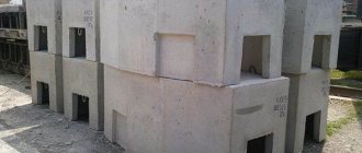
Reinforced concrete prefabricated wells are special elements of buried structures that are used for the construction of various types of communications: sewer, water supply, gas networks and inspection wells. Depending on the area of operation, reinforced concrete rings of various diameters are used for the construction of prefabricated wells.
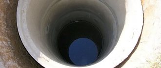
Reinforced concrete wells are a vertical hollow structure consisting of reinforced wall rings, a bottom and a cover on which a hatch is installed. As a rule, wells are almost or completely immersed in the ground and are located above or below the groundwater level in non-aggressive and slightly aggressive environments.
According to their purpose, reinforced concrete wells are divided into several types:
- Tap water. They are elements of the water supply network, heat and water supply and are intended for installing valves (so-called shut-off valves) to regulate the flow of various liquids, fire hydrants, measuring equipment, etc.;
- Sewage (drainage, treatment). Designed to create sewer systems at bends, in places where pipes drop, etc. They are used to combat groundwater that destroys the foundation;
- Gas pipelines. Serve as elements of main gas pipelines.
Based on functionality, wells are divided into several types:
- Observation rooms - used to monitor the operation of the entire system;
- Drop pipes are necessary in places where there are strong differences in pipes, when the network is turned or when the network level changes due to the characteristics of the landscape. They are used when combining pipelines of various depths into one network;
- Rotary. These wells are used in places where pipes turn to avoid blockages. Also often used as viewing rooms;
- Filtration (filtration) wells are necessary for wastewater treatment. Installed above the groundwater level;
- Cumulative. They are used to accumulate wastewater and are usually installed at the lowest point of the site to ensure the optimal angle of inclination of the sewer pipeline.
Advantages of using reinforced concrete as a material for the production of wells:
- Durability of products. Reinforced concrete allows wells to withstand the load that occurs due to soil pressure, and its dense structure is not subject to erosion by groundwater;
- Concrete wells are suitable for most soils;
- The smooth surface of concrete wells does not allow debris to cling to the walls and form blockages. In addition, concrete is easily cleaned, and cleaning does not require special equipment or qualified specialists;
- Unlimited service life. Concrete products are famous for their durability even when used in aggressive environments and places where there is a fairly high level of humidity;
- Simplicity and ease of installation and repair. The elements of a prefabricated well are easily mounted on top of each other. Thanks to this, repairs do not require a complete replacement of the structure - it is enough to just replace or repair the worn element;
- Concrete is inert - it does not have any effect on water quality.
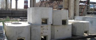
Assembled reinforced concrete wells consist of several elements: wall rings, bottoms, covers and hatches. Road construction involves the use in some cases of wells equipped with floor slabs. The presence of certain elements in the structure depends on the purpose of the prefabricated well. Technically, these elements are divided:
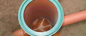
- Concrete rings. They are through thin-walled hollow cylindrical elements that serve directly for forming and laying the well;
- Well covers or, as they are also called, floor slabs. These slabs not only provide protection to the water from contamination, but also prevent the danger of a person falling inside the well. They have a special hole in their design for installing a hatch;
- Bottom plates (bottom). Monolithic reinforced concrete slabs that serve as the bottom and perform the function of waterproofing wells;
- Support rings. These are additional prefabricated elements that are intended for structures of non-standard height for road construction. They are identical in size to standard rings, but have a significantly smaller height;
- Support plates. They have a rectangular shape with a round or rectangular outlet in the middle, which is subsequently closed by a round iron hatch or a rectangular wastewater grate. The rectangularity of the base plate allows you to protect the well itself from destruction. Thanks to this shape, the load is directed evenly over the entire perimeter of the slab, and the walls of the well receive minimal load, which helps maintain the long-term functionality of the structure itself;
- Rings with caps. They are located at the top of the structure and ensure the safe operation of wells. The hole in the lid on which the cast-iron hatch is installed is necessary to provide free access to the inside of the well;
- Sewer wells are standardized cylindrical concrete structures that are designed to create underground sewerage, gas and water supply systems. Inside the sewer well there is a metal mesh 0.6 - 1 mm thick;
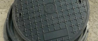
- The hatches are cast iron. They close the wells and prevent large foreign objects from entering the system, and also protect against accidents.
When choosing reinforced concrete wells, it is necessary to take into account the characteristics of the structure being built. For example, concrete rings for wells located on highways are always equipped with floor slabs and hatches, and if it is necessary to ensure watertightness of the structure, concrete rings with a bottom are used.
Prefabricated reinforced concrete wells are manufactured in accordance with the requirements of GOST 8020-90 and series 3.900.1-14. “Reinforced concrete products for round wells for water supply and sewerage”, issue 1 “Instructions for use and working drawings” made of heavy concrete with a compressive strength class of B15. The base plates of the wells are made of heavy B20 concrete. The frost resistance grade of concrete for the working chambers of wells is no less than F75, for other products - no less than F100. The waterproof grade must be at least W6.
Reinforcement of the working chambers of reinforced concrete wells is carried out with volumetric reinforcing cages made on special machines, similar to the type of frames used for reinforcing round reinforced concrete pipes. Road construction also allows for the production of frames by bending conventional reinforcement mesh. Reinforcement of the bottom of wells is done with meshes cut from three-dimensional frames at the holes, with the exception of water and gas wells, the bottom of which is reinforced with special reinforcing meshes. For the reinforcement of structures, types and classes of reinforcing steel are used: thermomechanically strengthened rod of classes At-IIIC and At-IVC according to GOST 10884; hot-rolled rod of classes A-I, A-II and A-III according to GOST 5781; reinforcing wire of class BP-I according to GOST 6727.
Prefabricated reinforced concrete wells and elements are marked with an alphanumeric designation, where:
- CL - working chamber of a sewer well;
- BC - working chamber of the drainage well;
- KFK - working chamber of a domestic sewage well;
- KDK, DK - working chamber of the well of intra-block networks;
- KLK - working chamber of a storm sewer well;
- KLV, VD - working chamber of the storm sewer water intake well;
- KVG - working chamber of a well for water and gas networks;
- KS - wall ring of the working chamber or well neck;
- KO - support ring;
- PO - base plate;
- PD - road slab;
- PN - bottom plate;
- PP - floor slab;
- PC - wall ring with covers;
The numbers after the letters indicate the diameter in decimeters of the working chamber, neck or hatch of the reinforced concrete well with which the element mates. The numbers after the dot in the mark of the wall rings indicate the height of the ring in decimeters. Lowercase letters after the numbers in the type of wall rings indicate the design of the rings with additional design features: a - with two holes for passing pipelines, b - with four. The numbers after the hyphen in the type of floor slabs indicate the type of load-bearing capacity of the slab.
Labeling of products in accordance with the album of unified products RK 2201-82 using an alphanumeric system, where:
- BC - working chambers of drainage wells,
- VD - working chambers of water intake (rainwater) wells,
- VG - working chambers of wells installed on water and gas networks,
- PC - a round slab for covering wells with a hole at the edge of the slab,
- PVG - a round slab for covering wells with a hole at the center of the slab,
- K - well neck rings.
The numbers at the end of the stamps show the internal diameter of the working chambers of the wells and necks in decimeters.
You can order elements of reinforced concrete wells, as well as consult with our specialists and select the required reinforced concrete structures. In our sales department you can find out in advance to clarify the price of wells and calculate the total cost of the order. You can buy wells and consult on general issues of purchase and delivery by calling the BLOK Group company: St. Petersburg , Moscow , Krasnodar: (861) 279-36-00 . Company operating hours: Mon-Fri from 9-00 to 18-00. The company GC BLOK delivers reinforced concrete wells throughout Russia directly to the customer’s site or to the construction site, if the infrastructure allows.
Regulations
The table of sewer wells is compiled on the basis of current standards and rules (SNiP, SP). These are basic documents that list all the requirements for the design of containers, their sizes and other parameters. Any inconsistencies discovered during the defense are regarded as grounds for project rejection.
However, if you use only basic regulatory documents, the risk of making mistakes increases. For each tank you will have to select parameters separately, which will significantly slow down the preparation of the project. The structure of SNiP or SP is designed to list rules, requirements and standards. It is inconvenient for carrying out design work, so a special database has been created to help compilers - the Standard Project (TP). Currently, a more modern edition is used - TPR (Typical Design Solutions), which is a revised version of the database.
Sewer wells, Standard Project is a set of tables for different groups of containers. They are united by purpose, size, and features. The designer’s job is to select the desired option based on the values given in the columns.
Table items
In the table, you can separately consider each sewer well, the design of which is no longer needed separately. Each column indicates certain parameters of the structure. The first contains the node number according to the plan, the second determines the soil conditions. They are designated by Roman numerals:
- I - dry soil, not capable of subsidence;
- II - wet soil (in Russia this is the main type);
- III - subsidence soils.
The remaining columns show the size or type of individual nodes. Most of the values are needed for excavation work (diameter and depth of the tank), and are also necessary for calculating the amount of materials.
The depth of the structure is its total height from the bottom of the tray (or the bottom of the pipe) to the manhole cover. According to current standards, the manhole cover is located flush with the asphalt surface, 5-7 cm above the soil if the well is located on a lawn, or 50 cm above the soil in a forested area.
The height of the working part and neck is taken according to the pipe laying conditions. They depend on the depth of soil freezing and on the profile of the drainage network, distance from the starting point, slope, etc.
The depth of the tray is selected in accordance with TP “sewage wells” 902-09-22.84. It is usually taken to be 100 mm larger than the diameter of the largest pipe entering the container.
The brand of the well is also determined according to TP 902-09-22.84. To do this, the type of container, its size and other parameters are taken into account. Based on the tables given in the TP, a suitable option is selected, for which the types of standard structures are indicated in a separate column. The type of hatch (light, small, etc.) and the type of stepladder for lowering or exiting workers are also noted here.
Also read: Do-it-yourself drainage from sewer pipes - drainage system, features, review
Volumes of tank elements
The volume of the well is determined according to the TP tables. For public sewerage networks, this parameter is not important, since it is not taken into account anywhere. Only other values are considered - height, diameter, etc. However, sometimes volume is important. For example, instead of performing complex calculations, you can accept wet sewer wells using TP. These are reservoirs where temporary storage of wastewater is carried out. Wet wells include:
- storm water intake wells;
- storage tanks in private homes;
- drainage tanks, etc.
For such structures, volume plays an important role, since the amount of waste is expressed in appropriate units.
The height of the pipe drop is needed only for drop wells, since in other structures a “shelyga to shelyga” connection is used.
The volume of concrete per tray is determined by the TP, but sometimes you have to count it manually. This is necessary if non-standard well elements are used. Knowing the amount of material, you can immediately calculate the total volumes of building materials for building the system. There is no point in calculating each well separately; the project allows you to immediately determine the full volume of concrete or other materials for all structures. This significantly speeds up the process of preparing working documentation and also allows you to avoid errors or inconsistencies.
Calculation of the volume of a sewer well
The construction of wells begins with choosing a location and calculating the volume of the well. And, perhaps, you first need to calculate the required volume, and then choose a place for the waste volume.
The volume of the sewer well directly depends on the number of people living in the house and the available bathrooms.
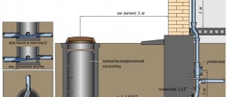
The volume of the well intended for sewerage directly depends on the need for water consumption. Average waste water rates per person are 150-170 liters of water per day without a bath and 230-250 liters of water per day with a bath. For an average family (two adults and two children), water consumption per day can be from 600 to 1000 liters (one cubic meter). It is generally accepted that a resorption well with a bottom area of 1 sq. m is capable of receiving and absorbing up to one cubic meter of water per day (provided that the soil is non-clayey). To ensure some reserve, the working volume of the pit is calculated as three times the daily norm, that is, for our average family of four people it is necessary to build a pit with a volume of three cubes. It must be understood that the pipe through which sewage will flow into the pit must be located at a depth of about 70 cm and the working volume of the sewer well is located below the drain pipe. It is also possible to drain the existing drainage system into the sewer pit. Its depth also does not exceed 70 cm.
Now, knowing the required volume of the sewer, we can estimate its size. The depth of the well is usually made from 2.5 to 3 meters. Subtract 70 cm lying above the drain pipe, we get a maximum working depth of 2.3 meters.
Let us remember from the school geometry course that volume is the area of the bottom multiplied by the height.
The most common are round wells, as they are more convenient to install, repair and operate.
The bottom of the well can be round (barrel wells) or in the shape of a quadrangle (square or rectangle). Of course, it is possible to make a sewer pit oval or pyramidal, but this is due to special interest in this kind of construction. We will look at the simplest and most common forms.
The area of a circle is calculated using the formula S = πR2. We find that the required volume of a well of 3 cubes is equal to the product of the height (2.3 m) by the number π (3.14) and by the square of the radius (R2).
3 m3 = 2.3 m *3.14* R2
Having carried out calculations, we find the value of R, it turns out to be equal to 0.65 meters or 65 cm, which means that the diameter of the pit should be 1.3 meters with a depth of 3 meters.
If the well is supposed to be dug not round, but square or rectangular, then remember that the area of the rectangle is the length multiplied by the width. The volume of a well is the depth multiplied by the bottom area. That is, 3 m3 = 2.3 m * bottom area.
Bottom area = 1.3 square meters. This means that either the bottom is square with a square side of 1 m 15 cm, or the bottom is rectangular with sides 1.5 m and 0.9 m. With a well depth of 3 m.
When digging a hole for a well, you must not forget that at the bottom there will be a 30-40 cm cushion of sand and crushed stone.
The sewer is dug taking into account the additional width, length and depth, which will be occupied by reinforcing walls that protect the earth from crumbling. The walls inside the well are erected as formwork and can be made of brick, concrete or reinforced concrete rings. At the bottom of the pit it will be necessary to pour a layer of sand and a layer of crushed stone with a total height of 30-40 cm to filter the absorbed wastewater. If we take into account the size of the brick in the masonry of 12 cm, it turns out that you need to dig a hole 25 cm wider (12 cm of brick width on each side) and 40 cm deeper (layer of sand, layer of crushed stone).
Calculations of the volume of a sewer well and a hole for it allow us to be approximate; here it is possible to round up the values of the values. According to the principle “it is better to have a well with a small supply than to have insufficient volume.”
In addition, you need to know that reinforced concrete rings are produced in standard sizes (0.7, 1, 1.5 and 2 meters - ring diameter). Therefore, having carried out calculations and found out what diameter of the well you need, we compare it with the ready-made standard dimensions of the concrete ring. Having received a calculated diameter of 1.3 meters, we choose rings with a diameter of 1.5 meters, since the industry does not produce rings with a diameter of 1.3 meters.