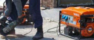
The main reasons for the failure of inverters and their manifestations
The main reasons for the failure of welding inverters are violations of the rules of their operation. You can learn about the operating modes and maintenance features of a particular device from its passport; in general, approximately the same list of activities is given:
- daily external inspection of the main unit and cables;
- periodic internal cleaning of the device with compressed air;
- routine inspection, cleaning, pulling and repair of connections of internal power contacts;
- measuring insulation resistance and checking protective grounding circuits.
The main factors that cause inverter malfunction are:
- Sudden changes in input voltage. Its fall leads to instability and termination of the inverter's operation, while a significant excess can cause failure of the elements of the input rectifier.
- Mineral dust. Covers the surfaces of the internal parts of the device and clogs the ribbed surfaces of radiators for cooling diodes and transistors. This leads to a violation of the thermal regime and can cause failure of individual elements.
- Metal dust and fine shavings. It gets inside the inverter through the input fan if work is being done next to it with grinders, grinders, etc. It can cause an internal short circuit.
- Water and high humidity. Causes oxidation of wires and contacts and can lead to a short circuit.
- External mechanical damage. Sometimes they cause failure of controls and internal structural elements on which electronic components are attached.
The following describes the main malfunctions in the operation of inverters and their causes.
Arc instability, metal spatter
If there are significant fluctuations in the input voltage or incorrect operation of the inverter control system, abrupt changes in the welding current occur, which leads to arc instability. In this case, first of all it is necessary to check the network voltage. If it is normal, but the oscillations continue, internal diagnostics of the inverter should be performed.
Spattering of metal during welding is usually a consequence of incorrect selection of welding current. The reason for this may be either a human factor or a malfunction of the current regulator or control system.
Inverter does not turn on
This phenomenon may have several reasons:
- poor contact of the ground cable clamp;
- input voltage too low;
- the input circuit breaker has turned off (the reason for this may be an internal short circuit);
- The thermal protection has tripped.
In the latter case, you need to wait until the device cools down and try to turn it on again. If the protection trips repeatedly, the inverter requires maintenance or repair.
Inverter overheating
The main reason for overheating of the inverter is a violation of thermal conditions due to a large amount of dust in the internal space of the device. Dust acts as thermal insulation, covering the surfaces of components cooled by the air flow, and does not allow fans to operate normally. If there is constant overheating, before talking about diagnostics and repairs, it is necessary to carefully and very carefully clean all internal modules with compressed air. Another reason for overheating of the inverter is non-compliance with the recommended value of the PV parameter (on duration).
Increased power consumption
Increased power consumption at idle at the standard value of the input voltage of the network is usually associated with a short circuit between the turns of one of the windings of the high-frequency transformer. Externally, such a malfunction looks like burning of the insulation around its live parts and is most often accompanied by a drop in the no-load voltage (sometimes by two to three times). It is not difficult to remove, disassemble and inspect the transformer yourself, but it is better to entrust its repair to someone who is well versed in this.
Electrode sticking to metal
If the electrode sticks during the welding process, most likely this is caused by incorrect selection of technological parameters and poor preparation of the surfaces to be welded. In addition, to prevent this phenomenon, all modern inverters are equipped with an automatic Anti-Stick function. When the value of the welding current corresponds to the diameter of the electrode and the thickness of the metal being welded, and the welding zone is cut and cleaned properly, the cause of sticking (sticking) may be a periodic decrease in voltage both from the electrical network and directly in the welding circuit.
In the first case, it is necessary to stabilize the mains power supply or use an inverter with the ability to operate at reduced voltage. On the welding chain side, the contacts must be periodically cleaned and their reliability checked. In addition, a voltage drop can be caused by the use of cables whose length and cross-section do not meet regulatory requirements.
Inability to adjust current
First of all, we can talk about a malfunction of the indicator that displays the current value. Also, one of the most common reasons is a broken wire, breakdown or internal wear of the potentiometer, which sets the value of the welding current. If all this is in order, then the problem may be a malfunction of the inverter control system. Only an experienced specialist can understand it and perform such repairs.
Spontaneous shutdown
The reasons for sudden shutdowns of the welding inverter can be sudden surges in the supply voltage, a malfunction of the input circuit breaker, and the operation of temperature protection. In the first case, it is necessary to somehow stabilize the input voltage or use a device designed to operate in this range. If the temperature protection is frequently triggered, it is necessary to clean the internal part from dust and check compliance with the manufacturer's recommendations for the duration of continuous operation. You can check the serviceability of the input machine without complex repairs by temporarily connecting a known-good device instead.
Procedure for repairing devices
Failure and failure of the welding inverter can occur either due to a serious breakdown or due to a minor malfunction. Before contacting a service center or a familiar technician, it makes sense to consider the option of doing the repair yourself, especially if the owner has specialized education or amateur radio skills. The inverter should be disassembled, cleaned and carefully inspected from the inside, as the problem may be excess dust or some loose wiring, and no major repairs are really needed.
If you decide to carry out repairs yourself, then the following minimum set of tools is required:
- Digital multimeter. The most common one, the “diode test” function is optional, since all semiconductors can be checked in resistance measurement mode.
- Soldering iron with accessories. A soldering station is better, but you can get by with a soldering iron with a thin tip of 40–60 W.
- Screwdrivers, pliers, wire cutters, tweezers.
It is often written that to check the condition of an inverter device you definitely need an oscilloscope. But this is a different level of knowledge and skills with different recommendations for troubleshooting. Our actions for diagnosing and repairing the inverter will be limited to a visual inspection, continuity testing, basic measurements of the condition of the main elements of the inverter’s electronic circuit and their replacement in the event of a malfunction. If all this does not bring results, then you need to contact specialized specialists.
Read also: Tool for detecting hidden wiring
The procedure for the first stage is as follows:
- Remove the housing and clean the inverter from dust with compressed air. Select the pressure so as not to damage printed circuit boards and electronic components.
- Check the condition of the fan blades and the ease of their rotation. If problems are found, replace them with new ones. Check that all wires and connectors are securely connected.
- Check the connection and condition of the welding current adjustment potentiometer. In case of malfunction, repair or replacement.
- Inspect the windings of transformers and chokes for burning. If there are defects, dismantle and send for inspection or immediately rewind.
- Check the elements of the power circuit (capacitors, charging resistor, diodes, transistors) for damage to the external housing. If defects are found, replace with the same or analogues.
- Carry out an external inspection of the control system printed circuit board. If there are damaged elements, then carefully remove them and replace them with new ones (if you have never soldered printed circuit boards, then it is better not to do this, but immediately contact a specialist).
If, after an external inspection and elimination of detected problems, the inverter does not turn on or operates incorrectly, it is necessary to diagnose individual circuits and power elements (see below).
Inverter diagnostics
Testing of semiconductor electronic components is carried out by measuring the resistance at their terminals by changing the polarity of the multimeter. In one case it should be close to zero, in the other - infinitely large.
Before you begin diagnosing the inverter, you must connect a 100÷150 W incandescent light bulb in series with it, which will stabilize the current and serve as protection against short circuits. In addition, by the glow of the light bulb one can judge the working condition of capacitors and power transistors.
We diagnose the inverter in the following sequence:
- Checking the power diodes of the output rectifier. We measure the resistance at the output terminals of the inverter with a multimeter. One way should be zero, the other should be infinity. If this is not the case, then we proceed to repair: we identify the faulty diode and replace it.
- Checking the power transistors of the RF converter. First you need to determine the type of arrangement of the transistor pins. We measure for “breakdown” by changing the polarity between the gate and the other two terminals. If it is zero in both directions, then the transistor is faulty and must be replaced.
- Checking the diodes of the LF rectifier. Here the diodes are connected in a bridge circuit, so first you need to determine the four contact points. At zero in both directions the diode must be replaced.
- If all power semiconductors of the devices are in good condition, you can connect the inverter to the network. In this case, the light bulb connected in series with it will first flash for a few seconds, and then, as the LF rectifier capacitors charge, it will begin to dim noticeably. If at least one of the transistors of the RF converter is broken, the light bulb will burn at full intensity.
- The inverter can then be turned on and off several times using the key on the front panel. After this, it is necessary to measure the open circuit voltage in several positions of the current regulator (it will be slightly less than the nominal one).
Before repairing the welding inverter, it must be disconnected from the power supply. The light bulb circuit can only be used at idle. It is best to check the device under load with a ballast rheostat.
Replacing transistors
When repairing a welding inverter, you may have to replace transistors, zener diodes, resistors and other electronic parts. To do this, you need to have some skills in soldering such products. When replacing transistors (IGBT and MOSFET), you must remember that they can fail under the influence of static electricity. It is recommended to work with them on antistatic surfaces and wearing wristbands to protect against static. In fact, few people fully follow these instructions, but it is still necessary to know about them.
In order to replace the power transistor, you need to unscrew the screw that holds it to the radiator, separate its body from the surface, and then carefully unsolder it. Installation of the new transistor is carried out in the reverse order; before pressing it with a screw to the radiator, you need to apply a thin layer of heat-dissipating paste to the contact point.
Rectifier repair
The inverter contains three rectifiers: a half-wave output and two bridge rectifiers: an input and an internal power supply (“standby”). The first one contains two diodes and is checked with a multimeter through the input terminals of the inverter, and bridge diodes - at four points (on the connectors or on the board). When repairing rectifiers, diodes, capacitors and ballast resistors are most often replaced. There are no special precautions when soldering these elements, although when replacing parts of the internal power supply you need to be extremely careful: they are installed on the printed circuit board. The diodes of the input and output rectifiers are mounted on radiators. When installing a new element, be sure to use heat-dissipating paste before fixing it with a clamping screw.
Capacitor diagnostics
The main reasons for the failure of electrolytic capacitors are mechanical damage, significant excesses of the rated voltage, failure of internal contacts and aging. In the first two cases, malfunctions can be detected visually, while the ends of most models of electrolytic capacitors have special notches that rise or open when the electrolyte “explodes” (see photo below).
Hidden faults are quite easily detected by a device with a capacitance measurement function or a conventional multimeter. In the latter case, the pre-discharged capacitor initially shows a small resistance, which increases to infinity as it is charged from the multimeter source. When measuring at the contacts of a faulty capacitor, the device shows either an open circuit or some kind of constant resistance.
Control board repair
If simple diagnostics with a multimeter and subsequent repairs do not give the desired result, then the source of the problem is most likely the control board. Without an oscilloscope, here you can only check the voltage values at the contact points of the board indicated on the diagram, as well as measure the supply voltages and ring the semiconductor devices (which, most likely, will have to be soldered). In addition, to repair the control board, you need good knowledge of radio electronics and the ability to understand the circuits of electronic devices. For those who do not have such qualifications, there is only one option left - to a service center or to a specialist with a good reputation.
We think this article lists all the possible steps to diagnose inverter faults using a multimeter. If we missed any important points, write about it in the comments and tell us about your experience in repairing an inverter device.
Such a problem, the nikkey mma160 inverter burned out. There were problems with the power supply, several resistors were grounded, an irfpe40 field switch, capacitors for the power supply. Crank (voltage stabilizer - 12v) - supplies power to the control board. After the entire replacement, the welder started working, but it hardly welds, the current regulator does not change anything. It only welds at minimum currents, what do you recommend?
First check if the add-on is stable. the feeder holds 26 volts and do they sags under load? Do the same with the 300 volt input. It won’t help - I think they gave you an analog diagram, look at the feedback.
Then I saw your old post. If Krenka was stitched, then see the council. Get the diagram in hand and go ahead.
I have two mikruhi on the control board, maybe one of them crashed. Since 24 volts went there, then in principle there is nothing else to burn.
Alexander_16 wrote: I have two mikruhi on the control board
batko, There are most likely CA3140 and KA3525. Well, just a little more binding.
Read also: How many revolutions does an angle grinder have per minute?
Yes, these are the ones that are there, sa3140, ka3525, but how can you check them?
look stub +5 volts, check the voltage + 5v on the current regulator. Your 3140 and 3525 are working properly, otherwise you would have noticed it immediately, as would your neighbors.
Another capercaillie. Well, no one immediately told him that 24V for these MCs is not the voltage at which they burn. And in his first post tehsvar already talked about the reason for the failure, there you need to check the OS according to the current. In general, without basic knowledge in the field of power electronics, it is better to immediately take such things to the service center, and where there is none, to the local Kulibin, this is not a radio receiver.
No big deal, the 5V bank is dead
Is there such a thing there? In my opinion, +5V for the stabilization circuit comes from the VREF pin of the PWM controller. And the guy is smart, he quickly went through his topic on sites with a power theme (I saw him here ">), apparently that’s why he abandoned the topic here, because it turned out to be tastier there.
Dear power experts, I went through a lot of things on my welder regarding current adjustment, but in the end there was a slightly noticeable break in the wire to the current adjustment trimmer, so it turns out that I was fooling myself and you in vain, but still thanks to everyone who joined in my trouble when it didn’t work at all, they still helped me get it started, now it cooks even well, and at the same time I’ve already gained more experience. In general, thank you all very much.
When buying an inverter welding machine for work in a garage or in a country house, the first thought is - wow, now I can cook everything! You do not need a welding diploma; the device is designed for users without special education. Handling welding has become easier and more comfortable. The main thing is to understand the principle of operation and first aid in case of difficulties and breakdowns.
Recommendations for DIY repairs
When repairing inverter-type welding machines, you should adhere to a certain algorithm:
- If a malfunction occurs, you must immediately disconnect the electrical device from the network, allow it to cool, and only then open the metal casing.
- Diagnostics must begin with a visual inspection of the electrical components of the inverter. There are often cases when repairing an inverter welding machine involves simply replacing damaged parts or soldering conductive contacts. Visually enlarged capacitors or cracked transistors should be replaced first.
- If a visual inspection fails to determine the cause of the malfunction of the welding machine, you must proceed to checking the parameters of the parts using a multimeter, voltmeter and oscilloscope. The most common failures of power units are associated with malfunction of transistors.
- After replacing the electrical elements, it is worth moving on to checking the printed conductors located on the inverter board. If you find torn or damaged tracks on the printed circuit board of a welding tool, you must immediately eliminate the defect by soldering jumpers or restoring the tracks using copper wire of the required cross-section.
- After completing work with the tracks, it makes sense to move on to servicing the connectors. If the inverter device stopped working gradually, then there may be poor contact in the connecting connectors. In this case, it is enough to measure all contacts with a multimeter and clean the connectors with an ordinary household eraser.
- Despite the fact that malfunctions of a welding inverter are rarely associated with diode bridges, it would be a good idea to check their performance. It is better to diagnose this electrical element in a soldered state. If all the legs of the bridge are short-circuited, then you should search for the faulty diode and replace it.
- The last step in inverter repair is checking the board and control panels. Diagnostics of all components of the board should be carried out using a high-resolution oscilloscope.
When performing independent repair work, you should not forget about the safety rules:
- Do not use electrical appliances without a protective top casing;
- all diagnostic and repair work should be carried out on completely de-energized equipment;
- It is safest to remove accumulated dust and dirt using an air flow generated by a compressor or a compressed gas cylinder;
- Cleaning of printed circuit boards must be done using neutral solvents applied to a special brush;
- Long-term storage of electrical appliances should be done in dry rooms and completely switched off.
Most inverter electrical appliances are supplied complete with accompanying documentation. In these papers you can find a description of the most common faults and repair methods. Therefore, if malfunctions occur, you should carefully study the documentation and only then begin repair work.
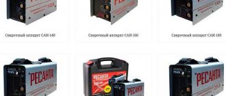
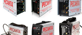
Inverter machines - a new generation of manual welding
Since the beginning of 2000, inverter welding machines have become cheaper and more accessible. To carry out welding work at home, it is enough to have this small and easy-to-use device and good electrodes.
Advantages of inverters
Inverter machines are lightweight, compact in size, and their scope of use and welding quality are higher than those of heavy and bulky welding transformers. They carry out their task in full: they weld cars, gates, pipe structures (for example, greenhouses or gazebos). Working with them is mobile - throwing an extendable belt over your shoulder, welding is carried out in any hard-to-reach places.
When vertical, horizontal or overhead welding, the current is reduced by 10–20%, and when welding at an angle, it is increased by the same amount compared to the normal position.
There are also no problems with the connection; the welding machine operates from a regular electrical network. It's great that it won't stop when the mains voltage drops. If the deviation is within +/- 15%, the device will continue to operate normally. The current value can be adjusted by selecting the power depending on the type and thickness of the metal. All this makes inverters ideal for both beginners and professionals.
Video: testing a homemade inverter device
How welding inverters work
The inverter unit connects parts with direct current using electric arc welding with a coated electrode. The big plus is that at the very beginning of the process there are no power surges in the network to which the device is connected. The storage capacitor ensures uninterrupted electrical circuit and soft ignition of the arc with its further automatic maintenance. When connected to an electrical outlet, the alternating mains voltage with a frequency of 50 Hz is converted first into direct voltage and then into high-frequency modulated voltage. Then, using a high-frequency transformer, the current increases, the voltage decreases, and the output current is rectified. The device provides adjustment of the welding current value and protection against overheating.
The inverter device first rectifies and modulates the input current, and then increases its strength by reducing the voltage until the arc appears
The basic operating mode of inverter welding machines is MMA. This is manual arc welding with piece coating electrodes. For welding steel and cast iron products using direct or alternating current, a diameter of 1.6–5.0 mm is used.
The devices differ in power and operating cycle duration .
The second indicator is the period during which it is allowed to cook at the maximum permissible power in order to prevent the device from overheating. It is designated by the letters PV (on period) and is determined as a percentage relative to a time unit of 10 minutes. For example, if the device indicates a PV of 60%, this means that it can be cooked for 6 minutes and then turned off for 4 minutes. Sometimes the welding cycle is set to 5 minutes. Then a PT value of 60% means a work period of 3 and a rest period of 2 minutes. PV and duty cycle indicators are indicated in the instructions for each device.
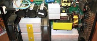
Welding machine design
In order not to look for a repair specialist at the first difficulties in the operation of the device, it is advisable to have at least a basic understanding of its design.
DIY inverter assembly diagram
Craftsmen with knowledge of electrical engineering assemble the welding machine themselves. Not only for the sake of economy, but also at the behest of the creative soul. The Internet contains schematic diagrams of inverters, drawings and instructions from those who made the inverter themselves. The main thing is to obtain stability of the welding arc. Most often, an “oblique bridge” circuit (“Barmaley circuit”) is used using two key transistors: bipolar or field-effect. They are placed on a radiator to remove heat; they open and close synchronously.
In the “Barmaley circuit” the main control elements are two transistors, which open and close synchronously
The electrical solution of the circuit eliminates high-voltage emissions and allows the use of relatively low-level switches. The scheme is used because of its simplicity, reliability and not very expensive consumables.
Video: review of the Barmaley scheme
DIY inverter assembly
The apparatus is assembled from the following blocks:
- power supply for stabilizing input signals. A metal partition is placed between it and other elements and blocks. The multi-winding inductor is controlled by transistors and a capacitor with stored energy. The throttle control system uses diodes;
- power unit, with the participation of which a full cycle of current conversion takes place. Assembled from a primary rectifier, an inverter transistor converter, a step-down high-frequency transformer and an output rectifier;
- Control block. It is based on a master oscillator with a special microcircuit or a pulse-width modulator. They install a resonant choke and 6–10 resonant capacitors;
- protective block. More often they are assembled on a power unit, installing thermal switches for thermal protection of its elements. To avoid overloads, install a board based on the 561LA7 chip. Snubbers with resistors and capacitors K78–2 protect the converter and rectifiers.
Video: assembling a welding inverter
Reasons for failure of inverters
The design of inverter welding machines is more complex than transformer welding machines and, unfortunately, less reliable. This often leads to failure of various components for the following reasons:
- low protection from dust. When it accumulates inside, a thermal protection signal is triggered and the device turns off. Requires disassembly at least twice a year to clean the internal parts with a jet of compressed air or a soft brush;
- moisture getting inside, causing a short circuit that is dangerous for the unit;
- low quality cooling system in cheap devices. Because of this, the plastic parts of the structure melt and the emergency shutdown does not work. In models with tunnel ventilation, the radiator is located along the body, and the main components are located inside it. Such devices are much more expensive;
- voltage surges, especially drops to 190 V or more;
- overload when cutting thick metal and work for which a particular device is not designed. Then the IGBT power module fails;
- poor-quality fastening in the contacts of the pads, which provokes overheating of these places and sparking;
- sensitivity to shocks and falls due to the presence of plastic parts;
- low quality of spare parts used for repairs;
- violation of the permissible temperature regime. Electronic microprocessors melt and destroy when overheated. It is recommended to adhere to the range from -10 to +40 o C.
Read also: Size control tool
Frequent breakdowns of welding inverters
Malfunctions can be either mechanical or related to electronic failure. A welding machine is a complex device, problems can arise anywhere:
- breakage of racks, especially in cheap models. Light and fragile devices cannot withstand shock;
- inoperative fan - in case of critical overload, overvoltage protection is triggered. The same happens if the device operates in the on-off mode for a long time;
- a defect in the connection between the switch and the bottom panel prevents the fan from working and leaves the device without voltage;
- an incorrect connection inside the device turns off the fault indicator, but there is no voltage;
- poor contact of the ground clamp in the housing socket or with the part prevents the arc from being ignited and maintained. The terminal block to which the welding cable is connected is the weak point of any welding machine;
Poor contact at the point where the cables are connected to the welding machine or to the workpieces does not allow obtaining a stable arc
A short circuit or breakdown in any important component of the electrical circuit makes it impossible to operate the welding machine:
- a malfunction of the control board does not provide a stable welding current and does not allow a normal arc to be obtained;
- damage to the transistor on the upper printed circuit board leads to the device shutting down;
- Failure of the overheating protection system is determined by the smell of burnt insulation and smoke coming from inside the housing.
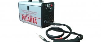
Methods for repairing inverter welding machines
When starting to repair a faulty unit, it is worth considering some points.
What can be fixed without opening it?
Poor performance of the device does not always mean internal failure. Wet or poor-quality electrodes are often the culprit. If drying or replacement does not produce a beautiful seam, consider other possible reasons:
- poor ignition, sticking of electrodes to the metal often occurs due to loss of power in the work cables or low welding current. Correct selection of cable cross-section and increasing the current strength can solve the problem. Do not use power extension cords with a wire cross-section of less than 2.5 mm 2 or too long. The optimal length is up to 15 m, the maximum is 40 m, otherwise the device will not work due to loss of current. Welding cable is recommended up to 5 m long;
To connect the welding machine, you must use an extension cord with a wire with a cross-section of at least 2.5 square meters. mm and length no more than 40 m
Weld defects occur due to insufficient cleaning of the treated surfaces, incorrect polarity or too far distance of the electrode from the welding site
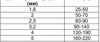
It is important to choose the correct electrode size for proper operation of the welding machine.
Table: correspondence between the diameter of the electrodes and the thickness of the metal
| Electrode diameter, mm | >12 |
Internal organization
To be able to repair a welding machine yourself, you first need to understand its internal structure. The front panel contains sockets for working cables, a current control knob and a power indicator. If the design provides additional functions, operating indicators are located here.
On the front panel of the welding machine there are sockets for connecting cables, a current control knob and an operating mode indicator
The check begins with an external inspection of the device. First of all, check for mechanical damage. If there are black spots on the case, most likely there is a short circuit. The tester checks fuses, replaces them if necessary, inspects the insulation of welding cables and connections in sockets. If necessary, tighten the bolts and clean the contacts.
After unscrewing the screws and removing the casing, the interior of the device is revealed, where the following components are located:
- board with power transistors;
- control board;
- rectifier diode board;
- mains voltage rectification board;
- fan;
- controls - knob and switches.
Tools for work
The following tools will be required for repairs:.
- Multi-mode multimeter:
- chain ringing;
- diode ringing;
- voltage measurement;
- resistance check.
- Oscilloscope. It is used to test diodes, zener diodes, transistors, capacitors and other elements of the electrical circuit. Without an oscilloscope, repairing a welding unit is much more difficult.
The use of an oscilloscope provides higher accuracy in determining the causes of welding machine malfunctions
Low current in the welding inverter
. What you can do is take it to the office where they fix it, and not break it, then the repair will be more expensive.
At the very least, you can ask HERE or HERE, but most likely the answer will be similar.
JLCPCB, only $2 per PCB prototype! Any colour!
Register and receive two coupons for $5 each: https://jlcpcb.com/cwc
Well thanks for the help. Made friends. But I don’t sit on other forums. I am a fan of Kote radio.
I calculated the Rt and Ct chain for uc3846n and according to the calculation it came out to 100 kHz. but not like 400 kHz. So I'm off to get some capacitors and a uc3846. and I'll grab tl084 just in case. but I'll be honest. I really can’t believe that it’s the PWM controller that’s to blame. but don’t believe it that’s all. but nevertheless we need to check this version too
PCB Assembly from $30 + FREE Shipping Worldwide + Stencil
_________________ You don’t know which concentration camp they are taking us to? Not. Don't know. I'm not interested in politics.
and Analog Devices invite everyone to participate in a webinar on 04/27/2021 on Analog Devices galvanic isolation solutions. The webinar program includes: iCoupler galvanic isolation technologies, digital isolators, isoPower technology, galvanically isolated interfaces (RS-485, CAN, USB, I2C, LVDS) and more. The webinar will be of interest to developers of industrial automation and medical equipment.
The wide range of Degson screw terminal blocks includes various variations with pin pitches from 2.54 to 15 mm, with the number of tiers from one to three and conductor connection angles of 45°, 90°, 180°. In addition, Degson offers a fairly large selection of screw terminal blocks in custom colors.
it’s all in vain but somehow
channel A and channel B respectively.
It’s strange that the frequencies differ PRIEST is expanding its range
_________________ You don’t know which concentration camp they are taking us to? Not. Don't know. I'm not interested in politics.
so what should I do? They brought it to me for repairs and should I go to the repair shop myself so they could fix it? They'll take the money there. I'll still be in the red
going for repairs is unthinkable. and return the non-working one too. I'll do it myself
_________________ You don’t know which concentration camp they are taking us to? Not. Don't know. I'm not interested in politics.
_________________ Although optics magnify images, looking through an optical sight, all problems become smaller.
Oh well. I want to collect a chameleon sampler. Yes, I can’t get it together. It would be a good helper in this matter. Why do you think I don’t have knowledge? I don’t understand in detail, of course, but I understand the principles. so I start checking based on what I know. Of course I have a multimeter. even three pieces. two digital and one pointer. digital burned. but then he repaired them. work great.
but to the point. I'll try to look for schematics for this welder. If not, I'll try to make it up. but it will be difficult. I'll try to redraw the main control module. but first I'll try to replace the shim. I don’t like the fact that the output transistors are intact but there is no current.
Well, dear cats. I was looking for the reason and it looks like I found it. 16 pin UC3846n (External shutdown signal input) Input of an external shutdown signal. It is connected to op amp tl084 to one of four channels. And I check the op-amp and it turns out that the op-amp, based on the positive signal at the inverting input, does not attract the power supply to the minus. It turns out that the 16th leg of the PWM controller has constant positive power. Perhaps this is the issue after all. How do you think?
_________________ ========= Forum Rules HERE _____ Rules of the BAZAAR section HERE _____ If you are selling, read HERE
I rarely appear. If the question is not of a personal nature, use the “!” button. .
_________________ You don’t know which concentration camp they are taking us to? Not. Don't know. I'm not interested in politics.
Time zone: UTC + 3 hours
Who's on the forum now?
This forum is currently viewed by: Bing [Bot] and 28 guests
Source
DIY welding machine repair
The filling of the welding machine is clear to those who work with radio electronics. If the necessary skills in this area are not available, intervention will only do harm. Without knowing the rules for handling the board and the technology of such delicate work, you can cause damage much greater than the initial one. It is cheaper and safer to entrust the repair to a professional.
If it is difficult to find a specialized workshop, you have to restore the welding inverter yourself. It is important to check one by one what stopped the device from working.
If difficulties arise, first read the operating instructions for the welding machine. It must have a section about possible problems during welding, the causes of malfunctions and recommendations for eliminating them.
After removing the cover of the device, a violation of the soldering of parts, swelling of the capacitors, and broken contacts are often noticeable. In such cases, damaged spare parts are replaced with similar ones. Torn and burnt areas are removed and re-soldered. If it is not possible to quickly determine the cause of the breakdown, each element of the electrical circuit is checked. Diodes, transistors, zener diodes, resistors and other parts are tested.
A detailed check is carried out sequentially: from the parts that most often fail to the most resistant.
- Power diodes. To check their continuity, the tester is switched to diode mode, and the probes are touched to the output terminals. If there is ringing in one direction, but not in the other, the power diodes are in order, the lower module of the device is working.
If the input terminals only ring in one direction, then the power diodes are working properly
Power transistors are checked using a tester in three combinations of probe positions
The button is checked in the “on” mode by ringing its contacts
The diode bridge is tested by touching each of its terminals in turn.
The field-effect transistor in the primary power supply is dialed in the same sequence as the power transistors
If the light bulb connected in series with the device lights up, the power units are working properly
To check the charging resistor, check the serial chain of PTC and NTC
Testing of the key control board is carried out with a tester when the device is turned on in voltage mode up to 20 V
When searching for a break in the reverse connection, the red probe is installed on the second pin of the microcircuit
Before checking the power supply, unplug the device from the outlet!
At the first stage of repairing the power supply, check for the presence of a voltage of 300 V on the inverter board
When doing self-repairs, craftsmen use phosphoric acid. If something needs to be soldered to the diode cases (for example, broken stands), they are first tinned. When repairing a broken post, perpendicularity is taken into account. It is important to install it, clearly aligning the holes. If you solder even with minimal distortion, the post will break again when you subsequently tighten the fastener.
If there is no technical hair dryer, use a 100–150 W soldering iron for desoldering. This will prevent damage to the connectors and tracks. For better results, experts recommend heating the block to 160–170 0 C before soldering, but the plastic parts of the fan should not be heated. When working with a soldering iron or other heating elements, care must be taken not to touch the fusible parts of the device.
Video: repair of a welding machine and analysis of its main faults
An inverter welding machine is confidently prescribed in home workshops. Before purchasing, it is worth spending time learning the basics of welding and electrical engineering. This will help you navigate the characteristics of the device and, if necessary, repair it yourself. It is better to entrust complex cases to specialists.
Malfunctions of inverter devices
Before repairing an inverter welding machine with your own hands, it is advisable to familiarize yourself with the principle of operation, as well as its electronic circuit. Knowing them will allow you to quickly identify the causes of breakdowns and try to eliminate them in a timely manner.
Electrical diagram
The operation of this device is based on the principle of double conversion of the input voltage and obtaining a direct welding current at the output by rectifying the high-frequency signal.
The use of an intermediate high-frequency signal makes it possible to obtain a compact pulse device that has the ability to effectively regulate the output current.
Failures of all welding inverters can be divided into the following types:
- malfunctions associated with errors in choosing the welding mode;
- operational failures caused by failure of the electronic (converter) module or other parts of the device.
The method for identifying inverter malfunctions associated with disturbances in the operation of the circuit involves sequential execution of operations carried out according to the principle “from simple damage to more complex damage.” The nature and cause of breakdowns, as well as repair methods, can be found in more detail in the summary table.
It also provides data on the main welding parameters, ensuring trouble-free (without turning off the inverter) operation of the device.
Features of operation
Maintenance and repair of inverter-type welding machines differs in a number of features related to the complexity of the circuitry of these electronic units. Repairing them will require certain knowledge, as well as the ability to handle measuring instruments such as a digital multimeter, oscilloscope and the like.
In the process of repairing an electronic circuit, a visual inspection of the circuit boards is first carried out in order to identify burnt or “suspicious” elements within individual functional modules.
If during the inspection no violations can be detected, the troubleshooting continues by identifying violations in the operation of the electronic circuit (checking voltage levels and the presence of a signal at its control points).
To do this, you will need an oscilloscope and a multimeter, which you should start working with only if you have complete confidence in your abilities. If you have any doubts about your qualifications, the only right decision is to take (take) the device to a specialized workshop.
Specialists in the repair of complex pulse devices will quickly find and eliminate the malfunction, and at the same time carry out maintenance of this unit.
Self-repair procedure
If you decide to repair the board yourself, we recommend using the following advice from experienced specialists.
If burnt wires and parts are discovered during a visual inspection, you should replace them with new ones, and at the same time reconnect all connectors, which will eliminate the possibility of loss of contact in them.
If such repairs do not lead to the desired result, you will have to begin a block-by-block examination of the electronic signal conversion circuits.
To do this, it is necessary to find sources that provide voltage and current diagrams intended for a more complete understanding of the operation of this unit.
Focusing on these diagrams using an oscilloscope, you can sequentially check all electronic chains and identify a node in which the normal signal conversion pattern is disrupted.
One of the most complex components of an inverter welding machine is the electronic key control board, the serviceability of which can be checked using the same oscilloscope.
If you have doubts about the functionality of this board, you can try replacing it with a working one (from another, working inverter) and try to start the welding machine again.
If the outcome is favorable, all that remains is to send your board for repair or replace it with a purchased new one. The same should be done if there are suspicions about the serviceability of all other modules or blocks of the welding machine.
In conclusion, let us recall that the repair of any welding units (and inverters, in particular) is considered a rather complex procedure that requires certain skills and the ability to handle complex measuring equipment.
If you have the slightest doubt about your professionalism, you should use the help of specialists and give them the opportunity to return the faulty device to work.
Source