PLASMA TECHNOLOGY
PLASMA TECHNOLOGY, technological processes based on the use of low-temperature plasma generated by arc or high-frequency plasmatrons. Used for carrying out dif. metallurgical processes (see Plasma metallurgy) and thermal. processing - welding, cutting, metal surfacing. materials, as well as removal (etching) of surface layers of solids or their strengthening (by ion alloying or modification), etc.
P. t. processes are carried out at a plasma temperature of (1–2)·104 K and are characterized by a large range of power control (up to 150 kW) and the possibility of concentrating the plasma flow on the workpiece; processes can be performed at normal (atmospheric) or elevated pressure or in a vacuum. The effects of using P. t. are achieved both thermally and mechanically. the action of plasma components (bombardment of the product with plasma particles moving at a very high speed - the so-called velocity pressure of the plasma flow). The specific power transmitted to the surface of the material by a plasma arc reaches 105–106 W/cm2; in the case of a plasma jet it is 103–104 W/cm2. The heat flow, if necessary, can be dispersed, providing “soft” uniform heating of the surface, which is used in surfacing and coating.
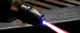
Used simultaneously for welding metals. exposure to an arc discharge and plasma jet, which allows deep penetration into the metal. This type of welding is characterized by high productivity and, due to the high stability of the arc, good quality; allows you to weld fairly thick metal (10–15 mm) without special equipment. cutting edges. A low-power plasma arc at currents of 0.1–40 A is convenient for welding thin sheets (0.05 mm) in the manufacture of membranes, bellows, and heat exchangers from Ta, Ti, Mo, W, Al.
Metal cutting is carried out simultaneously. exposure to a plasma jet and arc discharge between the anode (metal being cut) and the cathode of the plasmatron. A plasma jet (Ar, N2, H2, NH3 and their mixtures) is formed and stabilized in the anode channel when heated by an arc discharge. To intensify the cutting of metals, chemically active plasma is used. For example, when cutting air. plasma oxygen, oxidizing the metal, gives additional. energetic contribution to the cutting process. Plasma arcs are used to cut stainless and chromium-nickel steels, Cu, Al and other metals and alloys that are not amenable to oxygen cutting. Non-conductive materials (concrete, granite, thin-sheet organic materials) are treated with a plasma jet.
To apply coatings, the material (refractory metals, oxides, carbides, silicides, borides, etc.) is introduced in the form of wire, powder or suspension into a plasma jet, in which it melts, sprays and is applied in the form of small particles at high speed to the surface of the product ( substrate). High velocities of sprayed particles (up to 700 m/s) determine the formation of coatings on the substrate in the form of disks of small thickness (2–10 μm) and their high cooling rate - up to 108 K/s; depending on the sprayed material, an amorphous or nanostructure with high microhardness is formed in the coating. With separate solidification of sprayed particles on the substrate, it is possible to design the macrostructure of the coating, including the creation of three-dimensional capillary-porous coatings (porosity determines the low apparent modulus of elasticity of the coating, which ensures high thermal stability of heat-protective coatings). Increasing the substrate temperature significantly increases the cohesion and adhesion of coatings. Basic The area of application of plasma spraying is the formation of heat-protective oxide coatings with porosity up to 20% or dense coatings with cracks perpendicular to the substrate. Plasma spraying is also successfully used to produce fibrous compositions. materials with aluminum, titanium and intermetallic matrices.
Etching using gas discharge plasma components is used to remove substances from a surface (eg a workpiece). Plasma etching is sometimes called “dry” in contrast to classical etching. “wet”, associated with the use of liquid etchants. The advantage of plasma etching over liquid etching (in addition to significantly lower consumption of reagents) is the possibility of precision dimensional processing of products and complete automation of the process.
P. t. is also used to obtain spherical powders. particle shape used in powder metallurgy. A material is introduced into the plasma jet, the particles of which, when melted, become spherical under the action of surface tension forces. form. The particle size can be adjusted from a few microns to 1 mm. Smaller (ultradisperse) powders with particle sizes of 10 nm and above are obtained by evaporation of the starting material in plasma and its subsequent condensation.
Lecture No. 7. PLASMA TREATMENT
Introduction
In 1923, American physicists L. Tonks and I. Langmuir proposed calling a medium in which a significant part of the molecules or atoms is ionized plasma. Plasma is the state of matter most common in space.
Plasma is most often produced in an electric arc discharge, in a high-frequency electric field, using laser radiation energy.
The physical properties of plasma - high temperatures, enthalpy and electrical conductivity - allow for a number of interesting physical and technical projects.
In atomic physics, for example, “hot” plasma with a temperature above K is considered as a means of conducting controlled thermonuclear fusion reactions.
There are a number of magnetohydrodynamic (
MHD) generators, in which a high-speed plasma flow serves to directly convert thermal energy into electrical energy.
There are electric jet plasma engines.
Plasma has found application in metallurgy and welding.
For technological purposes, the so-called “low-temperature” plasma with a temperature of ... K, which is a partially ionized gas, is used.
Plasma torches or plasma torches have been developed to produce plasma.
In arc plasma torches, plasma with the required characteristics can be obtained by various types of interaction of the arc with the plasma-forming gas: argon, helium, nitrogen, hydrogen, oxygen and air [1].
Stabilization of the arc in the plasma torch can be carried out by an axial gas flow 1, creating a layer 2 limiting the arc discharge column.
When gas is supplied tangentially into the arc chamber of the plasma torch, arc stabilization is achieved due to the vortex flow 1 of the plasma-forming gas.
Figure 7.1 — Scheme Figure 7.2 — Scheme
tangential gas arc stabilization
axial flow 1 – vortex gas flow. 1- gas; 2 – gas layer.
A very effective way to stabilize the arc discharge in a plasmatron and increase its specific energy characteristics is to limit the diameter of the arc discharge column by a cooled wall (the figure will be below).
The plasma-forming gas used in the plasma torch largely determines the technological capabilities of the plasma jet, and it must be selected depending on the goals of the process.
Molecular gases - nitrogen, hydrogen, oxygen and air can increase the heating efficiency due to dissociation (decomposition)-association (combination) reactions. In this case, additional heat absorption occurs in the arc discharge column.
When it hits the surface being treated, the plasma-forming gas associates (transforms from atomic to molecular); in this case, the heat spent on its dissociation is released.
1. Basic physical characteristics and properties of plasma
1.1 Degree of plasma ionization
This is a quantitative characteristic that determines the ratio of charged neutral particles in the plasma:
X = n/N
(7.1)
where n
– concentration in plasma of charged particles of the same sign (ions or electrons);
N
– the number of neutral molecules or atoms of a gas before its ionization.
The degree of plasma ionization depends on many factors (primarily temperature). For low-temperature plasma, its value can vary within wide limits - 0...100%.
1.2 Quasineutrality
Quasineutrality of plasma means that in a certain volume the number of negatively charged electron particles is equal to the number of positively charged ion particles, otherwise electric fields must arise, leading to charge redistribution.
As the pressure decreases, the number of particles in the volume decreases and a moment may come when the number of particles is so small that the quasi-neutrality conditions are not satisfied.
The volume where the quasineutrality of the plasma is violated is determined by the Debye radius (on behalf of the Dutch physicist P. Debye):
, (7.2)
where is temperature (electronic), K;
– electron concentration, cm-3.
If the dimensions of the plasma region under consideration are greater than the Debye radius, the quasineutrality condition is satisfied ( ), that is, the concentrations of charged electrons and ions in the plasma are equal.
If we consider a volume of plasma with radius r
less than , in this volume the plasma cannot be considered quasi-neutral.
The concept of quasi-neutrality allows us to more clearly define plasma as a form of matter in which the number of electrons and ions in the volume is so large that even a slight violation of equality is impossible due to the formation of strong electric fields. In real plasma devices used for technological purposes and in vacuum, the value is determined by the values ... cm .
1.3 Plasma temperature
The plasma temperature is the most important characteristic, and in real plasmatrons it can reach (2...5)·104 K. In a number of cases, plasma can be considered as an ideal gas, since at high temperatures the concentration of particles in the plasma, despite relatively high pressures, is small and the ideal gas equation, including the basic law of the gas state, can be considered valid for it:
P
∙V=
R∙T
(7.3)
where p
– gas pressure, Pa;
V – volume, m3;
T
– temperature, K;
R
– universal gas constant, (
R
= 8.31 J/mol K).
For plasma, it is more convenient to present this equation in the following form:
, (7.4)
where is the total concentration of charged and neutral particles in the plasma;
N
– Avogadro’s number (
N
= 6.02· – the number of molecules or atoms in 1
mole
of a substance).
A mole is the amount of substance in a system containing the same number of structural elements as there are so many atoms in carbon - 12 with a mass of 0.012 kg.
Avogadro's law, discovered in 1811 by an Italian physicist and chemist, states that equal volumes of ideal gases at the same pressures and temperatures contain the same number of molecules.
When considering plasma as a collection of charged particles of different signs (electron – “–” and ions – “+”), the concept is introduced:
— electron temperature — ;
— ion temperature — .
This approach allows us to consider in more detail the energy of individual particles that make up the plasma.
Unlike an ordinary gas mixture, all particles of which have the same average kinematic energy of random thermal motion, this energy is different for electrons, ions and neutral atoms.
The electron temperature (electron energy) is always higher than the energy of ions and neutral atoms due to the greater mobility of the electron.
As the density (pressure) of the plasma decreases, the difference between the electron temperature and ion temperature can reach several orders of magnitude.
For plasma used in technological devices, where the pressure is quite high and the concentration of particles is more than cm-3, it can be assumed with sufficient accuracy for practical purposes that , that is, the temperatures of all particles are equal.
Such plasma is called thermal.
Figure 7.3 - Dependence of temperatures on pressure (plasma density)
1.4. Plasma enthalpy
This is an important energy characteristic of the plasma jet and depends on both the temperature and the type of plasma-forming gas used.
The enthalpy of monoatomic gases increases with increasing temperature due to an increase in the energy of thermal motion of gas atoms and their ionization.
For molecular gases, during heating, the enthalpy of the gas, even at relatively low temperatures, increases sharply due to the dissociation process, and then the enthalpy begins to increase due to ionization.
Therefore, for technological processes when very high temperatures (over 104 K)
), it is advisable to use nitrogen, hydrogen, oxygen and air as plasma-forming gases.
To obtain higher temperatures, it is necessary to use plasma of monatomic gases (argon, helium).
The entropy of the plasma flow is strongly influenced by the flow rate of the plasma-forming gas. An increase in gas flow rate usually leads to a decrease in the efficiency of heat transfer from the arc or high-frequency discharge to the gas cathode, and the enthalpy of the gas decreases.
In technological processes, a hydrogen-nitrogen or hydrogen-argon mixture of gases is used, in which the volumetric content of hydrogen is 10...20%.
1.5. Types of plasma energy sources
When parts are heated by plasma, energy transfer can be carried out either only due to the processes of heat exchange of heated gas with a solid or liquid phase (the part is not electrically connected to the power source), or due to the total effect of heat exchange and electrical interaction of charged plasma particles with the workpiece electrode.
In this regard, in the practice of plasma technology, three main principal diagrams of plasma torches have emerged.
In two schemes (Figure 7.4 a, b
) an electric arc discharge is used to produce plasma;
in the circuit (Figure 7.4 c
), heating of the gas and formation of plasma is carried out due to an electrodeless (high-frequency induction discharge.
Figure 7.4 — Basic diagrams of plasma torches
a – direct action; b – indirect action; c – plasmatron with high-frequency induction discharge.
Scheme ( a
) was called a plasma arc, and the plasma torch for its production was called a direct plasma torch.
In circuit (b
), product 1 is not galvanically connected to the electrode, therefore the circuit is called a plasma jet, and the plasma torch is called an indirect plasma torch.
1.6 Characteristics of the plasma source
The main characteristics of a plasma energy source are its effective thermal power and concentration coefficient, which determines the distribution of the specific heat flux over the surface of the workpiece.
For a plasma arc, the effective thermal power is equal to:
, W
where U
– arc voltage, V;
I
– arc current strength, A;
– effective efficiency of the plasma heating process, taking into account energy losses during its transfer to the product.
Figure 7.5 — Temperature distribution of the plasma arc (a) and plasma jet (b) along the radius r
and along the length
l
Temperature distribution of the plasma arc and plasma jet along the radius ( r
) and along the length ( ) are extremely uneven. The maximum temperature is observed in the center on the axis of the plasma flow, and it is significantly higher than that of an open arc.
The heat flux density for plasma energy sources is also higher than for an open arc, and reaches W/cm2.
Heating the gas in the plasmatron leads to a sharp decrease in gas density. Due to this, the speed of its expiration increases. The flow rate is maximum in the center, where there is a maximum temperature and a minimum mass flow of gas. The maximum temperature is 17000 °C, and the maximum speed reaches 2 km/s.
The high speed of plasma flow when it exits the plasma torch allows one to obtain a significant gas-dynamic pressure, which grows with increasing current strength.
In most cases, the gas flow rate in the plasmatron exceeds 1 l/s and the flow of hot gas is turbulent.
Reducing the gas flow rate to less than 0.1 l/s makes it possible to obtain laminar plasma jets that are longer (up to 0.4 m) and highly stable.
In a plasma flow, you can obtain almost any substance in the molecular or vapor phase. Plasma heating makes it possible to obtain nitrides and carbides, oxides of refractory metals and non-metals of high purity in the vapor phase. In this case, it is possible to significantly increase the yield of reaction products compared to other methods of carrying out chemical reactions.
An example of such processes is the plasma-chemical production of boron-based abrasive materials, the deposition of titanium nitride on the working surface of a metal-cutting tool, etc.
2. Plasma processing technology
2.1 Plasma heating
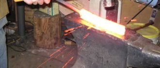
Heating parts and materials to low temperatures (below their melting point) using plasma torches is used relatively rarely, but recently plasma-mechanical processing of metals, where such heating is carried out, has been increasingly used. The essence of the method is that when processing, for example, cutting high-strength metals and alloys, a plasma torch is installed in front of the cutter, heating a narrow zone of the material being processed.
Strength decreases and ductility increases. You can increase the depth of cut and feed without compromising surface quality. No surface oxidation.
The use of plasma heating when turning cylindrical workpieces with a diameter of 100...350 mm from heat-resistant nickel alloys, tungsten and molybdenum has shown that processing productivity increases by 6...8 times while reducing cutter wear by 5...6 times. The metal removal rate can reach 3…4 kg/min .
Plasma heating to higher temperatures can lead to melting of the roughness of a machined surface, thereby improving technological performance.
2.2 Melting of matter
Melting of metals and alloys, as well as non-metallic materials using plasma heating has become widespread. This method is characterized by high stability, simplicity and flexibility of the technological process. Plasma melting allows the use of a wide variety of media and starting materials with minimal losses of alloying components.
Figure 7.6 — Diagram of a furnace for melting into a water-cooled crystallizer
The most common furnace design is for melting into a water-cooled crystallizer. Complex alloys, such as tool alloys, are usually smelted in such furnaces. At the same time, due to the small content of non-metallic inclusions in the metal in the form of oxides and oxygen, its mechanical properties (especially ductility) are noticeably increased.
Plasma heating is also used for melting metal, followed by grinding the melt and crystallizing it in the form of small droplets.
Figure 7.7 - Scheme of melting to produce small-sized droplets
1 – crucible; 2 – crystallizer.
Plasma heating is also used for melting metal, followed by grinding the melt and crystallizing it in the form of small droplets.
In the future, this material is used as the starting product of powder metallurgy, for surfacing, etc.
Grinding of metal is most often achieved by spraying molten metal while rotating crucible 1. Falling on the cold walls of crystallizer 2, drops of liquid metal solidify and collect in the form of granules at the bottom of the chamber, and the high cooling rate of the molten metal makes it possible to obtain nonequilibrium structures with specific properties.
2.3 Welding and surfacing
Welding using plasma energy sources is being used more and more widely, so compared to a conventional free-burning electric arc, it is possible to obtain a greater depth of penetration and a smaller weld width and, accordingly, a narrower heat-affected zone. The process proceeds at a faster rate as the quality of the weld improves.
Plasma welding is used to weld parts up to 20 mm thick in one pass, which makes it possible to significantly increase the productivity of the process, reduce the deformations occurring during welding and ultimately obtain a more efficient welded joint.
Microplasma welding is a type of plasma welding process and is characterized by a plasma current of the order of 0.1...10 A. The thickness of the workpieces being welded is usually 0.025...1.0 mm (foil) - it is impossible to weld by other methods (electronic equipment parts).
Plasma surfacing is used to apply surface layers to workpieces (most often made of metals and alloys that differ in composition from the substrate material) in order to improve the performance properties of the parts. For surfacing, materials with special properties (high hardness, increased wear resistance, corrosion and heat resistance) are usually used.
Surfacing makes it possible to produce products from cheap structural materials with a rational distribution of properties among individual elements.
At the same time, the consumption of expensive alloying materials is significantly reduced. The thickness of the layers deposited in one pass can reach 4...5 mm; multi-layer surfacing is possible.
Surfacing is carried out using a plasma jet, which makes it possible to regulate the depth of penetration of the base metal by changing the distance between the torch and the workpiece. To ensure protection of the molten metal bath from interaction with atmospheric gases, argon and hydrogen are used as plasma-forming gases.
Surfacing of working tool blades allows saving scarce and expensive tool steels (P18, P6M5). The mass of deposited tool steel (on ordinary carbon steel) usually does not exceed 4...5% of the total mass of the tool.
With the help of plasma surfacing, expensive components and parts (dies, molds, rolls, etc.) of metalworking equipment are restored for repair purposes.
2.4 Sputtering
There are two main types of process:
— supply of material to the plasmatron in the form of a rod or wire;
— supply of material to the plasmatron in the form of powder (oxides, nitrides, carbides).
Plasma spraying usually produces a thin layer (... m).
Metal coatings obtained using plasma spraying most often consist of tungsten, molybdenum, nickel, cobalt and other metals and alloys with a fairly high melting point.
The productivity of the process can reach several sprayed materials per hour, and the density of the sprayed layer is usually 80...90% of the density of the monolithic metal. Thin (up to 0.1...0.3 mm) sprayed layers have a higher density and better adhesion to the sprayed sublayer than thicker ones.
Coatings are different depending on their purpose: heat-resistant, corrosion-resistant, protective. For the latter, aluminum and zirconium oxides are used.
Spraying increases the durability of chill molds and casting molds; The wear resistance of dies for drawing (drawing) molybdenum rods during spraying increases by 5...10 times.
One of the varieties of the plasma spraying process is ion coating technology using plasma accelerators.
Figure 7.8 — Scheme of ionic coating technology
1 – water-cooled cathode; 2 – plasma; 3 – surface to be treated.
In industry, ion technology is used to increase the service life of metal cutting tools and dies. At the same time, the wear resistance of the tool increases by 2...5 times.
The coating material is obtained by evaporation in a vacuum of a water-cooled cathode 1. Then it is ionized in an electrical discharge and converted into plasma 2, which is accelerated using an electromagnetic field and focused into a flow towards the treated surface 3.
The significant energy that can be imparted to ions in plasma allows them to be deeply embedded in the surfaces being processed and to obtain durable surface coatings (and metal films).
Plasma molding of parts using sputtering produces thin-walled parts and blanks of complex geometric shapes from difficult-to-process metals (tungsten, molybdenum). The material in the form of plasma is sprayed onto mandrels or templates, which can subsequently either be dissolved chemically (if they are made of aluminum or copper) or disassembled into parts.
As a rule, the layer obtained after spraying is fragile and has a layered structure. After annealing, it acquires an equilibrium fine-grained structure and mechanical properties that allow it to be machined and used in structures.
Plasma spray molding is used for crucibles, rocket engine parts, and MHD generators.
2.5 Cutting
This is thermal cutting, independent of the properties of the materials being cut. Possibility of cutting workpieces of considerable thickness (up to 250...300 mm), obtaining cuts of any configuration.
There are two main types of plasma cutting: separation and surface gouging (Figure 7.9.)
For manual work, a voltage of 180 V is used, for machine work - 500 V.
When planing and turning (to remove the deformed layer), the plasma head is placed at an angle of 40...60° to the surface being processed.
Microplasma cutting uses a current of 5...100 A to cut workpieces 6...8 mm thick. In this case, the cutting width is no more than 0.8...1.0 mm.
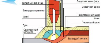
Figure 7.9. — Diagram of the plasma head: 1 – blank; 2 – plasma jet; 3 – arc discharge; 4 – copper water-cooled electrode; 5 – tungsten electrode.
3. Test questions
1. What is plasma?
2. How does a plasma arc differ from a free-burning electric arc?
3. What are the main physical characteristics of plasma?
4. What are the main physicochemical effects during the interaction of plasma with matter?
5. When did the term “plasma” appear?
6. Basic diagrams of plasma torches.
7. What effect does plasma treatment have on surface hardening?
8. What is the essence of plasma cutting and gouging processes?
9. In what cases is it advisable to use plasma heating when cutting metals?
10. For which products is plasma surface forming used?
11. In what cases is it advisable to use plasma gouging?
Cementation versus PulsPlasma - nitriding
Methods of strengthening metals and alloys were carried out by a student of the group
From the listed data, it becomes clear that PulsPlasma - nitriding is an alternative to classical methods of chemical-thermal surface hardening such as carburization, nitriding and carbonitriding in molten salts or gas nitriding.
Another aspect that has not yet been covered is the economic aspect. A practical example shows that it is advisable to reconsider the process of manufacturing parts in such a way as to abandon energy- and economically expensive carburization in favor of PulsPlasma nitriding.
It is necessary to take into account that such properties of the surface layer as surface hardness, wear resistance, and endurance limit after nitriding are similarly high, and in some cases even significantly better, than after carburization. As for the small depths of the nitrided layer compared to the cemented layer, it should be noted that due to temperature deformations and changes in dimensions after carburization, additional mechanical processing of the parts is necessary
This leads to a decrease in the thickness of the cemented layer. Strength requirements that will ensure high performance characteristics of parts can be achieved using nitriding thanks to the correct selection of the appropriate material
As for the small depths of the nitrided layer compared to the cemented layer, it should be noted that due to temperature deformations and changes in size after carburization, additional mechanical processing of the parts is necessary. This leads to a decrease in the thickness of the cemented layer. Strength requirements that will ensure high performance characteristics of parts can be achieved using nitriding thanks to the correct selection of the appropriate material.
The table shows, as an example, the option of using a part after PulsPlasma nitriding instead of a cemented gear of a printing machine made of 15 CrNi 6 E steel. The steel for nitriding was first determined by calculation and confirmed by testing.
Table 3 Calculation of the strength of gears made of different materials after carburization and PulsPlasma nitriding
As a result of using nitriding instead of carburization, in addition to increasing the service life of the gear, an economic effect of up to 30% was achieved in the manufacture of the part.
Diagram 1 Comparison of the cost of manufacturing a part by carburizing and PulsPlasma - nitriding
Technological process of plasma treatment (polishing) for a semi-automated line
Before polishing, the product can be prepared by abrasive mechanical grinding (for example, using sandblasting, drum or vibration). This will reduce the time of electrolytic plasma polishing in the presence of burrs and other defects of the product.
Plasma polishing takes place in 7 main stages:
- Preparing the part for processing
- Manual suspension loading
- Automated operations: energizing raised suspension
- slow descent into electrolyte
- exposure 2–5 minutes
- suspension lift with parts
- power cut
The product is installed on a special suspension, ensuring reliable electrical contact. Then the operating voltage is applied, and the part is slowly immersed in the preheated electrolyte.
Existing plasma cutting methods
All existing plasma cutting methods can be divided into jet and arc. Moreover, it does not matter at all whether a manual cutter is used or a CNC plasma cutting and cutting machine. In the first case, all the necessary conditions for gas ionization are implemented in the cutter itself. Such a device can process almost any material (metals and non-metals). In the second case, the material being processed must have electrical conductivity (otherwise an electric arc will not occur and gas ionization will occur).
In addition to differences in the method of plasma formation, plasma processing can also be classified according to the technological features of cutting into simple (without the use of auxiliary substances), processing with water and processing in a protective gas environment. The last two methods allow you to significantly increase the cutting speed without fear of metal oxidation.