Types of welding seams
What types of welds are there? According to engineering design, all welding seams are divided into four main groups:
There are a number of types of welds depending on the type of connection:
- a butt joint seam, when two workpieces with straight ends are butted together and welded into a circular seam with an even seam;
- seam on a T-beam or I-beam. Often used in the production of iron piles or rails;
- overlapping joint seam, when one welded piece lies on top;
- a seam of connections that are located at an angle relative to each other.
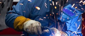
Welding electrodes are the main consumables for most types of welding, but the most basic method with which welding work is carried out with electrodes is the electric arc welding method.
Welding machines of any kind, inverter or semi-automatic, are high-quality equipment, but sooner or later the time comes to repair it and remove any faults that have arisen. Read more about repairing welding machines.
What options are used?
Methods for welding circumferential seams depend on the diameter of the pipe itself. Currently there are 2 solutions in use:
- Joints of rings with a diameter of up to 300 mm should be made using a reverse-step method . This is a multi-layer type of welding work, which consists of overlapping the initial and final adjacent layers. The process changes the direction of application to improve reliability.
- With a diameter of 300 and above, it is better to use the “Cross-cross” technique . It is carried out by two specialists with preliminary markings. 8 equal points are applied, which are welded in 2 sections. This allows you to create an ideal weld surface and ensure high strength.
The process of welding circumferential seams is determined by the consumables and equipment used.
Welding ceiling seams
The laying of the ceiling seam occurs in two technological stages, the first of which is welding of the root seam.
For this, as a rule, a “troika” electrode is used - 3 mm. and low current with increasing voltage.
Depending on the conditions in which the work will be carried out, welding work can be performed using two methods:
- If possible, it is advisable to lay the ceiling seam with short, abrupt seams. The thing is that the weld pool is held in the seam only due to the forces of surface tension; if the mass of the seam exceeds these forces, the molten metal will spill down. Separate welding is required at the beginning and end of the common seam (the roots of the seam). Afterwards, it is necessary to weld the metal plates on the reverse side - the ceiling roller - welding the horizontal seams;
- if possible, it is better to weld the metal in the ceiling position using the shortest possible arc. In this case, the metal will solidify into a red-hot, rigid formation immediately after the arc is withdrawn.
To ensure that the seam is not very convex and does not protrude above the level of the metal, it is necessary to maintain a constant welding speed. Vertical seams are welded in exactly the same way.
About the use of electric welding
When joining pipes with a wall thickness of 3 mm or more, electric welding is usually used. During the installation of main pipelines, one of two schemes is used for this:
- pipes are routed to their future location, after which they are connected using modern butt joint machines;
- Single pipe products are welded into sections at specialized bases, after which the prepared structures are transported to the route, where they are connected into a continuous network.
In practice, the second method is more often used.
The calibrated ends of single pipes, ready for welding, are centered using clamps, clamps and other assembly devices. After checking such an assembly, the joints are grabbed in three places. If work is carried out with pipes of large diameters, such tacks are placed at a distance of 35-40 cm from each other (then their number can increase). Domestic specialists, as a rule, use multilayer welding in such cases - this has a positive effect on both the structure and the density of the seam.
Welding fillet welds
When welding a corner joint, you can use different techniques depending on the angle:
- two workpieces are located perpendicularly. In this case, only the inner joint itself can be welded, since the area of the main force for bending and tearing is located here. When welding tubes located at an angle, it is necessary to make a concentric seam around the circumference;
- angle 60 degrees or less. In this case, two workpieces are completely boiled on both sides. It is prohibited to weld such joints using tack welds.
Mechanical joint tracking system
The automatic welding head is mounted on a cross slider (sliding support) with a drive movement of 100 mm in the vertical and horizontal planes. The slider drive is two electric DC motors with lead screws and ball screws. The cross slider is controlled from a portable control panel.
The welding head is equipped with a contact-type mechanical vertical joint tracking system, which ensures constant ejection of the welding wire from the current-carrying nozzle.
Additionally, the welding head is equipped with a point laser designator to facilitate tracking of the weld joint. The target designator projects a light point with a diameter of less than 2 mm at a distance of 50 to 200 mm.
Welding circumferential seams
Cylinders, shafts, round tanks, barrels and other cylindrical spare parts and products are an area in which the use of circumferential welding seams is widespread.
Since welding of cylindrical products and laying of circumferential seams is often used in the production of elbow and straight pipes, the process is often automated - resistance seam welding.
But, if the seam is made by hand, then the following technology must be followed:
It is necessary to weld the seam only from the outside, this is explained by the elementary inaccessibility of laying the seam inside the pipeline. In the case of welding shafts, preliminary end brazing can be done. The depth of the seam should not exceed 5-6 mm.
Submerged arc welding is a high-quality method of joining two metals using electric arc welding, when the melt pool - the weld pool is protected from atmospheric air by a layer of powdered flux.
Read about aluminum cutting here.
Where can I order equipment and consumables?
To order professional equipment or consumables, we recommend contacting the Intera online store. This is a professional company that has been engaged in core activities for a long period of time. The interaction is accompanied by:
- Nice prices and discounts for customers;
- Fast and friendly service;
- A good assortment with constant updating of positions;
- Professional support and assistance.
To buy equipment for welding circumferential seams in the Intera store, leave a request online or call the numbers listed on the website. You can also visit our offline store at the address: Rostov-on-Don, st. Taganrogskaya, 144 .
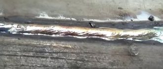
Cleaning welds after welding
After laying the weld, it is necessary to clean the seam in order to remove slag and scale. Cleaning weld seams is carried out in three stages:
Cleaning the area around the seam. It is necessary to clean the entire surface of the metal around the seam, since during the welding process scale or droplets of hot metal could get onto the surface of the metal. They need to be beaten off with a chisel or hammer. After this, you can treat the surface with an antioxidant compound.
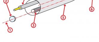
Welding chamfers
When joining thick pipe blanks, the formed seam should be made thicker than the part itself . To form a connection with the specified geometric parameters, it is necessary to cut the edges by chamfering. After this, the electrode will be provided with access for high-quality welding of the seam to the full depth.
The main chamfer parameters are:
- Gap b. the distance between the workpieces is up to 2-3 mm.
- Blunt C. The part of the edge that is not beveled. it is left in place to reduce the likelihood of burning through the root of the seam..
- Bevel angle β. With double-sided cutting, the acute angle takes values of 15-30°, with one-sided cutting, up to 45°.
- Cutting angle α. An obtuse angle is equal to twice the bevel angle and provides proper access to the root of the weld for welding equipment.
Chamfer options.
If the dullness value is small or non-existent, then burn-through is prevented by such methods as:
- the use of linings that prevent the flow of molten metal;
- flux pad welding;
- pre-cooking;
- execution of the lock.
Technologists should pay special attention to the correct calculation and compliance with the optimal cutting parameters . This allows you to reduce labor intensity, use materials sparingly and maintain cost control.
When preparing butt joints, the type of chamfer depends on the thickness of the parts:
- 3-25mm: one-sided chamfer;
- 26-60mm: double-sided;
The following boundaries are set for corners:
- 3-20mm: one-sided;
- 21-50 mm: double-sided.
Based on the geometric shape of the cross-sectional profile, the following types of cutting are distinguished:
- regular bevel, profile is a trapezoid,
- X-shaped, two bevels are made towards each other in such a way that the cross-sectional profile of the double-sided cut visually resembles the outline of the letter X;
- U-shaped, the cross-sectional profile is curvilinear and resembles the outline of the letter U.
GOST for pipe welding recommends using a U-shaped groove for large workpiece thicknesses , in order to reduce the cross-sectional area of the seam and, therefore, reduce material consumption and increase work speed.
The cutting shape is chosen based on the thickness of the pipes:
- 3-25mm: X-shaped or V-shaped;
- 26-60mm - U-shaped;
- more than 60 mm - special forms.
They are:
- ledges;
- complex curvilinear profiles designed to maintain access of the electrode to the root of the seam and reduce the cross-sectional area.
The following methods are used for cutting:
- Gas cutting . Characterized by low accuracy and insufficient surface quality. Requires additional processing by mechanical means.
- Machining . Planing or milling gives sufficient surface cleanliness and shape. Slotting also requires finishing machining.
Welding defects
As a rule, defects in welding seams arise due to non-compliance with welding technological standards, poor-quality electrodes, the occurrence of stray currents and the entry of atomic air particles into the weld pool.
All weld defects are compiled into a single standard, which sets technical requirements for welding joints.
The standard also regulates the control of welding seams, which includes technical testing and sound flaw detection.
According to this standard, defects in welded joints are divided into six groups:
- cracked seams, cracks;
- craters and holes, fistulas that are formed by the process of sparking and cavities in the weld pool;
- solid inclusions – electrode scale, metal spasms;
- unwelded areas, lack of metal connection;
- seam shape that does not meet the welding technology.
These defects stand out as the main ones.
Welding seams are permanent connections of metals, therefore increased demands are placed on the production of welded seams.
Compliance with all standards and technology will allow you to lay high-quality and reliable seams of any category.
GOST 16037-80 for welded joints using manual arc welding
Manual arc welding of pipes remains one of the most common methods of installing pipeline systems, which are both independent transport and distribution networks and components of process equipment. High quality joints of pipeline systems is the key to their safe operation.
Welding methods, types of joints, geometric parameters and standard dimensions, as well as methods of cutting edges - all this is regulated in GOST 16037-80 manual arc welding of welded joints. Strict adherence to the requirements of the standard in the design, formation of the technological process and welding of steel pipelines ensures the required level of quality.
Welding equipment PLASMA-TIG
2.1. DESCRIPTION OF BASIC EQUIPMENT FOR PLASMA-TIG WELDING
The offered equipment provides the highest quality of PLASMA welding of all thicknesses in the range from 2.5 to 8 mm without cutting edges, and below 2.5 mm - using the TIG DC method.
Multi-process welding machine for the following types of welding:
- TIG welding with smooth or pulsed direct current.
- Plasma welding with smooth or pulsed direct current.
- TIG welding with alternating current of variable polarity
Main components of the system:
- Welding control panel
- Welding source NERTAMATIC 450
- RF unit and burner connection interface
- Control cables 10, 17, 22 or 25 m long
The installation controls current and voltage parameters, wire and gas supply, controls arc voltage, controls welding movement, oscillation and magnetic deflection of the welding arc.
2.2 WELDING CONTROL PANEL NERTAMATIC PLUS or HPM
Standard control - NERTAMATIC PLUS
The welding process control panel provides full control of the welding cycle in plasma or TIG welding mode. Using the LCD monitor, keys and data input system, the welding cycle is programmed, its parameters are changed during welding and the welding parameters are displayed.
For the welding process, the start and end of the cycle, emergency stop of the cycle, gas purging, adjustment of wire feed and arc voltage are carried out.
This module is connected to the NERTAMATIC 450 central power supply unit via a fiber optic cable and can be located at a distance of up to 25 m from it. It is usually installed next to the welding head.
HPW Control
A control device for complete control of the start-up of the device from only one control panel, allowing:
- Digital control of the welding process, associated movements and drives.
- Traceability, the program includes all parameters to ensure repeatable welding.
- Optional quality control system, recording and saving the most important welding parameters (current, voltage, wire feed, movement).
- User-friendly, intuitive interface for programming, control and monitoring.
- Intuitive cycle design thanks to graphical programming.
- Touch screen
for easy use of HPW. - Independent programming on PC, data exchange via USB.
- Optimization of the device layout.
- Control via industrial PC.
For welding thicknesses over 2.5 mm using the PLASMA method, the Key-Hole technology is used (the so-called “keyhole”).
When the welding arc suddenly breaks, a hole usually remains on the product. To neutralize this drawback when welding circumferential seams and to eliminate the hole, before turning off the arc, it is necessary to gradually reduce the gas supply to the welding head simultaneously with the arc current. This gas control is implemented by the NERTAMATIC PLUS system and gas reducers controlled in a closed loop
, with measuring the weight of the gas entering the system and comparing the obtained value with the specified and subsequent adjustment of the gearbox, taking into account the programmed value.
Adjustable parameters: pilot arc gas flow, gas supply before welding, gas supply delay time, welding gas, decay time, gas supply after welding.
Movements during the welding process are controlled by an analog system +/- 10V or on the on/off principle. on command from the limit switches. Adjustable parameters: diameter of the part being welded, movement speed, welding time, time for the closing seam.
2.3. WELDING SOURCE NERTAMATIC 450
The NERTAMATIC 450 power supply is equipped with:
- Central module
- Interface for: Facilitating its integration into the machine environment via an external PLC (open PLC mode)
- Providing (via software installed on a PC) access to program files, the ability to edit programs, export programs to an Excel file for printing and storage.
MAIN CHARACTERISTICS
The power source uses transistor technology with a chopper, specially designed for TIG or plasma welding, the parameters are not affected by power supply fluctuations + 10%.
- Welding current:
3 - 450 A - Duty cycle:
100% at 450A and 40°C - Pulse frequency:
1 – 1000 Hz. - No load voltage:
110V - Pilot arc current:
7 - 25 A / 100% - Supply voltage:
230 / 400 / 415 / 440 V - 3 ph., 50-60 Hz
Auxiliary power supplies:
- 230V f. (6A) for water cooling of welding torch
- 42V 30A internal for power regulators
Welding cables with a length of 10, 17, 22 or 25 m are supplied with the installation.
2.4. CONNECTION OF HF AND BURNER
This is an element of interaction between the hose package connected to the power source and the welding torch. It includes an RF connection to ignite the pilot arc in plasma welding mode and the welding arc in TIG welding mode.
The connectors for connecting the torch are quick-release, which ensures a quick change of torches to convert equipment from Plasma to TIG welding and vice versa.
2.5. TORCH SP7 FOR PLASMA WELDING
Combines performance and reliability with simplicity of design.
Welding torch for automatic plasma welding, standard or with two gas flows for TIG welding.
The SP7 torch can withstand the harshest arc conditions. The main advantages of this torch, which provides 100% duty cycle at 450A: Ease of plasma welding:
- self-centering of the electrode in the nozzle,
- the electrode holder is independent of the torch hose package, provides easy adjustment of the position of the tungsten electrode,
- tip movement for quick assembly without disassembling the nozzle (optimal side channel position).
Reliable operation:
- long nozzle life due to optimized cooling system and monolithic design,
- excellent protection and cooling of the electrode,
- welding of carbon steel, stainless steel, alloy steel and noble metals such as titanium, zirconium.
2.6. AUXILIARY GASES CONTROL UNIT
This gas module can control 2 gas circuits on a welding installation, for example, protective gases of the torch and trailer to protect the cooling seam or backflow
The standard version provides a flow rate of 10-38 l/min, is equipped with a solenoid valve and a gas pressure control system.
2.7. ARC VOLTAGE CONTROL (AVC) The average arc length in plasma welding, or more precisely the distance between the torch and the workpiece, is 7 mm + 2 mm depending on the thickness of the sheet being welded. The quality of the seam is not affected by changes in distance less than 1 mm. When TIG welding, the arc is shorter, from 1.5 to 3 mm, so the tolerance is even tighter. This device provides automatic regulation of the burner position within permissible deviations. OPERATING PRINCIPLE
In automatic TIG or plasma welding, the arc voltage directly depends on the distance between the electrode and the part being welded, all other parameters are constant (current, type and gas supply speed). Maintaining the distance between the electrode and the workpiece is equivalent to maintaining a constant arc voltage value. This function is performed by controlling the drive rail on which the welding torch is mounted.
Moreover, this feature provides:
- automatic arc firing sequence by controlling the lowering and raising of the torch at the end of the welding cycle.
Equipment controlled by NERTAMATIC 450 includes:
- 1 speed controller in NERTAMATIC source
- 1 package of cables 10.17, 22 or 25 m long
- 1 mechanical structure including: 1 vertical slider with drive, stroke 200mm
- 1 cylinder support for rotation around a vertical axis with quick burner lock
- 1 manual slider with a stroke of 50mm at the bottom of the cylinder caliper.
- 1 burner support.
2.8. WIRE FEEDING MECHANISM
The device uses the principle of “pushing” the wire through a flexible hose to the point where the wire enters the welding arc. The wire feed speed is adjustable with an error of + 1% and can be programmed from 0.15 to 6 m per minute in welding mode. In manual mode, wire feeding can be carried out at either low or high speed.
Feeding of steel wire Ø 1.0 and 1.2 as standard and 0.8 as an option is provided. It is also possible to use aluminum or titanium wire Ø 1.2 and 1.6 as an option.
The installation consists of the following elements:
- 1 speed controller in NERTAMATIC source
- 1 package of cables 10.17, 22 or 25 m long
- 1 mechanical structure including:
- 1 support axle with a protective box for wire cassettes Æ 300mm, 15 kg.
- Wire feed channel
- 1 gear motor.
- 1 set of accessories for feeding steel wire Ø 1.0 and 1.2 mm
- 1 mechanical device for feeding and adjusting the drop point of the wire into the weld pool using 2 manual guides with a stroke of ± 7 mm
2.9. COOLING SYSTEM FRIOJET 300
FRIOJET 300 is a complete closed-loop liquid cooling unit for cooling PLASMA and TIG torches.
Advantages
Liquid circulation in a closed loop allows:
- prevent scale deposits in pipelines and in the cooled burner
- reduce coolant consumption
- have a constant fluid supply rate.
Effective cooling of the welding torch ensures constant welding quality and significantly increases the service life of the torch and spare parts (by maintaining a constant temperature).
This cooling system is autonomous, compact and easy to install.
- Separate polyamide tank with a capacity of 18 liters.
- Hermetic compressor (maintenance free) with built-in thermal protection
- Rotary pump
- Electronic thermostat for regulating coolant temperature
- Indication and control of liquid supply
Main characteristics:
| Power supply | 230V/1ph/50Hz |
| Energy consumption | 11.6 Amps |
| Nominal Feed Speed | 6 l/min |
| Nominal fluid pressure | 9 bar |
| Power | 2 kW |
| Outlet / ambient temperature: | 18°C / 40°C |
| Noise level | 70 dBA |