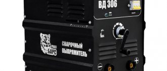
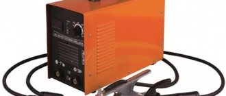
A welding converter is considered a type of operating current source, combining an electric motor, a generator and a rectifier in one housing. This installation is used during construction and installation work, when the electrical network sags and other welding machines operate unstably. Welding with a converter is carried out with a current of 500 amperes; you can weld thick workpieces and form a welding seam from 10 to 30 mm deep. The converter changes the voltage and type of current characteristics.
Principle of operation
The structure of all types of welding converters is typical:
- the current supplied to the asynchronous electric motor, after turning on the installation, is converted into mechanical current, which is supplied to the generator shaft;
- the generator produces the required frequency of current parameters, the method of electromagnetic induction is used in the work, an armature with windings is mounted on the shaft;
- The collector acts as a rectifier and supplies power to the output terminals.
A welding converter is essentially a combination of an electric motor operating from a 220 or 380 V network and a DC generator. The reliability of the converter is reduced by rotating components; energy losses in the process of converting electric current are high.
The equipment is valued for its stable current characteristics, regardless of surges in the voltage supplied to the motor. The regulator of performance characteristics is a rheostat; changing the number of turns of the independent winding changes the amperage. The output current is manually adjusted using an ammeter.
Models used
Currently, welding converters with a rated welding current of 315 A are used. The main purpose of these units is to supply direct current to one welding station. It can also be used to power manual arc welding, surfacing and cutting of metals with stick electrodes. Converters of this kind use generators of the GSO-300M and GSO-300 types. Their device is a four-pole self-excited DC commutator machine. The only difference between these two models is that they have different generator shaft speeds. This is regarding the 315 welding converter. 500 A is the second rated current, which is also used for operation. However, here it is already necessary to connect a more powerful converter, for example, model PD-502. The significant difference between this converter model and the GSO is that it has independent excitation. The point here is that to power the PD-502, three-phase alternating current is used, which first passes through an inductive-capacitive voltage converter. Along with the power supply function, it also acts as a stabilizer for this model of the unit.
However, it is important to understand that the main purpose of the welding converter is to convert variable electrical energy into constant electrical energy.
What is the difference between a welding converter and a generator?
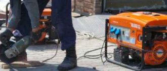
Generating installations are similar in the principle of generating operating current for welding. The generator runs on liquid fuel; the engine is petrol or diesel. The fuel operating principle is necessary for field conditions, when you have to cook away from power lines. Thermal energy is transformed into electrical energy without converting to mechanical energy.
The welding converter is equipped only with an electric motor connected to a single-phase or three-phase network. The installation is more complex than a generator; the motor and current generator are connected indirectly - by a shaft that transmits mechanical energy obtained from electrical energy.
Types of converters
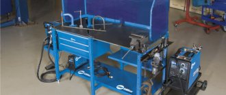
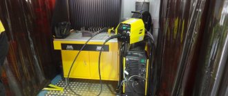
There are two main types of converters - stationary and mobile. If we talk about stationary types, then most often these are small welding booths or posts designed for working with small volumes of products. The welding converters installed here are not very powerful.
Mobile ones, in turn, are designed mainly for working with large volumes. They are often used to weld water pipes, oil pipelines, metal structures, etc.
It is important to add something else about the operating principle of this device. As stated earlier - it converts alternating current into direct current using the transition to mechanical energy. However, there are some devices that allow you to regulate the amount of DC output current. The adjustment process is carried out using devices such as ballast rheostats. The principle of operation is quite simple - the higher the resistance value set, the lower the output DC current and vice versa.
Device
You can examine the equipment design in detail using the example of a stationary welding converter PSO 500, which produces two operating modes with maximum current characteristics of 300 or 500 amperes. Between the electric motor rotor and the generator armature, located on the same shaft, there is a fan with an impeller, which provides targeted cooling of the contact zone, where there is a high friction force. The bearings are located in the converter housing; it must be grounded.
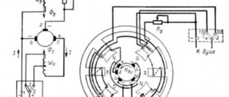
Device of welding converter PSO-500
The coil armature of the generator with 4 independent windings is connected to the collector, the rectifier plates are connected to the ends of the armature windings. When the coils rotate between the poles of the magnets, electromagnetic induction occurs and alternating current is induced. For winding, annealed copper or aluminum wire is used - metals with good electrical conductivity. To protect against external electromagnetic fields and vortex fields that arise during the operation of the converter, a “filter” is provided - an electrical capacitance (two capacitors that stabilize the voltage).
The control unit of the converter is modular. To start the welding converter, a packet is installed. An ammeter is located nearby, which is used to determine current parameters. The device is connected to a rheostat that regulates operating current indicators (measures the amperage in the circuit of an independent excitation winding).
After turning on the converter, it is important to check the direction of rotation of the generator windings. If necessary, the power terminals are swapped so that the rotor rotates counterclockwise. For the required operating current, the jumper is fixed in the “300 A” or “500 A” position (this is the maximum value of the generated electric current).
Transformer
Today, this is the simplest power source for a welding arc that produces only alternating current at the output.
Smooth control of the welding current is carried out by changing the gap in the choke coil or between the windings. Stepped - by switching the number of turns of the primary and secondary windings.
Transformers are very simple, which makes it possible to make it yourself. Currently, transformers are not relevant. This is due to the fact that direct current does not provide a stable arc, and its use when welding stainless steels is impossible.
Classification
Manufacturers produce converters of various modifications. When choosing generating installations, the type of welding and the intended place of work are taken into account. Classification of current sources for welding work is carried out according to several criteria:
- Number of welding stations. Single-station ones are designed for connection to one device, for the work of one welder. Multi-station welders can supply power to several welders and perform work simultaneously in several work areas.
- Structurally, they differ in size and type of execution. There are:
mobile welding installations, equipped with wheels or stand carts;
stationary, attached to the foundation or installed directly at the welder’s workplace.
- Depending on the number of bodies, welding installations can be single or double.
- By type of current indicators:
Classification of welding arc power sources
Welding arc power sources have many classifications, namely:
- according to supply voltage:
- single-phase (220V);
- three-phase (380V).
- according to external static characteristics:
- falling;
- hard;
- bayonet
- by the number of posts fed:
- single-post;
- multi-post.
- by type of current:
- variable;
- constant.
Safety precautions
Rules have been developed for working with generating electrical equipment. Before turning on, it is important to observe several points:
- Check the chassis grounding system, this is especially important for mobile installations; after transportation, you need to make sure that the grounding is reliable.
- The commutator brushes should be fine. To check, the rheostat steering wheel is moved to its extreme position, all the way (the direction of the steering wheel coincides with the movement of the windings - only counterclockwise).
- The next stage is to set the current parameters; control the position of the jumper.
- Connection to the network is carried out by a licensed electrician. It clamps the terminals on the electric motor in accordance with the safety rules of the PEU.
Operational requirements limit the current characteristics:
- permissible operating load 40 V;
- open circuit voltage is not higher than 85 V;
- when working in rooms with increased gas pollution, humidity, and dust, the permissible voltage is reduced to 12 V.
Special protective equipment is required: dielectric rubber mats, gloves. Welders need special clothing that protects the eyes, face, skin of the hands and feet from the effects of the welding electric arc and molten metal.
Flaws
However, the design features also determine the main disadvantages of welding converters, due to which they have been replaced by inverters, at least in the domestic sphere (welding work in small businesses, in the country, in the garage). First of all this:
- large dimensions and weight (it can reach half a ton or more);
- low efficiency;
- increased electrical hazard;
- noisy operation;
- need for service.
The principle of their operation - the transition of electrical energy into mechanical energy and vice versa - implies large energy costs for shaft rotation. This results in very high power consumption, making the device unprofitable for “home” use.
In addition, the presence of parts rotating at high speed reduces the reliability of the machine. The bottleneck of the cooking converter, like the electric motor itself, is the ball bearings on which the shaft is mounted.
They need periodic inspection and oil changes 1-2 times a year. It is also necessary to monitor the condition of the commutator and current collector brushes.
By increased electrical danger we mean the fact that before starting welding work, the converter must be grounded; according to the rules, its connection to the network must only be carried out by an electrician.
Advantages and disadvantages of inverter-type welding machines
An inverter welding machine, like any other equipment, has its advantages and disadvantages.
Diagram of an inverter type welding machine.
The main advantages of this equipment, which so skillfully replaced a conventional transformer, include:
- Due to a new approach to the production of inverter-type structures for welding metals, as well as new current control, most models weigh from 5 to 12 kilograms, in contrast to transformers, which weigh 18-35 kilograms.
- These devices have a fairly high efficiency rate. This is due to the fact that the device consumes a minimal amount of energy to heat all systems and mechanisms. For example, a welding transformer heats up quickly, which leads to overheating and equipment failure.
- In some transformer electrical circuits, as well as in inverters, welding can be carried out using electrodes, regardless of its type.
- The devices under consideration, due to their increased efficiency, consume half as much electricity as a simple transformer for welding.
- Many modern equipment have options in their structure, thanks to which the process of making mistakes by the master during technological work is minimized. Such options include anti-sticking and fast arc ignition.
- Some devices have a built-in programming function, thanks to which the master adjusts the operating mode during a specific type of welding process with precision and maximum efficiency.
- The high versatility of these designs is due to the regulation of all systems using current in a wide range. This makes it possible to use equipment that welds parts of different metals and performs the procedure using any technology.
The circuits of inverter welding machines also have disadvantages.
They are in the following aspects:
- Inverter welding equipment on the market is quite expensive, up to 50% more than the price of classic transformers for welding.
- The electrical circuit diagram of an inverter welding machine implies that most often a mechanism such as a transistor will break down. It is a rather vulnerable part, which entails repairs costing up to 60% of the cost of the entire equipment. From this we can conclude that repairs in themselves are an expensive pleasure.
- Since the basic electrical circuits of inverters for welding material are quite complex, experts do not recommend using them during bad weather or in the cold, so as not to damage the mechanisms and preserve the device for a long period. For welding work in the field or other open spaces, it is necessary to organize and build a special closed place with heating, where you can use this unit for welding.
Rectifier
Converts alternating current of industrial frequency into direct current, necessary for welding.
Rectifiers are single-phase and three-phase, stationary or mobile. Have the ability to change the current-voltage characteristic to hard or falling, as well as polarity when welding.
Smooth regulation of the welding current is carried out by the control unit, and stepwise regulation by switching the windings.
Their widespread use in production speaks of their versatility and productivity. High efficiency and the ability to be used when welding various metals make them one of the most popular power sources.
Technical components
The general structure of operation of such a device is simple, and includes a main current source, an optional rectifier element for the output current, and a common control unit.
A high-quality current source can be completely implemented on the basis of transformer technology or solely on the basis of an inverter system, where power transistors for welding inverters play an important role in the high-quality performance of the device.
For transformer installations, independent manual regulation of the operation of the device is allowed, but among the disadvantages are the rough adjustment mode and the low level of quality of the weld. Inverter installations, on the contrary, having the simplest welding inverter on a single transistor provide high quality weld formation, which is combined with power semiconductor elements.
Transistors for inverters
The main technical components that ensure high quality welding work are the presence of IGBT transistors, as well as universal high-speed diodes. In this case, a reasonable question arises: how to check the IGBT transistor of a welding inverter. We indicate the basic data of transistor components for welding the IGBT version
| Type | Characteristic |
| V | Ultra-low shutdown energy, operation up to 600 V, frequency up to 1200 kHz |
| NV | Low voltage saturated impact principle. Low shutdown energy. Voltage up to 650 Volts, frequency up to 50 kHz |
| N | Low effect of shutdown mode. Supply voltage – up to 1200 volts, frequency up to 35 kHz. |
| M | Low voltage saturation mode, mains voltage up to 1200 Volts, frequency parameter – up to 20 kHz |
| W | Low forward voltage drop mode, and minimal recovery effect mode. |
Features of operation of transistor units
The most common application scheme inside inverters is used using push-pull technology, a bridge operating principle, a half-bridge version of a working inverter, a half-bridge complex asymmetric version of an inverter device, or an oblique half-bridge. Despite the sufficient abundance of topologies, replacing the FGH40N60 transistor in a welding inverter according to general requirements is standard, which includes the following:
- High voltage mode. To effectively replace transistors in welding inverters, the total network voltage must be above 600 Volts.
- Large parameters of switching currents. The average value of the indicator should be at least tens of amperes, and the maximum parameters can show hundreds of amperes.
- High frequency switching mode. Depending on the dimensions of the transformer inside the device, you can increase the frequency of the device, as well as the inductance for the output filter model.
- For the mode of minimizing losses when turning the unit on and off, you can find out how to check the transistors of the welding inverter using a small value of energy supply to the on mode (Evkl), as well as to the shutdown mode (Eukl). In this case, all losses will be minimized.
- To minimize possible losses, we use a low value for the saturation voltage, or Uke us.
- The hard switching effect must be stable for transistors for Resanta welding inverters. In this case, inverter equipment only works with inductive load mode.
- Short circuit parameters. The device must have a resistance mode for this parameter; this information is extremely critical for bridge and half-bridge versions of inverter technology.
How to calculate power loss on IGBT?
We recommend using the diagram below for a detailed calculation of the correct choice of transistor systems.
| Options | Values |
| Total losses | Pd = Pcond + Pswitch |
| Conducted losses | Pcond = Uke us (rms) × Ik × D, where D is the duty cycle |
| Switching losses | Pswitch = Eswitch × f, where f is the switching frequency, Eswitch = (Eon + Eoff) - the total switching losses (given in the IGBT parameters) |
| Maximum power limited by chip overheating | Pd = (Tj – Tc)/Rth-jc, where Tc is the case temperature, Tj is the crystal temperature, Rth-jc is the “chip-to-case” thermal resistance (given in the IGBT parameters) |
All this data will help you correctly calculate the required type of transistor for an inverter welding machine. When choosing a transistor, we must take into account the parameter for the high threshold of the possible operating voltage of the device.
Operating principle and design of the welding inverter
To choose the right equipment for welding work, you need to know the design and operating principle of the welding inverter. If you have a good understanding of such issues, you can not only effectively use, but also repair inverter devices yourself.
Inverter welding machines made in Italy
There are many models of inverters offered on the modern market, which allows professionals to select equipment in accordance with their needs and financial capabilities. If you want to save money, you can make an inverter welding machine with your own hands.
How does an inverter welding machine work?
The operating principle of an inverter device is in many ways similar to the operation of a switching power supply. In both the inverter and the switching power supply, energy is transformed in a similar way.
The process of converting electrical energy in an inverter-type welding machine can be described as follows.
- Alternating current with a voltage of 220 Volts flowing in a regular electrical network is converted into direct current.
- The resulting direct current is again converted into alternating current using a special electrical circuit block of the inverter, but with a very high frequency.
- The voltage of high-frequency alternating current is reduced, which significantly increases its strength.
- The generated electric current, which has a high frequency, significant strength and low voltage, is converted into direct current, on which welding is performed.
Operating principle of a welding inverter
The main type of welding machines that were used previously were transformer devices, which increased the welding current by reducing the voltage value. The most serious disadvantages of such equipment, which is still actively used today, are low efficiency (since a large amount of consumed electrical energy is spent on heating the iron), large dimensions and weight.
The invention of inverters, in which the strength of the welding current is regulated according to a completely different principle, has made it possible to significantly reduce the size of welding machines, as well as reduce their weight. Effective regulation of the welding current in such machines becomes possible due to its high frequency. The higher the frequency of the current that the inverter generates, the smaller the dimensions of the equipment can be.
One of the main tasks that any inverter solves is increasing the frequency of standard electric current. This is possible due to the use of transistors that switch at a frequency of 60–80 Hz. However, as is known, only direct current can be supplied to transistors, while in a conventional electrical network it is alternating and has a frequency of 50 Hz. To convert alternating current into direct current, a rectifier assembled on the basis of a diode bridge is installed in inverter devices.
After the transistor block, in which high-frequency alternating current is generated, in welding inverters there is a transformer that lowers the voltage and, accordingly, increases the current. To regulate voltage and current at high frequencies, smaller transformers are required (at the same time, their power is not inferior to larger analogues).
Welding inverter without protective casing
Elements of the electrical circuit of inverter devices
The welding inverter device consists of the following basic elements:
- rectifier for alternating current coming from a regular electrical network;
- an inverter unit assembled on the basis of high-frequency transistors (such a unit is a generator of high-frequency pulses);
- a transformer that lowers the high-frequency voltage and increases the high-frequency current;
- high-frequency alternating current rectifier;
- working shunt;
- electronic unit responsible for controlling the inverter.
Whatever characteristics a particular model of inverter device has, the principle of its operation, based on the use of a high-frequency pulse converter, remains unchanged.
Example of an inverter circuit diagram (click to enlarge)
The rectifier and inverter units of the equipment become very hot during their operation, so they are installed on radiators that actively remove heat. In addition, to protect the rectifier unit from overheating, a special temperature sensor is used, which turns off its power supply when it reaches a temperature of 90 degrees.
The inverter unit, which is essentially a generator of high-frequency high-power pulses, is assembled on the basis of transistors connected like an “oblique bridge”. High-frequency electrical pulses generated in such a generator are sent to a transformer, which is necessary to lower their voltage.
The most common transformers used to equip welding inverters are devices with the following characteristics: primary winding - 100 turns of PEV grade wire (0.3 mm thick); 1st secondary winding – 15 turns of copper wire with a diameter of 1 mm; 2nd and 3rd secondary windings - 20 turns of copper wire with a diameter of 0.35 mm. All windings are carefully insulated from each other, and their exit points are protected and sealed.